Advertisement
Quick Links
RF Module | Installation
with Softswitch
Please read before installing
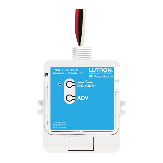
220 – 240 V~ 50 / 60 Hz 16 A
LMM-16R-DV-B
6 A Motor
Important Notes:
• For installation by a qualified electrician in accordance
with all local and national electrical codes.
• Note: Use copper conductors only.
• Check to see that the device type and rating is suitable
for the application.
• DO NOT install if product has any visible damage.
• If moisture or condensation is evident, allow the product
to dry completely before installation.
• Operate between 32 °F to 131 °F (0 °C to 55 °C).
• 0% to 90% humidity, non-condensing.
• For indoor use only.
Shock Hazard. May result in
serious injury or death.
WARNING
Turn off power at circuit breaker
before installing the unit.
Warranty:
For warranty information, please visit
www.lutron.com/TechnicalDocumentLibrary/Warranty.pdf
www.lutron.com/TechnicalDocumentLibrary/Intl_Warranty.pdf
Lutron and Softswitch are trademarks or registered trademarks
of Lutron Electronics Co., Inc. in the US and/or other countries.
©2013-2019 Lutron Electronics Co., Inc.
Lutron Electronics Co., Inc. | 7200 Suter Road
Coopersburg, PA 18036-1299, U.S.A.
Customer Assistance
RF Module Operation
041706-04
Rev. A
09/2019
For System Setup Guide and tools
visit www.lutron.com
Installation:
RF Module can be installed in a junction box or
marshalling box (optional) using the conduit nut
(provided) or with mounting screws (not provided).
Please consult local and national electric codes
for proper installation.
Live (Black)
Switched Hot (Red)
Neutral (White)
Wiring a Lever Operated Connector (shown)
1
3
When wiring lever operated connectors (3 supplied)
10 mm
2
please use 14 AWG to 12 AWG (2.5 mm
diameter solid or stranded copper wire.
220–240 V~ 50 / 60 Hz
Hereby, Lutron Electronics Co., Inc. declares that the radio equipment type
LMM-16R-DV-B are in compliance with Directive 2014/53/EU.
DoC can be obtained by writing to: Lutron Electronics Co., Inc. 7200 Suter Road,
Coopersburg, PA 18036 U.S.A.
RF Module Placement
RF Modules must be located within 30 ft (9 m) of an
RF signal repeater. RF Modules cannot be controlled
by the system until they are programmed using the
system programming software.
| +91.124.439.0130 Asia/Middle East | 1.844.LUTRON1 USA/Canada | +1.610.282.3800 Others | www.lutron.com/support
Load
Status
LED
To Load
(White)
Conduit Nut
21 mm Knockout Opening
2
to 4.0 mm
2
)
Complies with
ImDA Standards
DA103083
A copy of the
Toggle
Advanced
Operations
RF Module
Troubleshooting
Load does
• Ensure breaker to the RF Module
is on.
not respond
to Wireless
• Ensure the load has been
Transmitter(s).
properly wired to the RF Module.
• Ensure that the RF Module has
been activated in the system.
• Ensure that the Wireless
Transmitter battery is installed
correctly.
RF Module
• Improper programming.
does not
Program from the system
respond to
programming software.
a keypad,
• Out of RF Range.
wireless
Reposition to be within 30 ft (9 m)
controller or
of an RF signal repeater.
sensor.
• Already at current level. The RF
Module has already responded to
a command, or is already at the
requested setting.
• Wireless controller or sensor
batteries low or installed
incorrectly. Replace or install
batteries properly.
• RF interference.
Do not run RF Module wires
with other power wires or
communication wires (e.g.,
networking, audio, or video
signals).
Reset Factory Defaults
Note: In some instances it may be necessary to
reset the RF Module back to factory default settings.
A
Triple-tap the Advanced Operations ("ADV")
button, on the RF Module and hold until
the LED begins to flash slowly.
B
Within 3 seconds of flashing, release and
triple-tap the button again and the LED
will flash rapidly indicating that the unit
has been reset to factory defaults.
Note: Any associations or programming previously
set up with the unit will be lost and will need to be
re-programmed.
Advertisement

Subscribe to Our Youtube Channel
Related Manuals for Lutron Electronics LMM-16R-DV-B


Summary of Contents for Lutron Electronics LMM-16R-DV-B
- Page 1 LMM-16R-DV-B are in compliance with Directive 2014/53/EU. A copy of the button, on the RF Module and hold until DoC can be obtained by writing to: Lutron Electronics Co., Inc. 7200 Suter Road, the LED begins to flash slowly. Coopersburg, PA 18036 U.S.A.
- Page 2 Electronics Co., Inc. 7200 Suter Road, Coopersburg, PA 18036 USA。 的“ADV” 按钮)并按住,直至LED开 质量保证: 始缓慢闪烁。 关于质保的信息,请访问: www.lutron.com/TechnicalDocumentLibrary/Warranty.pdf 在开始闪烁的3秒内,松开按钮并再次轻 www.lutron.com/TechnicalDocumentLibrary/Intl_Warranty.pdf RF 模块布置 按按钮三次,这时LED将会快速闪烁,以 示装置已被重新设置为出厂默认设置。 Lutron和Softswitch是Lutron Electronics Co., Inc.在美国和/或 RF模块必须安装在RF信号中继转发器9 m的范围以内。 其他国家的商标或注册商标。 ©2013-2019 Lutron Electronics Co., Inc. 在使用系统程序设计软件编程之前,RF模块不受系统控制。 注:任何曾与该装置相关的连接或程序设计均 将丢失,您需要重新进行程序设计。 Lutron Electronics Co., Inc. | 7200 Suter Road Coopersburg, PA 18036-1299, U.S.A.
Need help?
Do you have a question about the LMM-16R-DV-B and is the answer not in the manual?
Questions and answers