Table of Contents
Advertisement
Available languages
Available languages
Quick Links
Please Read
D i m m i n g a n d S w i t c h i n g P a n e l s
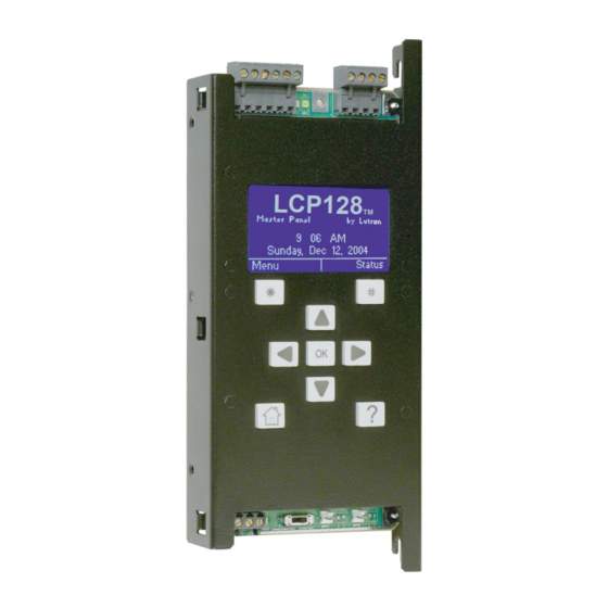
LCP Panel shown
Overview
Use this guide to successfully install a dimming and switching panel. This guide describes panel installation,
wiring, and load activation.
®
LCP128
GRAFIK Systems
Contents
Panel Model Number Guide
LCP128 (LCP) Panels
GRAFIK Systems (LP) Panels
GRAFIK Systems (CCP) Panels
GRAFIK Systems (CCP/LCP) Panels
Panel Dimensions
Mini Panel
Standard Panel
Panel Mounting
Wiring/Ratings
System Wiring Overview
Feed and Load Wiring Overview
Temporary Lighting
Ratings
Feed Through Panel: Feed and Load Wiring
Panel with Main Lugs: Feed Wiring
Panel with Main Lugs: Load Wiring
Activate Loads in Bypass
Complete Installation
Remove Bypass Jumpers
Warranty
Contact Information
Installation Guide
(LCP) and
TM
(LP and CCP)
TM
®
2
3
4
5
6
7
8
9
10
10
11
12
14
15
16
17
17
19
20
Advertisement
Chapters
Table of Contents

Related Manuals for Lutron Electronics LCP128


Summary of Contents for Lutron Electronics LCP128
- Page 1 D i m m i n g a n d S w i t c h i n g P a n e l s Installation Guide LCP128 (LCP) and GRAFIK Systems (LP and CCP) Contents Panel Model Number Guide LCP128 (LCP) Panels GRAFIK Systems (LP) Panels GRAFIK Systems (CCP) Panels GRAFIK Systems (CCP/LCP) Panels Panel Dimensions Mini Panel Standard Panel Panel Mounting...
- Page 2 Panel Model Number Guide LCP128 (LCP) (120 V only) See page 5 for 230 / 220–240 V Example L C P - 2 X 2 D 1 A 4 T - 1 2 0 4 M L - 2 0...
- Page 3 Panel Model Number Guide (continued) GRAFIK Systems (LP) (all voltages) Example L P 7 / 2 8 - 1 2 0 4 M L - 2 0 - C G P _ _ _ _ Custom Panel Prefix Feed Suffix Voltage Branch Circuit (contact...
- Page 4 Panel Model Number Guide (continued) GRAFIK Systems (CCP) (120 V only) Example C C P - 2 X 2 L 1 A 4 T - 1 2 0 4 M L - 2 0 - C G P _ _ _ Prefix Modules: Feed...
- Page 5 See table below for limits 2L = 2Link circuit selector on numbers of modules per panel. LCP = LCP128 X = Four-Circuit Switching (Relay) (XP) Custom Panel Suffix (optional) L = Four-Circuit Dimming (4U) Indicates panel with special options...
-
Page 6: Panel Dimensions Mini Panel
Panel Dimensions Mini Panel Dimensions are in inches (mm). 14.375 (365) Top View 15.875 (403) 4.21 (107) 8.00 (56) (203) 0.15 1.34 (34) 21.50 (546) 24.00 24.50 (610) (622) Cover 10.75 Left Side Right Side 2.21 (273) (56) 15.13 (384) Front View 4.09 (104) -
Page 7: Standard Panel
Panel Dimensions (continued) Standard Panel Dimensions are in inches (mm). 14.375 (365) Top View 15.875 (403) 4.21 2.43 8.00 (107) (62) (203) 0.15 2.69 (68) 41.75 (1060) 59.50 59.00 (1511) (1499) Cover 11.00 2.43 Left Side Right Side (279) (62) 15.125 (394) Front View... -
Page 8: Panel Mounting
Do not • Mount to wall stud by screwing through slots in obstruct corners of panel. vents! • Mount panel between flush and 1/8 in (3 mm) Air flow below finished wall surface. Recommended Mounting Heights* (for LCP128 systems) PELV Mini 45 in (1143 mm) (Class 2: USA) Standard 25 in (635 mm) Wiring * Measure from floor to bottom of panel;... -
Page 9: System Wiring Overview
System Wiring Overview A. LCP128 panel: Contact closure input Contact closure input Refer to the LCP128 Setup and (CCI) 1 (CCI) 2 Operation Manual for detailed wiring information. 1 2 3 4 D 5 1 2 3 4 Controller Terminals B. -
Page 10: Feed And Load Wiring Overview
Wiring (continued) Feed and Load Wiring Overview Feed Wiring (Mains Voltage Wiring) • Preferred feed wiring entry for panels with main lugs/isolation switch is from the bottom left of the panel. • Preferred feed wiring entry for feed-through panels is from the top or bottom left of the panel, wired directly to module terminal blocks. • Run wiring so that line (mains) voltage wiring will be at least 6 ft (1.8 m) from sound or electronic equipment and its wiring. • Refer to Feed Wiring pages for more information. Load Circuit Wiring • Connect load wiring to the appropriate terminal block set for each module. • For 230 V and 240 V panels, “Hot” is referred to as “Live”. Therefore, terminals will be labeled DL and L. -
Page 11: Ratings
Ratings LP/LCP/CCP Panels Feed-Through Panels (all voltages) Number Feed Max. Type Feed Modules 120 V : 20 A 1Ø 2W 230 V : 13 A or 16 A 220 to 240 V : 16 A 14 to 10 AWG (2.5 to 4.0 mm Panels with Breaker Panels with Main Lugs (120 V... - Page 12 Feed-Through Panel: Feed and Load Wiring (all voltages) General Notes • Typical dimming/switching legs shown. • Do not remove bypass jumpers until after load wiring has been verified. Wire sizes for power feed, to each input • Power feed: 14 to 10 AWG (2.5 to 4.0 mm • Neutral feed: 14 to 10 AWG (2.5 to 4.0 mm Wire sizes for load wiring, from each output See terminal • Dimmed hot (live): 14 to 10 AWG (2.5 to 4.0 mm block modules • Load neutral: 14 to 10 AWG (2.5 to 4.0 mm for specific wiring details.
- Page 13 Feed-Through Panel: Feed and Load Wiring (continued) 4-Circuit Motor Module (4M) Raise Lower Circuit breaker Connecting an NGRX-FDBI to a Panel Hot/Live Bypass jumper Load Feed Feed Dimmed Hot/Live Neutral Neutral Hot/ hot/live Live Lutron ® FDBI Neutral Lutron ® Feed Eco-10 ®...
-
Page 14: Panel With Main Lugs: Feed Wiring
Panel with Main Lugs: Feed Wiring Dimming and Switching Panels (120 V only) Notes • See page 15 for load wiring details. • On dimming panels only, the input breaker of Circuit 1 supplies current to Load Circuit Breakers 1 and to the Control Wiring (2 A draw max.). -
Page 15: Panel With Main Lugs: Load Wiring
Panel with Main Lugs: Load Wiring Typical Dimming/Switching Leg Shown Notice: Do not remove bypass jumpers until after load wiring has been verified. 4-Circuit Dimming Module (4U) 4-Circuit Adaptive Dimming Module (4A) 4-Circuit ELV Dimming Module (4E: 230 V and 220 to 240 V only) 4-Circuit Motor Module (4M) 4-Circuit Fan Speed Control Module (4FSQ) -
Page 16: Activate Loads In Bypass
LCP-8D-1204ML-20 shown the circuit breaker’s limit and less than or equal to 16 A. ‘Power OK’ LED at the bottom of LCP128 Controller E. Repeat step D for each circuit with completed load wiring. ‘Power OK’ LED at the top of LP/CCP Circuit Selector... -
Page 17: Complete Installation
For Onsite Factory Commissioning, call Lutron Technical Support and select Startup to schedule a field service visit. Allow for 10 working days between day of call and scheduled visit. If you purchased Telephone Startup (LCP128 only), stop here and complete the Control Location, Panel, and Control Station Tables that are located in the back of the Setup and Operation Manual. - Page 18 Notes Installation Guide for Dimming and Switching Panels ®...
-
Page 19: Warranty
Tridonic is a registered trademark of Zumtobel Aktiengesellschaft. Lutron, the sunburst logo, GRAFIK Eye, GRAFIK 6000, Eco-10, and Hi-lume are reg is tered trademarks, and LCP128, GRAFIK Systems, GRAFIK 5000, GRAFIK 7000, and 2Link are trademarks of Lutron Electronics Co., Inc. - Page 20 Contact Information Internet: www.lutron.com E-mail: product@lutron.com WORLD HEADQUARTERS Lutron Electronics Co., Inc. 7200 Suter Road, Coopersburg, PA 18036-1299 TEL +1.610.282.3800 FAX +1.610.282.1243 Toll-Free 1.888.LUTRON1 Technical Support 1.800.523.9466 North and South America Technical Hotlines USA, Canada, Caribbean: 1.800.523.9466 Mexico: +1.888.235.2910 Central/South America: +1.610.282.6701...
-
Page 21: Table Of Contents
Guía de Instalación LCP128 (LCP) y GRAFIK Systems (LP y CCP) Contenido Guía de Números de Modelo del Panel Paneles LCP128 (LCP) Paneles GRAFIK Systems (LP) Paneles GRAFIK Systems (CCP) Paneles GRAFIK Systems (CCP/LCP) Dimensiones del Panel Mini Panel Panel Estándar... - Page 22 Guía de Números de Modelo del Panel LCP128 (LCP) (120 V solamente) Vea la página 5 para 230 / 220 - 240 V Ejemplo L C P - 2 X 2 D 1 A 4 T - 1 2 0 4 M L - 2 0 Prefijo Módulos:...
- Page 23 Guía de Números de Modelo de Panel (continuación) GRAFIK Systems (LP) (todos los voltajes) Ejemplo L P 7 / 2 8 - 1 2 0 4 M L - 2 0 - C G P _ _ _ Tipo de Sufijo de Panel Personalizado Alimentación Prefijo...
- Page 24 Guía de Números de Modelo de Panel (continuación) GRAFIK Systems (CCP) (120 V solamente) Ejemplo C C P - 2 X 2 L 1 A 4 T - 1 2 0 4 M L - 2 0 - C G P _ _ _ Alimentación Prefijo Módulos:...
- Page 25 2L = selector de circuitos 2Link módulos por panel. LCP = LCP128 X = Módulo Interruptor de Cuatro Circuitos Relé) (XP) Sufijo del Panel Personalizado (opcional) L = Atenuación de cuatro circuitos (4U) Indica panel con opciones especiales A = Módulo de Atenuación Adoptivo de cuatro...
-
Page 26: Dimensiones Del Panel
Dimensiones del Panel Mini Panel Todas las dimensiones están en mm. Vista Superior Cubierta Lado Izquierdo Lado Derecho Vista Frontal Vista Inferior 6 Guía de Instalación para Paneles de Atenuación y de Interruptores ®... -
Page 27: Panel Estándar
Dimensiones del Panel (continuación) Panel Estándar Todas las dimensiones están en mm. Vista Superior 1 060 1 511 1 499 Cubierta Lado Izquierdo Lado Derecho Vista Frontal Vista Inferior Guía de Instalación para Paneles de Atenuación y de Interruptores 7 ®... -
Page 28: Montaje En Panel
• Monte el panel entre el ras y 3 mm debajo del Flujo de Aire acabado de la superficie de la pared. Alturas Recomendadas de Montaje* (para sistemas LCP128 Cableado PELV Mini 1 143 mm (Clase 2: E.U.A.) Estándar 635 mm... - Page 29 Contactos secos de Contactos secos de entrada (CCI) 1 entrada (CCI) 2 Operación de LCP128 por información detallada del cableado. 1 2 3 4 D 5 1 2 3 4 Bornes del Controlador B. Panel LP o CCP como parte de un sistema de iluminación GRAFIK Eye...
-
Page 30: Descripción General Del Cableado De Alimentación Y De Carga
Cableado (continuación) Descripción General del Cableado de Alimentación y de Carga Cableado de alimentación (cableado de voltaje de la red) • La entrada del cableado de alimentación preferida para los paneles con zapatas principales/interruptor de aislación es desde el extremo izquierdo del panel. • La entrada del cableado de alimentación para los paneles sin interruptores de circuitos es desde el extremo superior o inferior izquierdo del panel, cableado directamente hasta los bloques de terminales del módulo. • Tienda los cables de modo que el cableado de la línea de voltaje (red eléctrica) quede al menos a 1,83 m de equipos de sonido o electrónicos y su cableado. -
Page 31: Valores Nominales
Valores Nominales LP/LCP/CCP Paneles Paneles de Alimentación (todos los voltajes) Número Alimentación Alimentación Tipo máxima Módulos 120 V : 20 A 1Ø 2W 230 V : 13 A o 16 A 220 - 240 V : 16 A 2,5 a 4,0 mm (14 a 10 AWG) Paneles con Cortacircuitos Paneles con Zapatas Principales... - Page 32 Panel sin interruptores de circuitos: Cableado de alimentación y de carga (todos los voltajes) Notas Generales • Se muestran ramales típicos de atenuación/interruptores • No quite los puentes de desviación hasta que el cableado de carga haya sido verificado. Tamaños de cable para alimentación de potencia, para cada entrada • Alimentación de potencia: 2,5 a 4,0 mm (14 a 10 AWG) Vea los módulos • Alimentación del Neutro: 2,5 a 4,0 mm (14 a 10 AWG) de los bloques...
- Page 33 Panel sin interruptores de circuitos: Cableado de Alimentación y de Carga (continuación) Módulo de Motor de 4 Circuitos (4M) Aumentar Disminuir Cortacircuitos Conexión de un NGRX-FDBI a un Panel Vivo Puente de derivación Carga Alimentación Alimentación Vivo/hot Vivo Neutro Neutro Atenuado Vivo Lutron...
-
Page 34: Cableado De La Alimentación Y De La Carga
Paneles con Zapatas Principales: Cableado de alimentación Paneles de Atenuación y de Interruptores (120 V solamente) Notas • Vea la página 15 para detalles del cableado de la carga. • En paneles de atenuación solamente, el Cortacircuitos cortacircuitos de entrada del Circuito 1 suministra corriente al Circuito de Carga 1 y al Cableado de Control (2 A máximo). - Page 35 Panel con Zapatas Principales: Cableado de Carga Se Muestra un Ramal de Atenuación/Interruptores Aviso: No quite los puentes de desviación hasta que Típico el cableado de carga haya sido verificado. Módulo de Atenuación de 4-Circuitos (4U) Módulo de Atenuación Adoptivo de 4 circuitos (4A) Módulo de Motor de 4 Módulo de Atenuación BVE de 4-Circuitos Circuitos (4M)
-
Page 36: Active Cargas En Los Puentes De Desviación
Se muestra LCP-8D-1204ML-20 busque un cableado incorrecto en el vínculo de bajo voltaje. LED ‘Power OK’ al final del Controlador LCP128 D. Encienda el cortacircuito siguiente. La carga deberá energizarse, el cortacircuito LED ‘Power OK’ no deberá dispararse y la corriente total de en la parte superior del Selector de la carga deberá... -
Page 37: Instalación Completa
Deje pasar 10 días hábiles entre el día de su llamada y la visita programada. Si usted compró Inicio Telefónico (solamente LCP128 ), deténgase aquí y complete las Tablas de Ubicación del Control, Panel, y Estación de Control ubicadas en la parte posterior del Manual de Configuración y Operación. - Page 38 Notas: 18 Guía de Instalación para Paneles de Atenuación y de Interruptores ® ®...
-
Page 39: Garantía
Lutron, el logo sunburst, GRAFIK Eye, GRAFIK 6000, Eco-10, y Hi-lume son marcas registradas de Lutron Electronics Co., Inc.; LCP128, GRAFIK Systems, GRAFIK 5000, GRAFIK 7000, y 2Link son marcas comerciales de Lutron Electronics Co., Inc. © 2010 Lutron Electronics Co., Inc. -
Page 40: Información De Contacto
Información de contacto: Internet: www.lutron.com E-mail: product@lutron.com SEDE CENTRAL MUNDIAL E.U.A. Lutron Electronics Co., Inc. 7200 Suter Road, Coopersburg, PA 18036-1299 TEL: +1.610.282.3800 FAX: +1.610.282.1243 Llamada Gratuita 1.888.LUTRON1 Soporte Técnico 1.800.523.9466 Líneas de Asistencia Técnica Para América del Norte y América del Sur E.U.A., Canadá, Caribe: 1.800.523.9466... - Page 41 D i m m e r - u n d S c h a l t s c h r ä n k e Installationsanleitung LCP128 (LCP) und GRAFIK Systems (LP und CCP) Inhalt Übersicht zu Schrankmodellnummern LCP128-Schränke (LCP) GRAFIK Systems-Schränke (LP) GRAFIK Systems-Schränke (CCP) GRAFIK Systems-Schränke (CCP/LCP) Schrankabmessungen Mini-Schrank Standardschrank Schrankmontage Verkabelung/Nennwerte Übersicht über die Systemverkabelung...
- Page 42 Übersicht über Schrankmodellnummern LCP128 (LCP) (nur 120 V Siehe Seite 5 für 230/220-240 V Beispiel L C P - 2 X 2 D 1 A 4 T - 1 2 0 4 M L - 2 0 Präfix Module: Speisespannung Nennwert für...
- Page 43 Übersicht über Schrankmodellnummern (Fortsetzung) GRAFIK Systems (LP) (alle Spannungen) Beispiel L P 7 / 2 8 - 1 2 0 4 M L - 2 0 - C G P _ _ _ _ Suffix für spezifisch Präfix Speises- maßgeschneiderte pannung Nennwert für Schränke (fragen Sie Lutron...
- Page 44 Übersicht über Schrankmodellnummern (Fortsetzung) GRAFIK Systems (CCP) (nur 120 V Beispiel C C P - 2 X 2 L 1 A 4 T - 1 2 0 4 M L - 2 0 - C G P _ _ _ Präfix Module: Speises-...
- Page 45 Die Anzahl kommt vor jeden Modulcode. 2L = 2Link -Schaltschrank-Kontroller Codes für Module, die im Schrank nicht verwendet LCP = LCP128 werden, werden weggelassen. Siehe die Tabelle unten Suffix für spezifisch maßgeschneiderte Schränke für maximale Modulanzahlen pro Schrank. (optional)
-
Page 46: Schrankabmessungen
Schrankabmessungen Mini-Schrank Abmessungen sind in mm. Draufsicht Abdeckung Linke Seite Rechte Seite Vorderansicht Ansicht von unten Installationsanleitung für Dimmer- und Schaltschränke ®... -
Page 47: Standardschrank
Schrankabmessungen (Fortsetzung) Standardschrank Abmessungen sind in mm. Draufsicht 1 060 1 511 1 499 Abdeckung Linke Seite Rechte Seite Vorderansicht Ansicht von unten Installationsanleitung für Dimmer- und Schaltschränke 7 ®... -
Page 48: Schrankmontage
Lüftungsöffnungen nicht blockieren! durch die Schlitze in den Ecken des Schranks hineinschrauben. • Den Schrank zwischen der Wandoberfläche und Luftzirkulation 3 mm unterhalb der fertigen Wandoberfläche montieren. Empfohlene Montagehöhen* (für LCP128 -Systeme) PELV- Mini 1 143 mm Verkabelung Standard 635 mm (Klasse 2: USA) * Vom Boden zur Schrankunterseite messen. -
Page 49: Übersicht Über Die Systemverkabelung
-Schrank: Detaillierte Kontakten (CCI) 1 Kontakten (CCI) 2 Informationen zur Verkabelung finden Sie in der Einstellungs- und Betriebsanleitung für LCP128. 1 2 3 4 D 5 1 2 3 4 Kontrollerklemmen B. LP- oder CCP-Schrank als Teil eines Beleuchtungssystems GRAFIK Eye... -
Page 50: Übersicht Über Die Einspeisungs- Und Lastverkabelung
Verkabelung (Fortsetzung) Übersicht über die Einspeisungs- und Lastverkabelung Einspeisung (Zuleitung) • Führen Sie die Einspeisungsverkabelung für Schränke mit Netzeinspeisung/Trennschalter nach Möglichkeit von links unten in den Schrank ein. • Führen Sie die Einspeisungsverkabelung für durchverdrahtete Schränke auf der linken Seite von oben oder unten in den Schrank ein und schließen Sie sie unmittelbar an die Klemmenblöcke der Module an. • Die Kabel sind so zu führen, dass Netzspannungen mindestens 1,83 m von Audio- oder elektronischen Anlagen und deren Verdrahtung entfernt liegen. • Weitere Informationen finden Sie auf den Seiten zur Einspeisungsverkabelung. -
Page 51: Nennkapazitäten
Nennkapazitäten LP/LCP/CCP-Schränke Durchverdrahtete Schränke (alle Spannungen) Anzahl Einspeisung Max. Eingangsstrom Module 120 V : 20 A 1Ø 2W 230 V : 13 A oder 16 A 220 - 240 V : 16 A 2,5 bis 4,0 mm (AWG 14 bis 10) Schränke mit Sicherungsautomat Schränke mit Hauptklemmen (nur 120 V... - Page 52 Durchverdrahteter Schrank: Einspeisungs- und Lastverkabelung (alle Spannungen) Allgemeine Hinweise • Abbildung typischer Dimmer-/Schalterabgänge. • Die Bypass-Verbinder nicht entfernen, bis die Lastverkabelung überprüft worden ist. Leitungsgrößen für die Stromversorgung, zu jedem Eingang • Stromversorgung: 2,5 bis 4.0 mm (AWG 14 bis 10) • Nullleiter der Speiseleitung: 2,5 bis 4.0 mm (AWG 14 bis 10) Siehe Leitungsgrößen für die Lastverkabelung, von jedem Ausgang Klemmenblockmodule • Gedimmte Phase: 2,5 bis 4.0 mm (AWG 14 bis 10)
-
Page 53: Durchverdrahteter Schrank: Einspeisungs- Und Lastverkabelung
Durchverdrahteter Schrank: Einspeisungs- und Lastverkabelung (Fortsetzung) 4-Kreis-Motormodul (4M) Heller Dunkler Sicherungs- automat Anschluss eines NGRX-FDBI an einen Schrank Phase Bypass-Verbinder Last Einspeisung Gedimmte Einspeisung Phase Phase Nullleiter Nullleiter Phase Nullleiter Lutron Einspeisung ® Eco-10 oder Lutron ® ® Hi-lume FDBI ®... -
Page 54: Schrank Mit Hauptklemmen: Einspeisungsverkabelung
Schrank mit Hauptklemmen: Einspeisungsverkabelung Dimmer- und Schaltschränke (nur 120 V Hinweise • Siehe Seite 15 für Einzelheiten zur Lastverkabelung. Sicherungs- • Nur an Dimmerschränken versorgt der automaten Eingangs-Sicherungsautomat von Kreis 1 Lastkreis 1 und die Steuerleitungen mit Strom (max. 2 A). Schränke mit Erdungsschiene Schaltmodulen haben einen eigenen Sicherungsautomaten für den Steuerkreis. -
Page 55: Schrank Mit Hauptklemmen: Lastverkabelung
Schrank mit Hauptklemmen: Lastverkabelung Abbildung eines typischen Dimmer/Schalterabgangs Notiz: Die Bypass-Verbinder nicht entfernen, bis die Lastverkabelung überprüft worden ist. 4-Kreis-Dimmermodul (4U) Adaptives 4-Kreis-Dimmermodul (4A) 4-Kreis-Motormodul (4M) 4-Kreis-ELV-Dimmermodul – (4E: 230 V und 220 240 V 4-Kreis-Modul zur Gebläse-Geschwindigkeitsregelung (4FSQ) Heller Bypass-Verbinder Gedimmte Phase Jalousie... -
Page 56: Einschalten Der Lasten In Bypass-Betriebsart
(Sicherungsautomat 1) AUS und überprüfen LCP-8D-1204ML-20 abgebildet Sie, ob der Niederspannungs-Link falsch verdrahtet ist. LED “Power OK” (Netz OK) unten am LCP128-Kontroller D. Schalten Sie den nächsten Sicherungsautomaten EIN. LED “Power OK” (Netz OK) Die Last wird eingeschaltet, die Sicherung darf oben am LP/CCP-Schaltschrank- nicht auslösen, und der gesamte Laststrom... -
Page 57: Installationsabschluss
“Inbetriebnahme”, um den Besuch eines Außendienst-Technikers zu beantragen. Lassen Sie 10 Arbeitstage bis zum Tag des Besuchs. Wenn Sie Inbetriebnahme per Telefon gewählt haben (nur LCP128 ), füllen Sie jetzt die Tabellen für Steuerstellen-Standort, Schrank und Steuereinheit aus, die sich hinten in der Einstellungs- und Betriebsanleitung befinden. - Page 58 Notizen 18 Installationsanleitung für Schaltschränke ®...
-
Page 59: Garantie
Tridonic ist eine eingetragene Warenzeichen von Zumtobel Aktiengesellschaft. Lutron, das Sunburst-Logo, GRAFIK Eye, GRAFIK 6000, Eco-10, und Hi-lume sind eingetragene Warenzeichen von Lutron Electronics Co., Inc.; LCP128, GRAFIK Systems, GRAFIK 5000, GRAFIK 7000, und 2Link sind Warenzeichen von Lutron Electronics Co., Inc. -
Page 60: Kontaktinformationen
Kontaktinformationen Internet: www.lutron.com E-Mail: product@lutron.com WELTWEITE ZENTRALE Lutron Electronics Co., Inc. 7200 Suter Road, Coopersburg, PA 18036-1299 TEL. +1.610.282.3800 FAX +1.610.282.1243 Gebührenfrei 1.888.LUTRON1 Technische Unterstützung 1.800.523.9466 Technische Hotlines für Nord- und Südamerika USA, Kanada, Karibik: 1.800.523.9466 Mexiko: +1.888.235.2910 Mittel-/Südamerika: +1.610.282.6701 EUROPAZENTRALE Großbritannien... - Page 61 Guide d’installation LCP128 (LCP) et GRAFIK Systems (LP et CCP) Contenu Guide des numéros des modèles d’armoire Armoires LCP128 (LCP) Armoires GRAFIK Systems (LP) Armoires GRAFIK Systems (CCP) Armoires GRAFIK Systems (CCP/LCP) Dimensions de l’armoire Armoire mini Armoire standard Montage de l’armoire Câblage/caractéristiques nominales...
- Page 62 Guide des numéros de modèles d’armoire LCP128 (LCP) (120 V uniquement) Voir en page 5 pour 230 / 220 - 240 V Exemple L C P - 2 X 2 D 1 A 4 T - 1 2 0 4 M L - 2 0 Préfixe...
- Page 63 Guide des numéros de modèles d’armoire (suite) GRAFIK Systems (LP) (toutes les tensions) Exemple L P 7 / 2 8 - 1 2 0 4 M L - 2 0 - C G P _ _ _ _ Suffixe de l’armoire Préfixe Tension Caractéristique...
- Page 64 Guide des numéros de modèles d’armoire (suite) GRAFIK Systems (CCP) (120 V uniquement) Exemple C C P - 2 X 2 L 1 A 4 T - 1 2 0 4 M L - 2 0 - C G P _ _ _ Préfixe Modules : Tension...
- Page 65 Ignorer les codes pour les modules non 2L = sélecteur de circuit 2Link utilisés dans l’armoire. Se reporter au tableau suivant LCP = LCP128 pour connaître les limites sur les numéros des modules par armoire. Suffixe de l’armoire personnalisée (option) Signale une armoire dotée d’options spéciales...
-
Page 66: Dimensions De L'armoire
Dimensions de l’armoire Armoire mini Les dimensions sont exprimées en mm. Vue de dessus Couvercle Côté gauche Côté droit Vue de face Vue de dessous 6 Guide d’installation des armoires de gradation et de commutation ®... -
Page 67: Armoire Standard
Dimensions de l’armoire (suite) Armoire standard Les dimensions sont exprimées en mm. Vue de dessus 1 060 1 511 1 499 Couvercle Côté gauche Côté droit Vue de face Vue de dessous Guide d’installation des armoires de gradation et de commutation 7 ®... - Page 68 • Pour le montage affleurant, placer l’armoire entre la position d’affleurement et 3 mm en dessous Circulation de l’air de la surface du mur. Hauteurs de montage recommandées* (pour les systèmes LCP128 Câblage TBTP Armoire mini 1 143 mm (Classe 2 : É.-U.) Armoire standard 635 mm * Mesurer entre le sol et le bas de l’armoire pour avoir une vue optimale du...
-
Page 69: Vue Générale Du Câblage Du Système
Entrée avec contacts Entrée avec contacts secs se reporter au manuel de secs (CCI) 1 (CCI) 2 configuration et d’utilisation LCP128 pour en savoir plus sur le câblage. 1 2 3 4 D 5 1 2 3 4 Bornes du contrôleur B. -
Page 70: Vue Générale Du Câblage D'alimentation Et Des Charges
Câblage (suite) Vue générale du câblage de l’alimentation et des charges Câblage d’alimentation (câblage de la tension secteur) • L’entrée du câblage d’alimentation recommandée pour les armoires avec bornes de raccordement/ sectionneur se fait par la partie inférieure gauche de l’armoire. • L’entrée du câblage d’alimentation recommandée pour les armoires livrées sans disjoncteur se fait par la partie supérieure ou la partie inférieure gauche de l’armoire, directement câblée aux bornes du module. • Effectuer le câblage de telle sorte que le câblage d’alimentation soit distant d’au moins 1,83 m de tout appareil électronique ou sonore et de son câblage. -
Page 71: Caractéristiques Nominales
Caractéristiques nominales Armoires LP/LCP/CCP Armoires sans protection (toutes les tensions) Nombre Alimentation Alimentation Type maximum modules 120 V : 20 A 1Ø 2W 230 V : 13 A ou 16 A 220 - 240 V : 16 A 2,5 à 4,0 mm (14 à... - Page 72 Armoire sans protection : câblage de l’alimentation et des charges (toutes les tensions) Remarques générales • Bornes types pour gradation/commutation représentées. • Ne pas retirer les cavaliers de dérivation tant que le câblage des charges n’a pas été vérifié. Dimensions des câbles d’alimentation, vers chaque entrée • Câble d’alimentation : 2,5 à 4,0 mm (14 à 10 AWG) • Câble du neutre : 2,5 à 4,0 mm (14 à 10 AWG) Dimensions des câbles pour le câblage de charge, depuis chaque sortie Consulter les • Phase soumise à gradation (live) : 2,5 à 4,0 mm...
- Page 73 Armoire sans protection : câblage de l’alimentation et des charges (suite) Module de moteur à 4 circuits (4M) Augmenter Diminuer Disjoncteur Sous de circuit tension/ Raccordement d’une armoire NGRX-FDBI Actif Cavalier de dérivation Sous tension/ Charge actif soumis à Alimentation Alimentation gradation Sous tension/...
-
Page 74: Armoire Avec Bornes De Raccordement : Câblage De L'alimentation
Armoire avec bornes de raccordement : câblage de l’alimentation Armoires de gradation et de commutation (120 V uniquement) Remarques • Consulter la page 15 pour en savoir plus sur le câblage des charges. • Uniquement sur les armoires de gradation, Disjoncteurs le disjoncteur d’entrée du circuit 1 alimente le circuit de charge 1 et le câblage de... -
Page 75: Armoire Avec Bornes De Raccordement : Câblage Des Charges
Armoire avec bornes de raccordement : câblage des charges Borne type pour gradation/commutation Avis : Ne pas retirer les cavaliers de dérivation tant représentée que le câblage des charges n’a pas été vérifié. Module de gradation à 4 circuits (4U) Module de gradation adaptable à... -
Page 76: Activer Les Charges En Dérivation
(disjoncteur 1) sur OFF et rechercher un éventuel mauvais LED d’alimentation OK (‘Power OK’ câblage sur la liaison basse tension. LED) au bas du contrôleur LCP128 D. Mettre le disjoncteur suivant sur ON. LED d’alimentation OK ‘‚Power OK’ L a charge doit être activée, le disjoncteur LED) au-dessus du sélecteur de circuit... -
Page 77: Fin De L'installation
Pour obtenir une mise en service sur site par l’usine, appeler le support technique de Lutron et sélectionner Démarrage pour programmer une visite. Prévoir 10 jours ouvrables entre l’appel et la visite. Si l’option télé-démarrage a été choisie (LCP128 uniquement), il convient de s’interrompre à ce stade pour compléter les tableaux d’emplacement des commandes, de l’armoire et des unités de commande qui... - Page 78 Remarques 18 Guide d’installation des armoires de gradation et de commutation ® ®...
-
Page 79: Garantie
Tridonic est une marque déposée de Zumtobel Aktiengesellschaft. Lutron, le logo du soleil, GRAFIK Eye, GRAFIK 6000, Eco-10, et Hi-lume sont des marques déposées de Lutron Electronics Co., Inc.; LCP128, GRAFIK Systems, GRAFIK 5000, GRAFIK 7000, et 2Link sont des marques déposées de Lutron Electronics Co., Inc. -
Page 80: Infos De Contact
Infos de contact Internet : www.lutron.com E-mail : product@lutron.com SIÈGE MONDIAL États-Unis Lutron Electronics Co., Inc. 7200 Suter Road Coopersburg, PA 18036-1299 TÉL +1.610.282.3800 TÉLÉCOPIE +1.610.282.1243 Numéro d’appel gratuit 1.888.LUTRON1 Support Technique 1.800.523.9466 Assistance technique pour l’Amérique du Nord et du Sud É.-U., Canada, Caraïbes : 1.800.523.9466... - Page 82 L C P - 2 X 2 D 1 E 4 T- 1 2 0 4 M L - 2 0 _X _S _D _Q _A _E _M _F _T • • •...
- Page 83 L P 7 / 2 8 - 1 2 0 4 M L - 2 0 - C G P _ _ _ _...
- Page 84 C C P - 2 X 2 L 1 E 4 T- 1 2 0 4 M L - 2 0 - C G P _ _ _ _X _L _E _A _M _F _T • • •...
- Page 85 C C P - 1 X 4 L 2 T- 2 3 0 4 I S - C E - L C P - C G P _ _ _ _X _L _E _A _M _T • • •...
- Page 88 • • ° ° • • • • ° • • • • • • • • • •...
- Page 89 1 2 3 4 D 5 ® ® ® ® ® 1 2 3 4 ® Data A OK Power Data B OK Link Link 1 2 3 4 ELECT IRCUIT Circuit ®...
- Page 90 • • • • • • • • • •...
- Page 92 • • • • • • • • • • • ® + 1 – – + 2 –...
- Page 93 Lutron Lutron ® ® ® ®...
- Page 94 • •...
- Page 95 ® ® ® LUTRON ® LUTRON ® ® ® + 1 – – + 2 –...
- Page 99 ©...
- Page 101 Guia de instalação LCP128 (LCP) e GRAFIK Systems (LP e CCP) Conteúdo Guia de números de modelo do painel Painéis LCP128 (LCP) Painéis GRAFIK Systems (LP) Painéis GRAFIK Systems (CCP) Painéis GRAFIK Systems (CCP/LCP) Dimensões do painel Minipainel Painel padrão Montagem do painel Fiação/classificações...
- Page 102 Guia de números de modelo de painel LCP128 (LCP) (somente 120 V Consulte a página 5 para 230 / 220 - 240 V Exemplo L C P - 2 X 2 D 1 A 4 T - 1 2 0 4 M L - 2 0...
- Page 103 Guia de números de modelo de painel (continuação) GRAFIK Systems (LP) (todas as tensões) Exemplo L P 7 / 2 8 - 1 2 0 4 M L - 2 0 - C G P _ _ _ _ Sufixo do painel Prefixo Voltagem personalizado...
- Page 104 Guia de números de modelo de painel (continuação) GRAFIK Systems (CCP) (somente 120 V Exemplo C C P - 2 X 2 L 1 A 4 T - 1 2 0 4 M L - 2 0 - C G P _ _ _ Prefixo Módulos: Voltagem de...
- Page 105 2L = seletor de circuito 2Link por painel. LCP = LCP128 X = Comutação de quarto circuitos (Relé) (XP) Sufixo do painel customizado (opcional) L = Dimerização de quatro circuitos (4U) Indica painel com opções especiais...
-
Page 106: Dimensões Do Painel Minipainel
Dimensões do painel Minipainel Dimensões em mm Vista superior Tampa Elevação lateral Elevação lateral esquerda direita Vista frontal Vista inferior Guia de instalação para painéis de comutação e dimerização ®... -
Page 107: Painel Padrão
Dimensões do painel (continuação) Painel padrão Dimensões em mm Vista superior 1 060 1 499 1 511 Tampa Elevação lateral Elevação lateral esquerda direita Vista frontal Vista inferior Guia de instalação para painéis de comutação e dimerização 7 ®... - Page 108 Não obstrua • Instale o painel entre o nível plano e 3 mm abaixo as passagens de ar! da superfície da parede. Fluxo de Alturas de montagem recomendadas* (para sistemas LCP128 Mini 1 143 mm Padrão 635 mm Fiação PELV (Classe 2: EUA) * Meça do chão à parte inferior do painel;...
- Page 109 Visão geral da fiação do sistema Analise as opções abaixo para obter informações sobre como instalar fiação no seu painel corretamente em seu sistema específico. A. Painel LCP128 Consulte o LCP128 Setup and Entrada do fechamento de Entrada do fechamento de contato (CCI) 1 contato (CCI) 2 Operation Manual para obter informações detalhadas sobre...
-
Page 110: Visão Geral De Fiação De Alimentação E De Carga
Fiação (continuação) Visão geral da fiação de alimentação e de carga Fiação de alimentação (fiação da rede comercial) • A entrada preferencial para fiação de alimentação em painéis com conectores principais/interruptor de isolamento é pela parte inferior esquerda do painel. • A entrada preferencial para fiação de alimentação em painéis com canal de alimentação é pela parte superior ou inferior esquerda do painel, ligado diretamente aos blocos de terminal do módulo. • Passe a fiação de modo que o circuito de alimentação da rede comercial fique pelo menos a 1,8 m dos equipamentos de som ou eletrônicos e da instalação elétrica dos mesmos. -
Page 111: Classificações
Classificações Painéis LP/LCP/CCP Painéis com canal de alimentação (todas as tensões) Número Tipo de Alimentação alimentação máx. módulos 120 V 20 A 1Ø 2W 230 V 13 A ou 16 A 220 - 240 V 16 A 2,5 a 4,0 mm (14 a 10 AWG) Painéis com disjuntor Painéis com conectores principais... - Page 112 Painel com canal de alimentação: Fiação de carga e alimentação (todas as tensões) Notas gerais • Ramificações típicas de dimerização/comutação são mostrados. • Só retire os barramentos de derivação após a fiação de carga ter sido verificada. Tamanhos de fiação para alimentação de energia, para cada entrada • Alimentação de energia: 2,5 mm a 4,0 mm (14 a 10 AWG) • Alimentação de neutro: 2,5 mm a 4,0 mm (14 a 10 AWG) Consulte os módulos...
-
Page 113: Painel Com Canal De Alimentação: Fiação De Alimentação E Carga
Painel com canal de alimentação: fiação de alimentação e carga (continuação) Módulo motor de 4 circuitos (4M) Aumentar Diminuir Alimentação (fase/ Conectando um NGRX-FDBI a um painel fase) Barramento de derivação Carga Disjuntor Fase/fase Tipo de Tipo de dimerizada Alimentação Neutro Fase/ Neutro... -
Page 114: Painel Com Conectores Principais: Fiação De Alimentação
Painel com conectores principais: fiação de alimentação Painéis de dimerização e comutação (somente 120 V Notas • Consulte a página 15 para saber detalhes da fiação de carga. • Somente em painéis de dimerização , o Disjuntores disjuntor de entrada do Circuito 1 fornece corrente ao Circuito de Carga 1 e à... -
Page 115: Painel Com Conectores Principais: Fiação De Carga
Painel com conectores principais: fiação de carga Ramificação típica de dimerização/comutação é Atenção: Só retire os barramentos de derivação mostrado depois que a fiação de carga tiver sido verificada. Módulo de dimerização de 4 circuitos (4U) Módulo de dimerização adaptado de 4 circuitos (4A) Módulo de dimerização BVE de 4 circuitos Módulo motor de 4 circuitos (4M) (4E: 230 V... -
Page 116: Ativar As Cargas Na Derivação
O disjuntor alimenta a fiação de controle bem como a(s) carga(s) e o dimmer do Circuito 1. Verifique se o LED Power OK no controlador Barramento de (LCP128 ) ou seletor de circuito (LP ou derivação CCP) estão na posição ON (ligado). Se o LED Power OK estiver na posição OFF (desligado),... -
Page 117: Instalação Completa
Startup (Iniciar) para agendar uma visita. Dentro de 10 dias úteis a partir do dia do contato será agendada a visita. Caso tenha adquirido o Telephone Startup (apenas LCP128 ), pare aqui e preencha as tabelas de local de controle, painel e estação de controle que estão localizadas na parte posterior Setup and Operation Manual. - Page 118 Notas Guia de instalação para painéis de comutação e dimerização ® ®...
-
Page 119: Garantia
Lutron, o logotipo do sol, GRAFIK Eye, GRAFIK 6000, Eco-10, e Hi-Lume são marcas comerciais registradas da Lutron Electronics Co., Inc.; LCP128, GRAFIK Systems, GRAFIK 5000, GRAFIK 7000, e 2Link são marcas comerciais da Lutron Electronics Co., Inc. © 2010 Lutron Electronics Co., Inc. -
Page 120: Informações De Contato
Informações de contato Internet: www.lutron.com E-mail: product@lutron.com SEDES INTERNACIONAIS Lutron Electronics Co., Inc. 7200 Suter Road, Coopersburg, PA 18036-1299 TEL +1.610.282.3800 FAX +1.610.282.1243 Ligue grátis 1.888.LUTRON1 Suporte técnico 1.800.523.9466 Central Telefônica de Atendimento Técnico para América do Sul e do Norte EUA, Canadá, Caribe: 1.800.523.9466... - Page 121 D i m - e n s c h a k e l p a n e l e n Installatiehandleiding LCP128 (LCP) en GRAFIK Systems (LP en CCP) Inhoud Modelnummers panelen LCP128 (LCP) panelen GRAFIK Systems (LP) panelen GRAFIK Systems (CCP) panelen GRAFIK Systems (CCP/LCP) panelen Afmetingen paneel Minipaneel Standaardpaneel Paneelmontage...
-
Page 122: Modelnummers Panelen
Modelnummers panelen LCP128 (LCP) (alleen 120 V Zie pagina 5 voor 230 / 220–240 V Voorbeeld L C P - 2 X 2 D 1 A 4 T - 1 2 0 4 M L - 2 0 Voor- Modules:... -
Page 123: Grafik Systems (Lp) Panelen
Modelnummers panelen (vervolg) GRAFIK Systems (LP) (alle voltages) Voorbeeld L P 7 / 2 8 - 1 2 0 4 M L - 2 0 - C G P _ _ _ _ Aantal Achtervoegsel Voedings- dimmodules speciaal paneel spanning Capaciteit (neem contact op circuitonderbreker... -
Page 124: Grafik Systems (Ccp) Panelen
Modelnummers panelen (vervolg) GRAFIK Systems (CCP) (alleen 120 V Voorbeeld C C P - 2 X 2 L 1 A 4 T - 1 2 0 4 M L - 2 0 - C G P _ _ _ Voor- Modules: Voedings- Capaciteit... - Page 125 Zie onderstaande 2L = 2Link -circuitkiezer tabel voor maximale aantallen modules per paneel. LCP = LCP128 X = Schakelen van vier circuits (relais) (XP) Achtervoegsel speciaal paneel (optioneel) L = Dimmen van vier circuits (4U)
-
Page 126: Afmetingen Paneel
Afmetingen panelen Minipaneel Alle afmetingen in mm Bovenaanzicht Deksel Linkerzijde Rechterzijde Vooraanzicht Onderaanzicht Installatiegids voor dim- en schakelpanelen ®... -
Page 127: Standaardpaneel
Afmetingen panelen (vervolg) Standaardpaneel Alle afmetingen in mm Bovenaanzicht 1 060 1 511 1 499 Deksel Linkerzijde Rechterzijde Vooraanzicht Onderaanzicht Installatiegids voor dim- en schakelpanelen 7 ®... -
Page 128: Paneelmontage
• Monteer het op een wandstijl m.b.v. door Luchtopeningen niet de sleuven in de hoeken van het paneel blokkeren! aangebrachte schroeven. • Monteer het paneel vlak op de wand tot 3 mm Luchtstroom onder het afgewerkte wandoppervlak. Aanbevolen montagehoogten* (voor LCP128 -systemen) PELV Mini 1 143 mm (Klasse 2: VS) Standaard 635 mm bedrading * Meet van de vloer tot de onderzijde van... -
Page 129: Overzicht Systeembedrading
Overzicht systeembedrading Zie onderstaande opties voor informatie over het correct bedraden van het paneel naar uw specifieke systeem. A. LCP128 -paneel: Raadpleeg de LCP128 Instel- en Contactsluitingang Contactsluitingang (CCI) 1 (CCI) 2 Gebruikshandleiding voor gedetailleerde bedradingsinformatie. 1 2 3 4 D 5... -
Page 130: Tijdelijke Verlichting
Bedrading (vervolg) Schema voedings- en belastingsdraden Voedingsdraden (bedrading voor netspanning) • De aanbevolen invoer van voedingsdraden voor panelen met hoofdkabelschoenen/scheidingsschakelaar is vanaf linksonder van het paneel. • De aanbevolen invoer van voedingsdraden voor doorvoerpanelen is vanaf linksboven of linksonder van het paneel, rechtstreeks naar de moduleklemblokken. • Leg de draden zodanig dat de bedrading van de lijn-/netspanning ten minste 1,8 m van geluidsapparatuur of elektronische apparatuur en de bedrading ervan vandaan ligt. • Lees de pagina’s Voedingsbedrading voor meer informatie. Bedrading belast circuit • Sluit de belastingsdraden aan op het desbetreffende, voor elke module ingestelde klemmenblok. • Bij 230 V en 240 V panelen wordt naar ‘Hot’... -
Page 131: Nominale Waarden
Nominale waarden LP/LCP/CCP -panelen Doorvoerpanelen (alle voltages) Aantal Voeding modules Type voeding 120 V : 20 A 1 Ø, 2 W 230 V : 13 A of 16 A 220 tot 240 V : 16 A 2,5 tot 4,0 mm (14 tot 10 AWG) Panelen met circuitonderbreker Panelen met hoofdkabelschoenen... -
Page 132: Doorvoerpaneel: Bedrading Voeding En Belasting
Doorvoerpaneel: bedrading voeding en belasting (alle voltages) Algemene opmerkingen • Typische dim-/schakelkringen afgebeeld. • Verwijder de overbruggingsjumpers pas nadat de belastingsdraden gecontroleerd zijn. Draaddiktes voor voedingsbedrading, naar elke ingang • Voedingsbedrading: 2,5 mm tot 4,0 mm (14 AWG tot 10 AWG) • Nul: 2,5 mm tot 4,0 mm (14 AWG tot 10 AWG) Zie de Draaddiktes voor belastingsdraden, vanuit elke uitgang klemmenblokmodules... - Page 133 Doorvoerpaneel: bedrading voeding en belasting (vervolg) Motor Module voor 4 circuits (4M) Verhogen Verlagen Circuitonderbreker Een NGRX-FDBI aansluiten op een paneel Fase Overbruggingsjumper Belasting Gedimde fase Voeding Voeding Fase Fase Lutron ® FDBI Lutron Voeding ® Eco-10 ® Hi-lume FDB- ®...
-
Page 134: Paneel Met Hoofdkabelschoenen: Voedingsbedrading
Paneel met hoofdkabelschoenen: voedingsbedrading Dim- en schakelpanelen (alleen 120 V Opmerkingen • Zie pagina 15 voor belastingsbedrading. • Alleen op dimpanelen levert de ingangsonderbreker van Circuit 1 Schakelaars stroom aan Belast Circuit 1 en aan de schakeldraden (max. 2 A afname). Panelen met schakelmodules hebben een eigen Aardingsrail circuitonderbreker voor het stuurcircuit. -
Page 135: Paneel Met Hoofdkabelschoenen: Belastingsbedrading
Paneel met hoofdkabelschoenen: Belastingsbedrading Typische dim-/schakelkring afgebeeld Voorzichtigheid: Verwijder de overbruggingsjumpers pas nadat de belastingsdraden gecontroleerd zijn. Dimmodule voor 4 circuits (4U) Adaptieve dimmodule voor 4 circuits (4A) Motor Module voor 4 circuits ELV-dimmodule voor 4 circuits (4M) (4E: 230 V en 220–240 V Ventilatorsnelheidsregelmodule voor 4 circuits (4FSQ) Verhogen... -
Page 136: Activeren Van Belastingen In Overbrugging
LCP-8D-1204ML-20 afgebeeld is. Als de LED Power OK UIT is, zet de regelcircuitschakelaar (schakelaar 1) dan in de LED Power OK onderaan de LCP128-regelaar stand UIT (OFF) en controleer op een fout in de bedrading op de laagspanningsverbinding. LED Power OK D. -
Page 137: Complete Installatie
Opstarten om een servicebezoek af te spreken. Houd rekening met een periode van 10 werkdagen tussen uw aanvraag en het geplande servicebezoek. Indien u Telefonisch Opstarten hebt besteld (alleen LCP128 ), stop dan hier en vul de tabellen Besturingslocatie, Paneel en Besturingsstation in die u achter in de Instel- en gebruikshandleiding vindt. - Page 138 Opmerkingen Installatiegids voor dim- en schakelpanelen ® ®...
-
Page 139: Garantie
Lutron, het sunburst-logo, GRAFIK Eye, GRAFIK 6000, Eco-10, en Hi-lume zijn geregistreerde handelsmerken van Lutron Electronics Co., Inc.; LCP128, GRAFIK Systems, GRAFIK 5000, GRAFIK 7000, en 2Link zijn handelsmerken van Lutron Electronics Co., Inc. © 2010 Lutron Electronics Co., Inc. -
Page 140: Contactgegevens
Contactgegevens Internet: www.lutron.com E-mail: product@lutron.com HOOFDKANTOOR WERELDWIJD V.S. Lutron Electronics Co., Inc. 7200 Suter Road, Coopersburg, PA 18036-1299 TEL +1.610.282.3800 FAX +1.610.282.1243 Gratis telefoonnummer 1-888-LUTRON1 Technische ondersteuning 1.800.523.9466 Helpdesk voor technische ondersteuning voor Noord- en Zuid-Amerika V.S., Canada, Caribisch gebied: 1.800.523.9466 Mexico: +1.888.235.2910... - Page 141 Guida all’installazione. LCP128 (LCP) e GRAFIK Systems (LP e CCP) Indice Guida ai codici modello dei quadri Quadri LCP128 (LCP) Quadri GRAFIK Systems (LP) Quadri GRAFIK Systems (CCP) Quadri GRAFIK Systems (CCP/LCP) Dimensioni quadro Quadro mini Quadro standard Montaggio del quadro...
- Page 142 Guida ai codici modello dei quadri (segue) LCP128 (LCP) (solo 120 V Vedere pag. 5 per 230 / 220 - 240 V Esempio L C P - 2 X 2 D 1 A 4 T - 1 2 0 4 M L - 2 0...
- Page 143 Guida ai codici modello dei quadri GRAFIK Systems (LP) (tutte le tensioni) Esempio L P 7 / 2 8 - 1 2 0 4 M L - 2 0 - C G P _ _ _ _ Suffisso Prefisso Tensione per quadro alimentazione Portata...
- Page 144 Guida ai codici modello dei quadri (segue) GRAFIK Systems (CCP) (solo 120 V Esempio C C P - 2 X 2 L 1 A 4 T - 1 2 0 4 M L - 2 0 - C G P _ _ _ Prefisso Moduli: Tensione...
- Page 145 Omettere i codici per i moduli non usati nel quadro. 2L = selettore di circuito 2Link Vedere la tabella sottostante per i limiti sul numero di LCP = LCP128 moduli per quadro. Suffisso per quadro personalizzato (opzionale) X = Commutazione a quattro circuiti (relè) (XP)
-
Page 146: Dimensioni Quadro
Dimensioni quadro: Quadro Mini Le dimensioni indicate sono in mm. Vista dall’alto Sportello Lato sinistro Lato destro Vista lato frontale Vista dal lato inferiore Guida all’installazione per i quadri di regolazione e commutazione ®... -
Page 147: Quadro Standard
Dimensioni quadro (segue) Quadro standard Le dimensioni indicate sono in mm. Vista dall’alto 1 060 1 511 1 499 Sportello Lato sinistro Lato destro Vista lato frontale Vista dal lato inferiore Guida all’installazione per i quadri di regolazione e commutazione 7 ®... -
Page 148: Montaggio Del Quadro
Non bloccare i fori agli angoli del quadro. di ventilazione! • Montare il quadro a filo, a non più di 3 mm al di sotto della superficie del muro finito. Flusso dell’aria Altezza di montaggio consigliata* (per sistemi LCP128 Mini 1 143 mm Standard 635 mm Cablaggio PELV (Classe 2: USA) * Misurare dal pavimento al fondo quadro;... -
Page 149: Panoramica Del Cablaggio Di Sistema
Ingresso a contatti Ingresso a contatti fare riferimento al manuale di (CCI) 1 (CCI) 2 configurazione e uso dell’LCP128 per informazioni di cablaggio dettagliate. 1 2 3 4 D 5 1 2 3 4 Morsetti regolatore B. Il quadro LP o CCP è parte di un sistema di illuminazione... -
Page 150: Cablaggio Alimentazione E Carichi - Panorama
Cablaggio (segue) Cablaggio alimentazione e carichi – Panoramica Alimentazione (tensione di rete) • L’ingresso cavi consigliato per i quadri con morsetti di alimentazione/sezionatore è in basso a sinistra del quadro. • L’ingresso cavi consigliato per i quadri ad alimentazione diretta è sul lato superiore o inferiore a sinistra, con collegamento diretto alle morsettiere dei moduli. • Assicurarsi che il cablaggio a tensione di rete sia ad almeno 1,8 m da apparecchiature audio o elettroniche e dai relativi circuiti. • Per maggiori informazioni, fare riferimento alle pagine relative al cablaggio di alimentazione. Cablaggio circuiti dei carichi • Collegare il cablaggio dei carichi al gruppo morsettiere corretto per ciascun modulo. • Per i quadri a 230 V e 240 V , la fase viene chiamata “Live”. -
Page 151: Specifiche
Specifiche Quadri LP/LCP/CCP Quadri ad alimentazione diretta: (tutte le tensioni) Numero Alimentaz. Max alimentazione di moduli Tipo 120 V : 20 A 1Ø 2W 230 V 13 A o 16 A 220 - 240 V : 16 A 2,5 a 4,0 mm (14 a 10 AWG) Quadri con interruttore automatico Quadri con morsetti di alimentazione... -
Page 152: Quadro Ad Alimentazione Diretta
Quadro ad alimentazione diretta: Cablaggio alimentazione e carichi (tutte le tensioni) Note generali • In figura, tipico circuito regolato e On/Off • Non togliere i ponticelli fino a prima di aver controllato il cablaggio dei carichi. Dimensione fili per l’alimentazione, ad ogni ingresso • Alimentazione: da 2,5 mm (14 AWG) a 4,0 mm (10 AWG) • Filo neutro: da 2,5 mm (14 AWG) a 4,0 mm (10 AWG) Per dettagli di cablaggio... - Page 153 Quadro ad alimentazione diretta: Cablaggio di alimentazione e dei carichi (segue) Modulo motore a 4 circuiti (4M) Alza Abbassa Interruttore automatico Collegamento di NGRX-FDBI al quadro Fase Ponticello Carico Alimentaz. Alimentaz. Circuito Fase Neutro Neutro regolato Fase Lutron ® FDBI Neutro Lutron Alimentaz.
-
Page 154: Cablaggio Alimentazione E Carichi
Quadro con morsetti di alimentazione: cablaggio di alimentazione Quadri di regolazione e commutazione (Solo 120 V Note • Per i dettagli relativi al cablaggio dei carichi, vedere pagina 15. Interruttori • Solo nei quadri di regolazione, l’interruttore automatici automatico in ingresso del Circuito 1 Barra di messa a fornisce corrente al carico del circuito 1 terra... -
Page 155: Quadro Con Morsetti Di Alimentazione: Cablaggio Dei Carichi
Quadro con morsetti di alimentazione: cablaggio dei carichi In figura, tipico circuito regolato oppure On/Off Avviso: Non togliere i ponticelli prima di aver controllato il cablaggio dei carichi. Modulo di regolazione a 4 circuiti (4U) Modulo di regolazione adattivo a 4 circuiti (4A) Modulo di regolazione ELV a 4 circuiti Modulo motore a 4 circuiti (4M) (4E: 230 V... -
Page 156: Messa In Funzione Dei Carichi Passanti
Ponticello carico e il dimmer del circuito 1. Controllare che il LED presenza tensione sul regolatore (LCP128 ) o sul selettore di circuito (LP o CCP) sia ON. Se il LED presenza tensione è OFF, portare l’interruttore automatico... -
Page 157: Installazione Completa
Lutron e selezionare “Startup” per programmare la visita del tecnico. Calcolare sempre un preavviso di 10 giorni per l’intervento programmato del tecnico. Se è stato acquistato il servizio di messa in funzione mediante telefono (solo LCP128 ), è possibile fermarsi qui con la messa in funzione e compilare le tabelle Posizione dispositivi, Quadri e Stazioni di comando che si trovano sul retro del Manuale di configurazione e uso. - Page 158 Note Guida all’installazione per i quadri di regolazione e commutazione ®...
-
Page 159: Garanzia
Tridonic è un marchio registrato di Zumtobel Aktiengesellschaft. Lutron, il logo Sunburst, GRAFIK Eye, GRAFIK 6000, Eco-10, e Hi-lume sono marchi registrati di Lutron Electronics Co., Inc.; LCP128, GRAFIK Systems, GRAFIK 5000, GRAFIK 7000, e 2Link sono marchi di fabbrica di Lutron Electronics Co., Inc. - Page 160 Indirizzi sedi Lutron Sito Internet: www.lutron.com E-mail: product@lutron.com SEDE PRINCIPALE Lutron Electronics Co. Inc. 7200 Suter Road, Coopersburg, PA 18036-1299 TEL +1.610.282.3800 FAX +1.610.282.1243 Numero verde 1.888.LUTRON1 Assistenza tecnica 1.800.523.9466 Assistenza tecnica telefonica per America Settentrionale e Meridionale Stati Uniti, Canada e zona caraibica: 1.800.523.9466 Messico: +1.888.235.2910...
Need help?
Do you have a question about the LCP128 and is the answer not in the manual?
Questions and answers