Table of Contents
Advertisement
Counter module FM 350-
SIMATIC
S7-300
FM 350-1 Counter module
Manual
05/2011
A5E03648639-01
1
___________________
Preface
___________________
Product Overview
Installing and removing
___________________
FM 350-1
___________________
Wiring the FM 350-1
___________________
Programming FM 350-1
___________________
Programming the FM 350-1
___________________
Commissioning FM 350-1
Operating Modes,
___________________
parameters and commands
Encoder signals and their
___________________
evaluation
___________________
DB assignments
___________________
Errors and diagnostics
___________________
Technical data
___________________
Replacement parts
___________________
References
1
2
3
4
5
6
7
8
9
10
11
12
13
Advertisement
Table of Contents

Related Manuals for Siemens SIMATIC S7-300 FM 350-1


Summary of Contents for Siemens SIMATIC S7-300 FM 350-1
- Page 1 ___________________ Counter module FM 350- Preface ___________________ Product Overview Installing and removing ___________________ FM 350-1 SIMATIC ___________________ Wiring the FM 350-1 S7-300 ___________________ FM 350-1 Counter module Programming FM 350-1 ___________________ Programming the FM 350-1 Manual ___________________ Commissioning FM 350-1 Operating Modes, ___________________ parameters and commands...
- Page 2 Note the following: WARNING Siemens products may only be used for the applications described in the catalog and in the relevant technical documentation. If products and components from other manufacturers are used, these must be recommended or approved by Siemens. Proper transport, storage, installation, assembly, commissioning, operation and maintenance are required to ensure that the products operate safely and without any problems.
-
Page 3: Preface
Preface Purpose of this Manual This manual gives you a complete overview of FM 350-1 function module. It helps you during installation and commissioning. The procedures for installing and removing, wiring, assigning parameters, and programming are explained. This manual is intended for the programmers of STEP 7 programs and for those responsible for configuring, commissioning, and servicing automation systems. - Page 4 Additional support If you have any further questions about the use of products described in this manual and do not find the right answers here, contact your local Siemens representative (http://www.siemens.com/automation/partner): A guide to the technical documentation for the various products and systems is available on the Internet: ●...
-
Page 5: Table Of Contents
Table of contents Preface ..............................3 Product Overview ............................9 Properties.............................10 Areas of application of the FM 350-1...................13 The FM 350-1 hardware ......................15 The software of the FM 350-1......................18 Installing and removing FM 350-1......................19 Preparing for installation ......................20 Installation of the FM 350-1 ......................21 Removing FM 350-1 ........................23 Wiring the FM 350-1 .......................... - Page 6 Table of contents Commissioning FM 350-1 ........................75 Working steps for mechanical installation................... 76 Procedure for assigning parameters................... 78 Operating Modes, parameters and commands ..................83 Basics on calling operating modes, settings and commands ............. 84 Isynchronous mode........................85 Count modes..........................86 7.3.1 Overview of the count modes......................
- Page 7 Table of contents Technical data ............................183 11.1 General technical specifications ....................183 11.2 Technical data..........................184 Replacement parts..........................187 References ............................189 Glossary ..............................191 Index..............................195 FM 350-1 Counter module Manual, 05/2011, A5E03648639-01...
- Page 8 Table of contents FM 350-1 Counter module Manual, 05/2011, A5E03648639-01...
-
Page 9: Product Overview
Product Overview Chapter overview This chapter provides an overview of the FM 350-1 function module. ● You get to know the properties of FM 350-1. ● Examples demonstrate various applications of FM 350-1. ● You will learn how the FM 350-1 is integrated into the S7-300 automation system, and familiarize yourself with the vital components of FM 350-1. -
Page 10: Properties
Product Overview 1.1 Properties Properties Properties The FM 350-1 function module is a high-speed counter module for use in the S7-300 programmable controller. There is one counter on the module that can operate alternatively in the following ranges: ● 0 to +32 bit: 0 to 4 294 967 295 (0 to 2 –... - Page 11 Product Overview 1.1 Properties Diagnostic Interrupt The FM 350-1 can trigger a diagnostics interrupt if any of the following occur: ● External auxiliary voltage faulty ● Fault in 5.2 VDC encoder supply ● Module not assigned parameters or errors in parameter assignment ●...
- Page 12 Product Overview 1.1 Properties Centralized Application You can use the FM 350-1 in S7-300 systems centrally. Distributed application You can use the FM 350-1 via IM 153-1, IM 153-2 and IM 153-4 PN distributed in ET 200M. Examples of application are: ●...
-
Page 13: Areas Of Application Of The Fm 350-1
Product Overview 1.2 Areas of application of the FM 350-1 Areas of application of the FM 350-1 Usages of the FM 350-1 The main application area of the FM 350-1 is where signals with high frequencies are counted and/or high-speed responses have to be triggered to predefined counter statuses. Examples include: ●... - Page 14 Product Overview 1.2 Areas of application of the FM 350-1 Figure 1-1 Example for Using an FM 350-1 in the S7-300 FM 350-1 Counter module Manual, 05/2011, A5E03648639-01...
-
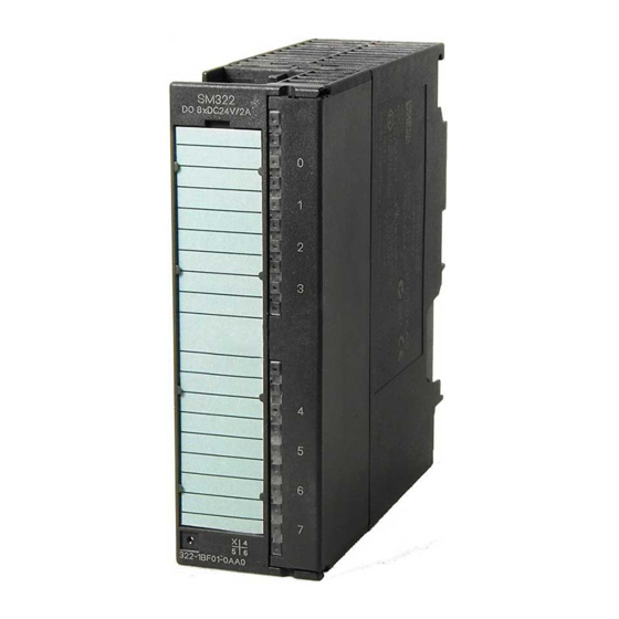
Page 15: The Fm 350-1 Hardware
Product Overview 1.3 The FM 350-1 hardware The FM 350-1 hardware Module view The figure shows the FM 350-1 module with a front connector and the expansion bus with the front panel closed. Figure 1-2 FM 350-1 module view Front Connector The FM 350-1 offers the following connection possibilities at the front connector: ●... - Page 16 Product Overview 1.3 The FM 350-1 hardware Front Connector Coding When you press the front connector from the wiring position to the operating position, the front connector coding engages. Thereafter, this front connector can only be attached to an FM 350-1 module. Coding Plug The coding plug is used to set the FM 350-1 to the encoder signals used.
- Page 17 Product Overview 1.3 The FM 350-1 hardware Diagnostics and Status LEDs The FM 350-1 has eight LEDs that can be used both for diagnostics and for indicating the status of the FM 350-1 and its digital inputs and outputs. Table 1- 3 LEDs with their labeling, color and function Label Color...
-
Page 18: The Software Of The Fm 350-1
Product Overview 1.4 The software of the FM 350-1 The software of the FM 350-1 Configuration Package To integrate the FM 350-1 into the S7-300, use the configuration package on the supplied CD . It includes: ● Parameterization software with parameterization interfaces ●... -
Page 19: Installing And Removing Fm 350-1
Installing and removing FM 350-1 Chapter Overview This chapter contains information on installing and removing the FM 350-1. ● You will learn what you must look out for when installing. ● You will get notes and hints on configuring, arranging and installing an FM 350-1. ●... -
Page 20: Preparing For Installation
Installing and removing FM 350-1 2.1 Preparing for installation Preparing for installation Important Safety Information There are important rules you must observe for integrating an S7-300 with an FM 350-1 into a plant or a system. These rules and directives are explained further in the /1/ manual. Vertical or Horizontal Arrangement Give preference to horizontal installation of the rack. -
Page 21: Installation Of The Fm 350-1
Installing and removing FM 350-1 2.2 Installation of the FM 350-1 Installation of the FM 350-1 Rules No special protection measures (ESD guidelines) are required for installing an FM 350-1. Required Tools You require a flat-bladed screwdriver 4.5 mm to install the FM 350-1. Setting the Signal Type (Coding Plug) Before mounting an FM 350-1 on the mounting rail, you must place the coding key in the correct position. - Page 22 Installing and removing FM 350-1 2.2 Installation of the FM 350-1 Procedure for the Installation How to mount the FM 350-1 on the mounting rail: 1. Switch the CPU to STOP. Switch off the power supply. 2. An bus connector is enclosed with the FM 350-1. Plug this into the bus connector of the module to the left of the FM 350-1.
-
Page 23: Removing Fm 350-1
Installing and removing FM 350-1 2.3 Removing FM 350-1 Removing FM 350-1 Rules No special protection measures (ESD guidelines) are required for removing the FM 350-1. Required Tools You require a flat-bladed screwdriver 4.5 mm to remove the FM 350-1. Procedure for Removal/Replacement of Modules How to remove the FM 350-1: 1. - Page 24 Installing and removing FM 350-1 2.3 Removing FM 350-1 FM 350-1 Counter module Manual, 05/2011, A5E03648639-01...
-
Page 25: Wiring The Fm 350-1
Wiring the FM 350-1 Chapter overview This chapter contains the following information on wiring the FM 350-1: ● Terminal assignment of the front connector. ● The functions of the connections. ● Notes on selecting cables. ● The steps to take when wiring the front connector. ●... -
Page 26: Pin Assignments Of The Front Connector
Wiring the FM 350-1 3.1 Pin assignments of the front connector Pin assignments of the front connector Front connector You connect the count signals, the digital inputs and digital outputs, the encoder supply and the auxiliary voltage and load voltage via the 20-pin front connector. The figure shows the front of the module, the front connector and the inside of the front panel with the pin assignments. - Page 27 Wiring the FM 350-1 3.1 Pin assignments of the front connector Pin Assignments of the Front Connector Table 3- 1 Pin assignments of the front connector Connection Name Input / Function Output Auxiliary voltage 24 V auxiliary voltage Auxiliary voltage ground 5 V encoder RS 422, 24 V encoder, 24 V pulse encoders...
- Page 28 Wiring the FM 350-1 3.1 Pin assignments of the front connector Auxiliary Voltage 1L+/1M Connect a direct voltage of 24 V to the 1L+ and 1M terminals for the voltage supply of the 5 V and 24 V encoders. An integral diode protects the module from reverse polarity of the auxiliary voltage. The module monitors the connection of the auxiliary voltage.
- Page 29 Wiring the FM 350-1 3.1 Pin assignments of the front connector Input Filters for 24 V Encoder Signals For the purpose of suppressing interference, you can parameterize input filters (RC elements) with a uniform filter time for the 24 V inputs A*, B* and N*. The following two input filters are available.
- Page 30 Wiring the FM 350-1 3.1 Pin assignments of the front connector Digital Outputs DO0 and DO1 The FM 350-1 features two digital outputs, DO0 and DO1, for directly triggering control processes. The digital outputs are supplied via the load voltage 2L+. The digital outputs are optically isolated from the bus of the S7-300 and the counter inputs.
-
Page 31: Wiring Front Connectors
Wiring the FM 350-1 3.2 Wiring front connectors Wiring front connectors Cables Here are some rules for you to observe when selecting cables: ● The cables for digital inputs DI Start, DI Stop and DI Set must be shielded. ● The cable for the counter signals must be shielded. ●... - Page 32 Wiring the FM 350-1 3.2 Wiring front connectors Terminal 2 (1M) of the front connector must have a low-resistance connection to the ground of the CPU. If you supply the encoder with an external voltage, you must also connect the ground of this external voltage with the CPU ground.
- Page 33 Wiring the FM 350-1 3.2 Wiring front connectors Wiring Proceed as follows when wiring the front connector: WARNING Injury to persons may result. If you wire the front connector of the FM 350-1 when the power is switched on, you are in danger of injury from electric shock.
-
Page 34: Module Status After Power On
Wiring the FM 350-1 3.3 Module status after power on Module status after power on Default setting Module status after power on and before any parameters were transferred: ● No gate - i.e., the gate is open ● Counter inputs with default setting for 5 V differential signals, track B not inverted; single evaluation (refer to the section Signal Evaluation (Page 166)) ●... -
Page 35: Programming Fm 350-1
Programming FM 350-1 Chapter Overview In this chapter, you will learn how to install and start parameterization interfaces. The parameterization interfaces have an integrated help function that supports you in parameterizing and starting up the FM 350-1. FM 350-1 Counter module Manual, 05/2011, A5E03648639-01... -
Page 36: Installing Parameterization Interfaces
● SIEMENS\STEP7\S7FCOUNT: Configuring software, Readme, Online help ● SIEMENS\STEP7\EXAMPLES:Examples ● SIEMENS\STEP7\S7MANUAL\S7FCOUNT: Getting Started, manuals Note If you selected a directory other than SIEMENS\STEP7 when you installed STEP 7, that directory will be entered. FM 350-1 Counter module Manual, 05/2011, A5E03648639-01... -
Page 37: Starting Parameterization Interfaces
Programming FM 350-1 4.2 Starting Parameterization Interfaces Starting Parameterization Interfaces Starting the Parameterization Interfaces 1. In HW Config: Select the FM 350-1 in your hardware catalog. Place the module on a vacant slot. 2. Double-click the FM 350-1. 3. Adapt the configuration of the FM 350-1 to your requirements. 4. - Page 38 Programming FM 350-1 4.2 Starting Parameterization Interfaces FM 350-1 Counter module Manual, 05/2011, A5E03648639-01...
-
Page 39: Programming The Fm 350-1
Programming the FM 350-1 Chapter Overview This chapter contains all the information necessary for programming the FM 350-1 in the S7-300. For linking the FM 350-1 into a user program, you are provided with STEP 7 blocks that make handling the desired functions easy for you. Table 5- 1 Blocks that are described in this chapter Block number... -
Page 40: Data Exchange Between The User Program And Fm 350-1
Programming the FM 350-1 5.1 Data exchange between the user program and FM 350-1 Data exchange between the user program and FM 350-1 Data Exchange You can access the FM 350-1 control and feedback interface from the user program either using standard FCs or with load and transfer commands. -
Page 41: The Function Fc Cnt_Ctl1 (Fc 2)
Programming the FM 350-1 5.2 The function FC CNT_CTL1 (FC 2) The function FC CNT_CTL1 (FC 2) Functionality The data required for the CNT_CTL1 function is stored in a DB on the CPU. The CNT_CTL1 function transfers data cyclically between this DB and the FM. Requirements ●... - Page 42 Programming the FM 350-1 5.2 The function FC CNT_CTL1 (FC 2) Example The following contains an example of how you can implement the transfer of the module address, the channel address, and the length of the user data to the DB in OB 100. The symbol table contains the following assignments for this example: CNT_CHAN1 DB 1...
- Page 43 Programming the FM 350-1 5.2 The function FC CNT_CTL1 (FC 2) CNT_CTL1 Function Parameters Table 5- 3 The Parameters of the CNT_CTL1 Function Name Declaration type Data type Meaning The user... The block... DB_NO INPUT DB number with the counter data enters polls SW_GATE...
- Page 44 Programming the FM 350-1 5.2 The function FC CNT_CTL1 (FC 2) Processing Jobs You make a job request for the FM 350-1 via the relevant FC parameters L_DIRECT, L_PREPAR, T_CMP_V1, T_CMP_V2, C_DOPARA, RES_SYNC, RES_ZERO, and OT_ERR_A. You must enter the appropriate values for the job (load value, comparison values, low limit, high limit, update time) before you call the FC in the DB.
- Page 45 Programming the FM 350-1 5.2 The function FC CNT_CTL1 (FC 2) Time Required to Transfer Values Table 5- 6 Time Required to Transfer Values Use of the FM 350-1 Time requirement Centralized At least 4 OB 1 cycles Distributed At least 5 PROFIBUS DP cycles (Non-isochronous mode) Distributed At transmission of...
- Page 46 Programming the FM 350-1 5.2 The function FC CNT_CTL1 (FC 2) DB address Parameters Meaning x = irrelevant Bit 7 Bit 6 Bit 5 Bit 4 Reaction of output DO1 Inactive Active from comparison value to overflow Active from comparison value to underflow Active on reaching the comparison value for pulse duration (up/down) Active on reaching the comparison value for pulse...
- Page 47 Programming the FM 350-1 5.2 The function FC CNT_CTL1 (FC 2) Table 5- 8 Parameters for Transferring Values in the DB (measuring modes) DB address Parameter Meaning 14.0 LOAD_VAL Low limit; load with function parameter L_PREPAR 14.0 LOAD_VAL Behavior of DO0; define with function parameter: C_DOPARA Bits 2 to 7 Bit 1 Bit 0...
-
Page 48: The Fc Cnt_Ctl2 Function (Fc 3)
Programming the FM 350-1 5.3 The FC CNT_CTL2 function (FC 3) The FC CNT_CTL2 function (FC 3) Functionality The functionality of FC CNT_CTL2 and FC CNT_CTL1 is basically the same. The differences between both are explained in the next sections. Use cases FC CNT_CTL2 can only be operated in an isochronous OB. -
Page 49: The Fc Diag_Inf Function (Fc 1)
Programming the FM 350-1 5.4 The FC DIAG_INF function (FC 1) The FC DIAG_INF function (FC 1) Functionality FC DIAG_INF reads data record DS1 from FM 350-1 and makes it available at the DB of FC CNT_CTL1. The transfer sequence in particular: ●... -
Page 50: Application Example
Programming the FM 350-1 5.5 Application example Application example Introduction The example below shows how the CNT_CTL1 function can be used for the functions `Transfer load value to FM 350-1' and `Start counter'. These functions are representative of all functions here. Prerequisites The load value to be transferred must have been entered in DB 1. - Page 51 Programming the FM 350-1 5.5 Application example Explanation CONT // Continue with normal execution L_DIRECT; // Load direct function is ready SW_GATE; // Open software gate; END: Description of the Symbols The table lists the symbols used in the example. You define your own symbol assignments in the S7 Symbol Table.
- Page 52 Programming the FM 350-1 5.5 Application example Description of the Procedure The load value of the channel is transferred to the FM 350-1 by means of the function call. When calling the CNT_CTL1 function, select either the L_DIRECT parameter or the L_PREPAR parameter.
-
Page 53: Technical Specifications Of The Blocks
Programming the FM 350-1 5.6 Technical specifications of the blocks Technical specifications of the blocks Table 5- 11 Technical Specifications for the Blocks Technical data FC CNT_CTRL FC CNT_CTL1 FC CNT_CTL2 FC DIAG_INF Block number FC 0 FC 2 FC 3 FC 1 Version Assignment in work... -
Page 54: Programming Fm 350-1 Without Fcs
Programming the FM 350-1 5.7 Programming FM 350-1 without FCs Programming FM 350-1 without FCs To operate FM 350-1 without FCs, you can operate and monitor the module directly using the control and check-back interface (user data interface.) User data have a length of 16 bytes, starting at the module's start address. Load commands allow you to read the check-back interface. - Page 55 Programming the FM 350-1 5.7 Programming FM 350-1 without FCs Offset to the start Parameters Meaning address x = irrelevant Bit 7 Bit 6 Bit 5 Bit 4 Reaction of output DO1 Inactive Active within the range from comparison value to overflow Active within the range from comparison value to underflow...
- Page 56 Programming the FM 350-1 5.7 Programming FM 350-1 without FCs Offset to the start Parameters Meaning address Bit 7: Reserve = 0 Byte 14 – – Bit 6: Reserve = 0 – Bit 5: Reserve = 0 – Bit 4: Reserve = 0 SET_DO1 Bit 3: Control bit DO1 SET_DO0...
- Page 57 Programming the FM 350-1 5.7 Programming FM 350-1 without FCs Explanation of the control bits for the count modes Table 5- 13 Explanation of the control bits for the count modes Control bits Explanation C_DOPARA Set this bit to change the function and reaction of DO0 and DO1, and the hysteresis and pulse duration.
-
Page 58: Checkback Interface For Count Modes
Programming the FM 350-1 5.7 Programming FM 350-1 without FCs 5.7.2 Checkback interface for count modes Checkback interface for count modes Table 5- 14 Checkback interface for count modes (inputs) Offset to the start Parameters Meaning address Bytes 0 to 3 LATCH_LOAD Load value which can be returned, or stored counter value for the latch function at the digital input... - Page 59 Programming the FM 350-1 5.7 Programming FM 350-1 without FCs Offset to the start Parameters Meaning address Bit 7: Latched state of comparator 2 Byte 14 STS_COMP2 STS_COMP1 Bit 6: Latched state of comparator 1 STS_CMP2 Bit 5: Status at output DO1 STS_CMP1 Bit 4: Status at output DO0 STS_STP...
- Page 60 Programming the FM 350-1 5.7 Programming FM 350-1 without FCs Description of the check-back bits for the count modes Table 5- 15 Description of the check-back bits for the count modes Acknowledgement bits Explanation DATA_ERR This bit indicates a faulty data (parameter assignment error) entry in the checkback interface. DIAG The bit will be set if diagnostics data record DS1 was updated to signal a diagnostics event.
- Page 61 Programming the FM 350-1 5.7 Programming FM 350-1 without FCs Acknowledgement bits Explanation STS_RES_ZERO Acknowledgement bit for resetting saved states in the acknowledgement bits STS_ZERO, STS_OFLW, STS_UFLW, STS_COMP1 and STS_COMP2 STS_RUN This bit corresponds to counter bit 2 0 = LED CR is off 1 = LED CR is lit STS_SET Status at digital input DI-Set...
-
Page 62: Control Interface For Measuring Modes
Programming the FM 350-1 5.7 Programming FM 350-1 without FCs 5.7.3 Control interface for measuring modes Control interface for measuring modes Parameter LOAD_VAL (bytes 0 to 3) has two different meanings: ● You set bit L_PREPAR to define the LOAD_VAL parameter as a low limit. ●... - Page 63 Programming the FM 350-1 5.7 Programming FM 350-1 without FCs Offset to the start Parameter Assignment address Bit 7: Reserve = 0 Byte 14 – – Bit 6: Reserve = 0 – Bit 5: Reserve = 0 – Bit 4: Reserve = 0 SET_DO1 Bit 3: Control bit DO1 SET_DO0...
- Page 64 Programming the FM 350-1 5.7 Programming FM 350-1 without FCs Description of the control bits for measuring modes Table 5- 17 Description of the control bits for measuring modes Control bits Explanation C_DOPARA Set this bit to change the reaction and function of DO0. The values at byte 0 are accepted as new function of DO0.
-
Page 65: Checkback Interface For The Measuring Modes
Programming the FM 350-1 5.7 Programming FM 350-1 without FCs 5.7.4 Checkback interface for the measuring modes Checkback interface for the measuring modes Table 5- 18 Checkback interface for the measuring modes (inputs) Offset to the start Parameter Assignment address Bytes 0 to 3 LATCH_LOAD Measured value... - Page 66 Programming the FM 350-1 5.7 Programming FM 350-1 without FCs Offset to the start Parameter Assignment address Bit 7: – Byte 14 – – Bit 6: – STS_CMP2 Bit 5: Status at output DO1 STS_CMP1 Bit 4: Status at output DO0 STS_STP Bit 3: Status at digital input DI-Stop STS_STA...
- Page 67 Programming the FM 350-1 5.7 Programming FM 350-1 without FCs Description of the acknowledgement bits for the measuring modes Table 5- 19 Description of the acknowledgement bits for the measuring modes Acknowledgement bits Explanation DATA_ERR This bit indicates that a data error was entered in the checkback interface. DIAG The bit will be set if diagnostics data record DS1 was updated to signal a diagnostics event.
-
Page 68: Operating The Interface With Full Acknowledgement Principle
Programming the FM 350-1 5.7 Programming FM 350-1 without FCs 5.7.5 Operating the interface with full acknowledgement principle Complete Acknowledgement Principle The complete acknowledgement principle is always used to control the FM 350-1 from the user program: Figure 5-4 Complete Acknowledgement Principle The sequence is as follows: 1. - Page 69 Programming the FM 350-1 5.7 Programming FM 350-1 without FCs Transferring values Values are also transferred using the complete acknowledgement principle with the FM 350- 1. If incorrect values are transferred, the FM 350-1 signals an operator error with the feedback bit OT_ERR.
- Page 70 Programming the FM 350-1 5.7 Programming FM 350-1 without FCs Table 5- 21 Simultaneous transfer of several values In the operating mode ..You can transfer at the same time Counting (Parameter LOAD_VAL) Load value (Parameter CMP_V1) Comparison value 1 ...
- Page 71 Programming the FM 350-1 5.7 Programming FM 350-1 without FCs Reading Back Values Values are read from the record DS 2 of the FM 350-1. You can also read this record with SFC 59 RD_REC. The DS 2 has the following structure: Table 5- 23 Data record DS 2 Address...
-
Page 72: Restart Coordination
Programming the FM 350-1 5.7 Programming FM 350-1 without FCs 5.7.6 Restart coordination Restart coordination FM 350-1 always sets the acknowledgement bit FM_NEUST when it performs a restart or detects a system startup If you do not use any FCs, coordinate the restart in the user program: Acknowledge the FM_NEUST bit by setting the NEUSTQ control bit. -
Page 73: Reaction To Cpu Stop And Cpu Stop To Run
Programming the FM 350-1 5.8 Reaction to CPU STOP and CPU STOP to RUN Reaction to CPU STOP and CPU STOP to RUN Behavior at CPU-STOP The behavior of the FM 350-1 when the higher-level controller fails is set using the Basic Parameters dialog box (shortcut menu Object Properties >... - Page 74 Programming the FM 350-1 5.8 Reaction to CPU STOP and CPU STOP to RUN FM 350-1 Counter module Manual, 05/2011, A5E03648639-01...
- Page 75 Commissioning FM 350-1 Chapter overview This chapter contains the checklists for commissioning FM 350-1. Those checklists help you ● check all working steps before you put the module into operation ● prevent faulty reactions of the module in runtime. FM 350-1 Counter module Manual, 05/2011, A5E03648639-01...
-
Page 76: Commissioning Fm 350-1
Commissioning FM 350-1 6.1 Working steps for mechanical installation Working steps for mechanical installation Checklist Use the checklist below to check and document the working steps for mechanical installation of the FM 350-1. Table 6- 1 Checklist of the steps during mechanical installation Working step Options/Procedure ✓... - Page 77 Commissioning FM 350-1 6.1 Working steps for mechanical installation Working step Options/Procedure ✓ 24 V pulse encoders with Connection Name Function direction level Encoder supply ground 24 VDC Encoder power supply 24 V Encoder signal A * Direction level B* Wire digital inputs and Digital inputs and digital Connection...
-
Page 78: Procedure For Assigning Parameters
Commissioning FM 350-1 6.2 Procedure for assigning parameters Procedure for assigning parameters Check lists Use the check lists below to check and document the working steps for parameterizing the FM 350-1. Table 6- 2 Check list for Count Modes Working step Options/Procedure ✓... - Page 79 Commissioning FM 350-1 6.2 Procedure for assigning parameters Working step Options/Procedure ✓ Configuring FM 350-1 in Gate control Gateless (continuous counting only) HW Config SW gate HW gate Latch Latch/retrigger Gate function Cancel Interrupt Latch Positive edge Negative edge Both edges. Determine the behavior of the digital inputs HW gate Level-controlled hardware gate...
- Page 80 Commissioning FM 350-1 6.2 Procedure for assigning parameters Working step Options/Procedure ✓ Configuring FM 350-1 in Output DO1 Inactive HW Config Active from Comparison value 2 to overflow In the S7 user program Active from Comparison value 2 to underflow Active on reaching comparison value for pulse duration (up/down) Active on reaching Comparison value 2 for pulse...
- Page 81 Commissioning FM 350-1 6.2 Procedure for assigning parameters Table 6- 3 Check list for Measuring Modes Working step Options/Procedure ✓ Configuring FM 350-1 in Select encoder HW Config 5-V encoder with Monitoring A + B + N symmetrical signals A + B None 24-V encoder with Max.
- Page 82 Commissioning FM 350-1 6.2 Procedure for assigning parameters Working step Options/Procedure ✓ Configuring FM 350-1 in Determine the behavior of the digital inputs HW Config HW gate Level-controlled hardware gate Edge-controlled hardware gate Minimum pulse width ≥2.5 μs ≥25 μs Determine the behavior of the digital outputs Output DO0 Low limit...
-
Page 83: Operating Modes, Parameters And Commands
Operating Modes, parameters and commands Chapter overview Contents of this chapter: ● A description of the operating modes ● A description of the commands ● Conditions and information to observe. FM 350-1 Counter module Manual, 05/2011, A5E03648639-01... -
Page 84: Basics On Calling Operating Modes, Settings And Commands
Operating Modes, parameters and commands 7.1 Basics on calling operating modes, settings and commands Basics on calling operating modes, settings and commands Calling operating modes, settings and commands ● You select the operating modes in the programming interfaces of FM 350-1. The parameter data are saved on the PG and transferred to the rack SDB. -
Page 85: Isynchronous Mode
7.2 Isynchronous mode Isynchronous mode Note Basic information on isochronous mode is available in the SIMATIC Isochronous Mode (http://support.automation.siemens.com/WW/view/en/15218045) function manual. Hardware requirements Requirements of operating FM 350-1 in isochronous mode: ● The CPU supports isochronous mode ● The DP master supports constant bus cycle times Principle of isochronous operation of FM 350-1 FM 350-1 supports non-isochronous and isochronous mode, depending on the configuration. -
Page 86: Count Modes
Operating Modes, parameters and commands 7.3 Count modes Count modes 7.3.1 Overview of the count modes Overview You define FM 350-1 functionality by setting a default mode of operation. The table shows an overview of the count modes. Table 7- 1 Count modes of FM 350-1 Designation Description... -
Page 87: Basic Principles
Operating Modes, parameters and commands 7.3 Count modes 7.3.2 Basic principles Load value The load value is the counter level from which the FM 350-1 starts the counting process. You can assign a load value LOAD_VAL to the FM 350-1 during operation. This will overwrite the starting count. - Page 88 Operating Modes, parameters and commands 7.3 Count modes Main Count Direction When you set a main count direction (up or down), you can limit the maximum count range to a smaller range by setting the high count limit. The set count range is then between 0 and the set high counter limit.
- Page 89 Operating Modes, parameters and commands 7.3 Count modes Commands for the Counting Modes You can apply five commands to the FM 350-1 counting process during operation: Table 7- 4 The FM 350-1 commands Name Description Open and close gate The counting process starts when a gate opens and ends when it closes. Setting the counter The counter can be set to the load value using various signals.
-
Page 90: Endless Counting
Operating Modes, parameters and commands 7.3 Count modes 7.3.3 Endless counting Overview In this operating mode, the FM 350-1 counts continuously from the count value: ● If the counter reaches the high limit when counting up and a further count pulse is received, it jumps to the low count limit and continues to count from there without any pulse losses. - Page 91 Operating Modes, parameters and commands 7.3 Count modes Selecting the Gate Function You can select the gate control in this mode. The following possibilities are available to you: ● Without gate (default) ● SW gate ● Hardware gate, level-controlled or edge-controlled Figure 7-1 Continuous counting with gate control Opening and Closing the Software Gate...
- Page 92 Operating Modes, parameters and commands 7.3 Count modes Terminating the Count with the Gate Stop Function You can also terminate the count when counting with the software gate or hardware gate by using the gate stop function. Set the GATE_STP input parameter of FC_CNT_CTL1 for this. Effects of the Latch Setting on the Counter at the Beginning of a Count Operation You can find information on this in the section command: Latch/retrigger (Page 127) and command: Latch (Page 130) in this section.
-
Page 93: Single Counting
Operating Modes, parameters and commands 7.3 Count modes 7.3.4 Single counting Overview In this operating mode the FM 350-1 counts once in the assigned main count direction and then stops the counting process automatically. You can assign the following behavior: ●... - Page 94 Operating Modes, parameters and commands 7.3 Count modes Single Counting - Main Count Direction Up In single counting mode with main count direction up, when the gate is opened, the FM 350-1 counts up or down from the load value until the high count limit is exceeded. If the high count limit is exceeded, the following occurs: ●...
- Page 95 Operating Modes, parameters and commands 7.3 Count modes Single Counting - Main Count Direction Down In single counting mode with main count direction down, when the gate is opened, the FM 350-1 counts up or down from the load value until the low count limit is exceeded. If the low count limit is under-run, the following occurs: ●...
- Page 96 Operating Modes, parameters and commands 7.3 Count modes Opening and Closing the Software Gate You open and close the software gate and set the counter to the load value with the SW_GATE input parameter of FC CNT_CTL1. Table 7- 8 Triggering the Opening/Closing of a SW Gate (Single Counting) Action ...Is initiated by...
- Page 97 Operating Modes, parameters and commands 7.3 Count modes Terminating the Count with the Gate Stop Function You can also terminate the count at any time with the gate stop function. Set the GATE_STP input parameter of the FC_CNT_CTL1 for this. FM 350-1 Counter module Manual, 05/2011, A5E03648639-01...
-
Page 98: Cyclic Count
Operating Modes, parameters and commands 7.3 Count modes 7.3.5 Cyclic count Overview In this operating mode, the FM 350-1 counts periodically when the gate is open. You can assign the following behavior: ● Periodic counting – No main count direction ●... - Page 99 Operating Modes, parameters and commands 7.3 Count modes Periodic Counting - Main Count Direction Up In periodic counting mode with main count direction up, when the gate is opened, the FM 350-1 counts up or down from the load value until the high count limit is exceeded. If the high count limit is exceeded, the following occurs: ●...
- Page 100 Operating Modes, parameters and commands 7.3 Count modes Periodic Counting - Main Count Direction Down In periodic counting mode with main count direction down, when the gate is opened, the FM 350-1 counts up or down from the load value until the low count limit is fallen below. If the low count limit is fallen below, the following occurs: ●...
- Page 101 Operating Modes, parameters and commands 7.3 Count modes Opening and Closing the Software Gate You open and close the software gate and set the counter to the load value with the SW_GATE input parameter of FC CNT_CTL1. Table 7- 11 Opening/Closing the Software Gate Action ...Is initiated by...
- Page 102 Operating Modes, parameters and commands 7.3 Count modes Behavior at the Count Limits If the counter ● has reached one of the count limits when counting without a main count direction, ● has reached the high count limit when counting with main count direction up, or ●...
-
Page 103: Counting Range
Operating Modes, parameters and commands 7.3 Count modes 7.3.6 Counting range Introduction There is a 32-bit wide count register on the module. With the Count range, you select whether the module is to count only in the positive range or whether the 32nd bit is interpreted as a sign bit thus allowing negative numbers to be represented. -
Page 104: Command: Open And Close Gate
Operating Modes, parameters and commands 7.3 Count modes 7.3.7 Command: Open and close gate Overview Gates of FM 350-1: ● A HW gate, level- or edge-triggered. ● A SW gate which you can open and close by setting control bits in the user program. Selecting a gate You define which gate you are going to use for the count in the mode interface. - Page 105 Operating Modes, parameters and commands 7.3 Count modes Edge-triggered opening and closing of the HW gate Figure 7-11 Edge-triggered opening and closing of the HW gate The edge-triggered HW gate is opened by setting a positive edge at digital input DI-Start. It is closed again by setting a positive edge at digital input DI-Stop.
- Page 106 Operating Modes, parameters and commands 7.3 Count modes SW gate status The status of the SW gate is indicated at the STS_SW_G bit in the DB of FC CNT_CTL1. Cancel and interrupt function of the gate In your gate function parameters, you can define whether the gate should cancel or interrupt the count.
- Page 107 Operating Modes, parameters and commands 7.3 Count modes Stopping the count using the gate stop function You can also stop the count by setting the gate stop function, regardless of the status or signals set at the SW gate. This is done by setting input parameter GATE_STP at FC_CNT_CTL1.
- Page 108 Operating Modes, parameters and commands 7.3 Count modes HW gate control: In HW gate control mode, the count starts or stops instantaneously when the gate opens or closes: Figure 7-16 Starting and stopping the count using the HW gate (HW_GATE) Hardware interrupt Opening and closing of a HW or SW gate can be used to trigger a hardware interrupt (see the chapter Triggering hardware interrupts (Page 156).)
-
Page 109: Behavior Of The Digital Outputs
Operating Modes, parameters and commands 7.3 Count modes 7.3.8 Behavior of the Digital Outputs Introduction You can store two comparison values (Comparison value 1 and 2) on the FM 350-1 for each counter. These comparison values are assigned to the two digital outputs (Comparison value 1: DO0, Comparison value 2: DO1). - Page 110 Operating Modes, parameters and commands 7.3 Count modes Setting and Resetting the Outputs If you set the behavior of an output to "Inactive", you can set and reset enabled outputs using the appropriate bits in the DB. Table 7- 18 Setting and Resetting the Outputs Output ...
- Page 111 Operating Modes, parameters and commands 7.3 Count modes Digital Output Behavior of the Digital Outputs Parameter Assignment The output is set to 1 for the period of the pulse duration when the counter reaches the comparison value while counting up. This requires either: No main count direction ...
- Page 112 Operating Modes, parameters and commands 7.3 Count modes Status of the Outputs and Status Bits The status of the two outputs is indicated by the green LEDs and the corresponding status bits in the DB. Table 7- 20 Output DO0 Comparison Enable bit Status bit...
- Page 113 Operating Modes, parameters and commands 7.3 Count modes Switching to Comparison Values Output DO1 switches at two comparison values if the following conditions are fulfilled: ● You have set the behavior of DO0 to "Inactive". ● You have set the behavior of DO1 to "Active for switching to comparison values". ●...
- Page 114 Operating Modes, parameters and commands 7.3 Count modes Figure 7-18 At the start of the counting process, V2 < V1 Pulse Duration You can set a pulse duration in order to adapt to the actuators (contactors, actuators, etc) used in your process. The pulse duration indicates how long outputs DO0 and DO1 are active when a comparison value is reached.
- Page 115 Operating Modes, parameters and commands 7.3 Count modes Figure 7-19 Reactions of an output for a pulse duration = 0 ms Boundary conditions for the behavior of the digital outputs If you assign the behavior of the digital outputs, you must observe the following boundary conditions.
- Page 116 Operating Modes, parameters and commands 7.3 Count modes Behavior of the Digital Outputs in Isochronous Mode In isochronous mode, the outputs DO0 and DO1 switch immediately after the comparison conditions are fulfilled, and are thus independent of the PROFIBUS DP cycle. Exception: If you have set the behavior of the digital outputs to "inactive"...
-
Page 117: Hysteresis
Operating Modes, parameters and commands 7.3 Count modes 7.3.9 Hysteresis Function principle of the hysteresis An encoder can come to rest at a particular position and then "oscillate" about this position. This causes the count value to fluctuate around a certain value. If there is a comparison value within this fluctuation range, for example, the associated output would be switched on and off in time with these fluctuations. - Page 118 Operating Modes, parameters and commands 7.3 Count modes If the count value overshoots/undershoots the range of the hysteresis (at counter value 2 or 8 in the example) the hysteresis ceases to be active. The comparator switches again according to its comparison conditions, i.e., in the example at counter value 5. Figure 7-20 Example showing the effect of the hysteresis Note...
- Page 119 Operating Modes, parameters and commands 7.3 Count modes Function principle of the hysteresis with "Active on reaching the comparison value for pulse duration (up/down)" setting The following figure shows an example of the effect of hysteresis. The diagram shows the differences in the output behavior when hysteresis values of 0 (= switched off) and 3 are assigned.
-
Page 120: Command: Setting The Counter
Operating Modes, parameters and commands 7.3 Count modes 7.3.10 Command: Setting the counter Overview If you want to start the count from a specific value (the load value), you must parameterize the signal that is to be used to set this counter to the load value. You can set the counter as follows: ●... - Page 121 Operating Modes, parameters and commands 7.3 Count modes Setting the Counter with an External Signal The L_PREPAR input parameter prepares a new load value. You can select two different external signals with which you can set a counter to the load value: ●...
- Page 122 Operating Modes, parameters and commands 7.3 Count modes Setting the Counter with DI Set The counter can be loaded with the load value by means of a rising pulse edge across DI Set. You can set the response of the FM 350-1 to a positive pulse edge across DI Set by means of the tags ENSET_UP and ENSET_DN in the DB of the FC CNT_CTL1 and by parameterization.
- Page 123 Operating Modes, parameters and commands 7.3 Count modes Single Setting with DI Set The following figure shows single setting of the counter with digital input DI Set. In the case represented here, only ENSET_UP is set, i.e., the counter is set during up counting. With the first rising pulse edge at digital input DI Set, the counter is set provided that ENSET_UP is similarly set.
- Page 124 Operating Modes, parameters and commands 7.3 Count modes Setting the Counter with DI Set and Zero Mark If you parameterize setting of a counter with the zero mark of the encoder, the counter will be set with the rising edge of the zero mark. Setting is performed only if DI Set is additionally set at the time of the rising pulse edge of the zero mark.
- Page 125 Operating Modes, parameters and commands 7.3 Count modes Single Setting of the Counter with DI Set and Zero Mark The following figure shows single setting of the counter with the zero mark. In the case represented here, only ENSET_UP is set, i.e., the counter is set during up counting. With the first rising pulse edge of the zero mark, the counter is set provided that ENSET_UP and DI Set are similarly set.
- Page 126 Operating Modes, parameters and commands 7.3 Count modes Multiple Setting of the Counter with DI Set and Zero Mark The following figure shows multiple setting of the counter with the zero mark. In the case represented here, only ENSET_UP is set, i.e., the counter is set during up counting. With every rising pulse edge of the zero mark, the counter is set provided that ENSET_UP and DI Set are set.
-
Page 127: Command: Latch / Retrigger
Operating Modes, parameters and commands 7.3 Count modes 7.3.11 Command: Latch / retrigger Introduction The latch/retrigger command can be used to save (latch) counter values using the edges of signals at digital input DI-Start. After each latching operation, the counter will be initialized with the load value, and resumes the count starting at the load value (retrigger.) Requirement Set the SW gate to enable this command. - Page 128 Operating Modes, parameters and commands 7.3 Count modes Function principle The counter function is enabled by opening the SW gate. The counter and latch values are assigned a start value. These values do not change by opening the SW gate. The first edge at input DI-Start starts the count at the load value.
- Page 129 Operating Modes, parameters and commands 7.3 Count modes Interrupting and canceling the command When you close the software gate, counting is interrupted (interrupting gate function); this means counting resumes at the most recent count value the next time the software gate opens.
-
Page 130: Command: Latch
Operating Modes, parameters and commands 7.3 Count modes 7.3.12 Command: Latch Introduction The latch command is used to save (latch) counter values using the edges at digital input DI-Start. This operation does not change the counter value. Requirement Set the SW gate to enable this command. The minimum interval between latch edges is 1 ms. - Page 131 Operating Modes, parameters and commands 7.3 Count modes Function principle The counter and latch values are assigned a start value. The count function starts when the SW gate has opened. The counter starts at the load value. The latch value is always equivalent to the counter value at the time the edge trigger is generated.
- Page 132 Operating Modes, parameters and commands 7.3 Count modes Canceling and terminating the command When you close the software gate, counting is cancelled (canceling gate function); this means counting begins again at the load value the next time the software gate opens. The current count is also stored at an edge at digital input DI-Start with a closed software gate and the count does not change.
-
Page 133: Command: Measure Edge Intervals
Operating Modes, parameters and commands 7.3 Count modes 7.3.13 Command: Measure edge intervals Introduction You can use this command to measure the time between two immediately successive edges at the Start DI digital input. Prerequisites The following prerequisites must be fulfilled in order to use this command: ●... -
Page 134: Measuring Modes
Operating Modes, parameters and commands 7.4 Measuring modes Measuring modes 7.4.1 Overview of measuring modes Overview You define FM 350-1 functionality by setting a default mode of operation. The table shows an overview of measuring modes. Table 7- 29 Measuring modes supported by FM 350-1 Name Description Frequency measurement... -
Page 135: Basics
Operating Modes, parameters and commands 7.4 Measuring modes 7.4.2 Basics Measuring principle FM 350-1 counts each positive edge of a pulse and assigns it a time value in µs. The dynamic measuring time is defined as the difference between two time values. At a pulse sequence with one or several pulses per update interval: Dynamic measuring time = time value of the last pulse in the current update interval minus... - Page 136 Operating Modes, parameters and commands 7.4 Measuring modes Measurement sequence FM 350-1 measures continuously. You define a specific update time in the parameter settings. The module returns the value "-1" until the first update time has expired. The first update time starts when the gate has opened.
- Page 137 Operating Modes, parameters and commands 7.4 Measuring modes The diagram below shows the principle of continuous measurement, based on the example of a frequency measurement. Figure 7-30 Principle of continuous measurement (example frequency measurement) FM 350-1 Counter module Manual, 05/2011, A5E03648639-01...
- Page 138 Operating Modes, parameters and commands 7.4 Measuring modes Limit monitoring On expiration of the update time, the module compares the measured value (frequency, speed or period) with the set low and high limits. If the module detects an underflow of the actual measured value (measured value < low limit), it sets the status bit STS_UFLW = 1.
- Page 139 Operating Modes, parameters and commands 7.4 Measuring modes Isochronous mode When operating in isochronous mode, FM 350-1 accepts the control signals output by the control interface at time T in each PROFIBUS DP cycle. As a result, all control operations are executed in isochronous mode and take effect at the time T .
-
Page 140: Frequency Measuring
Operating Modes, parameters and commands 7.4 Measuring modes 7.4.3 Frequency measuring Frequency Measurement In the frequency measurement operating mode, the FM 350-1 counts the pulses that occur within a dynamic measuring time. The value of the calculated frequency is made available in the unit 10 Hz. - Page 141 Operating Modes, parameters and commands 7.4 Measuring modes Limit Monitoring The following value ranges are permitted for limit value monitoring: Table 7- 33 Frequency Measurement: Value Ranges for Limit Monitoring Encoder type Low limit f High limit f 5-V encoders 0 to 499 999 999 ×...
- Page 142 Operating Modes, parameters and commands 7.4 Measuring modes Variable Values during Operation: ● Low limit (L_PREPAR) ● High limit (T_CMP_V1) ● Update time (T_CMP_V2) ● Function of digital output DO0 (C_DOPARA) (See the sections Behavior of the Digital Outputs (Page 153) , Control interface for the measuring modes (Page 62) and Checkback interface for the measuring modes (Page 65)) FM 350-1 Counter module Manual, 05/2011, A5E03648639-01...
-
Page 143: Speed Capture
Operating Modes, parameters and commands 7.4 Measuring modes 7.4.4 Speed capture Speed measurement In the RPM measurement operating mode, the FM 350-1 counts the pulses that are received from a tacho-generator within a dynamic measuring time, and calculates the speed from this value with the number of pulses per encoder revolution. - Page 144 Operating Modes, parameters and commands 7.4 Measuring modes Limit Monitoring The following value ranges are permitted for limit value monitoring: Table 7- 36 Speed capture: Value Ranges for Limit Monitoring Lower limit n Upper limit n 0 to 24 999 999 *10 /min +1 to 25 000 000 *10 /min...
- Page 145 Operating Modes, parameters and commands 7.4 Measuring modes Variable Values during Operation: ● Lower limit (L_PREPAR) ● Upper limit (T_CMP_V1) ● Update time (T_CMP_V2) ● Function of digital output DO0 (C_DOPARA) (See the sections Behavior of the Digital Outputs (Page 153) , Control interface for the measuring modes (Page 62) and Checkback interface for the measuring modes (Page 65)) FM 350-1 Counter module Manual, 05/2011, A5E03648639-01...
-
Page 146: Period Measurement
Operating Modes, parameters and commands 7.4 Measuring modes 7.4.5 Period measurement Period measurement In period measurement mode, the FM 350-1 indicates the dynamic measuring time as a period. If the period is less than the update time, then an average is calculated for the period. The value of the calculated period is displayed in units 1 μs or 1/16 μs. - Page 147 Operating Modes, parameters and commands 7.4 Measuring modes Limit Monitoring The following value ranges are permitted for limit value monitoring: Table 7- 39 Value Range for Limit Monitoring at a Resolution of 1 µs Low limit T High limit T 0 to 119 999 999 μs +1 to 120 000 000 μs Table 7- 40...
- Page 148 Operating Modes, parameters and commands 7.4 Measuring modes Function of Digital Output DO0 You can choose between the following functions for digital output DO0: ● No comparison (no switching by limit value monitoring) ● Measured value outside limits ● Measured value under low limit ●...
-
Page 149: Command: Open And Close Gate
Operating Modes, parameters and commands 7.4 Measuring modes 7.4.6 Command: Open and close gate Overview Gates of FM 350-1: ● A HW gate, level- or edge-triggered. ● A SW gate which you can open and close by setting control bits in the user program. Selecting a gate You define which gate you are going to use for the measurement in the mode interface. - Page 150 Operating Modes, parameters and commands 7.4 Measuring modes Edge-triggered opening and closing of the HW gate Figure 7-36 Edge-triggered opening and closing of the HW gate You open the HW gate to start the measurement by setting a positive edge at digital input DI-Start.
- Page 151 Operating Modes, parameters and commands 7.4 Measuring modes Opening and closing the SW gate Figure 7-37 Opening and closing the SW gate You open the SW gate to start the measurement by setting input parameter SW_GATE at FC CNT_CTL1. You close the SW gate to stop the measurement by resetting SW_GATE. The measured value which is valid at the time the SW gate is closed is retained at the checkback interface.
- Page 152 Operating Modes, parameters and commands 7.4 Measuring modes Gate control in isochronous mode SW gate control: You control operations using the SW gate by setting and resetting the SW_GATE control bit in the user program. The measurement starts when the control bit is set, and stops at the time T in the next PROFIBUS DP cycle when the control bit is reset: Figure 7-38...
-
Page 153: Behavior Of The Digital Outputs
Operating Modes, parameters and commands 7.4 Measuring modes 7.4.7 Behavior of the Digital Outputs Introduction You can store an upper and a lower limit value for the frequency measurement, RPM measurement or cycle duration measurement. This will be activated when digital output DO0 is exceeded. - Page 154 Operating Modes, parameters and commands 7.4 Measuring modes Behavior of the Digital Outputs Digital output DO0 For digital output DO0, you can set 4 possible reactions to reaching the limit values. The various options are shown in the table below. Table 7- 44 Behavior of Digital Output DO0 Parameterization of...
- Page 155 Operating Modes, parameters and commands 7.4 Measuring modes Status of the Outputs and Status Bits The status of the two outputs is indicated by the green LEDs and the corresponding status bits in the DB. Table 7- 45 Output DO0 Limit values Enable bit Status bit...
-
Page 156: Triggering Of A Hardware Interrupt
Operating Modes, parameters and commands 7.5 Triggering of a Hardware Interrupt Triggering of a Hardware Interrupt Introduction With the FM 350-1, you can set which events are to initiate a hardware interrupt. For this purpose, parameterize the FM 350-1 interrupts in the parameterization screens. What is a Hardware Interrupt? If you want to program a response to a specific event independently of the CPU cycle, each counter of the FM 350-1 can initiate a hardware interrupt. - Page 157 Operating Modes, parameters and commands 7.5 Triggering of a Hardware Interrupt Enabling the Hardware Interrupt You enable the interrupts for the module in the parameterization screens when configuring the hardware and you decide whether the module is to initiate a diagnostics interrupt and/or a hardware interrupt.
- Page 158 Operating Modes, parameters and commands 7.5 Triggering of a Hardware Interrupt Lost Hardware Interrupt If an event occurs that is to initiate a hardware interrupt and the same previous event has not yet been acknowledged, no further hardware interrupt is initiated; the hardware interrupt is lost.
-
Page 159: Encoder Signals And Their Evaluation
Encoder signals and their evaluation Chapter overview This chapter describes: ● which encoders you can connect to the counter module ● the time profile of the encoder signals ● the multiple evaluation of encoder signals by the counter module ● how the module monitors the various encoder signals ●... -
Page 160: Encoders Which Can Be Connected
Encoder signals and their evaluation 8.1 Encoders which can be connected Encoders which can be connected Introduction The counter module can process rectangular count signals which were generated by incremental encoders or pulse generators. Incremental encoders scan a barcode to generate rectangular electrical pulses. They differ in terms of pulse amplitude and number of signals. -
Page 161: 5-V Differential Signals
Encoder signals and their evaluation 8.2 5-V differential signals 5-V differential signals Count signals of 5-V incremental encoders RS422 signals returned by the 5-V incremental encoder to the module: ● A and /A ● B and /B ● N and /N The signals /A, /B and /N are the inverted signals of A, B and N. - Page 162 Encoder signals and their evaluation 8.2 5-V differential signals Monitoring encoder signals The module monitors the cable connection, and detects wire-break or short-circuit. You can define which of the three signal pairs to include in monitoring in your program. There is no need to wire any unused signal pairs, if you have disabled the corresponding diagnostics functions in the program (monitoring.) An error state at all three signals indicates a defective encoder, or a short-circuit at the "5.2 V DC"...
-
Page 163: 24-V Signals
Encoder signals and their evaluation 8.3 24-V signals 24-V signals Count signals returned by 24-V encoders 24-V incremental encoders The 24-V incremental encoder returns the 24-V signals A*, B* and N* to the module. The A* and B* signals are phase-shifted by 90°. 24-V signals are marked with an asterisk "*"... - Page 164 Encoder signals and their evaluation 8.3 24-V signals 24-V pulse encoders without/with direction signal Encoders such as proximity switches (BERO) or light barriers return only a count signal which you wire to terminal A* of the front connector. in additional, you can wire a signal for direction detection to terminal B* of the relevant counter.
- Page 165 Encoder signals and their evaluation 8.3 24-V signals Input filters for the 24-V count inputs For the purpose of suppressing interference, you can parameterize input filters with a uniform filter time for the 24 V inputs A*, B* and N* and for the digital inputs. Input filters available: Table 8- 3 Input filters...
-
Page 166: Signal Evaluation
Encoder signals and their evaluation 8.4 Signal evaluation Signal evaluation Overview The counter module supports the count of signal edges. It usually evaluates the edge at A (A*) (single evaluation). Options in the program of increasing the resolution: ● Single evaluation ●... - Page 167 Encoder signals and their evaluation 8.4 Signal evaluation Double evaluation Double evaluation refers to the evaluation of the positive and negative edges of signal A. The logic level at signal B determines the count direction, i.e. the up or down count pulse. The diagram shows the double evaluation of signals: Figure 8-5 Double evaluation...
- Page 168 Encoder signals and their evaluation 8.4 Signal evaluation FM 350-1 Counter module Manual, 05/2011, A5E03648639-01...
-
Page 169: Db Assignments
DB assignments DB for FC CNT_CTL1 All data belonging to a module channel are stored in the DB of FC CNT_CTL1. The data structure and length of the DB are defined by UDT2. You must assign the valid data listed below to the DB before assigning module parameters. - Page 170 DB assignments Address Variable Data type Start value Comment Count Measuring Control interface 26.0 A_BIT0_0 BOOL FALSE Reserved Reserved 26.1 A_BIT0_1 BOOL FALSE Reserved Reserved 26.2 A_BIT0_2 BOOL FALSE Reserved Reserved 26.3 A_BIT0_3 BOOL FALSE Reserved Reserved 26.4 A_BIT0_4 BOOL FALSE Reserved Reserved...
- Page 171 DB assignments Address Variable Data type Start value Comment Count Measuring Transfer area for read values 30.0 LATCH_LOAD DINT Actual load or latch value Actual measured value (read (read user) user) 34.0 ACT_CNTV DINT Actual count value Actual count value (read user) (read user) Error numbers...
- Page 172 DB assignments Address Variable Data type Start value Comment Count Measuring 44.0 STS_SET BOOL FALSE Status digital input DI-Set Status digital input DI-Set (read user) (read user) 44.1 STS_LATCH BOOL FALSE New latch value (only in isochronous mode) 44.2 STS_STA BOOL FALSE Status digital input DI-Start...
- Page 173 DB assignments Address Variable Data type Start value Comment Count Measuring 56.0 SUB_MDL_ERR BOOL FALSE Wrong/missing interface Wrong/missing interface module module 56.1 COMM_FAULT BOOL FALSE Communication error Communication error 56.2 MDL_STOP BOOL FALSE RUN/STOP mode indication RUN/STOP mode indication 56.3 WTCH_DOG_F BOOL FALSE...
- Page 174 DB assignments Address Variable Data type Start value Comment Count Measuring 62.0 CH1_SIGA BOOL FALSE Channel 1, signal A error Channel 1, signal A error 62.1 CH1_SIGB BOOL FALSE Channel 1, signal B error Channel 1, signal B error 62.2 CH1_SIGZ BOOL FALSE...
-
Page 175: Errors And Diagnostics
Errors and diagnostics Chapter overview Operator errors, faulty wiring or contradictory parameters (position of the coding plug does not match parameter data) can lead to errors which the module must indicate. Error classes of the module: ● Errors indicated by the group error LED to report internal and external module errors. ●... -
Page 176: Error Display Via The Group Error Leds
Errors and diagnostics 10.1 Error Display via the Group Error LEDs 10.1 Error Display via the Group Error LEDs Where is the Fault Indicated? If the red group error LED lights up, a fault has occurred either on the module (internal fault) or at the cable connections (external fault). -
Page 177: Triggering Diagnostics Interrupts
Errors and diagnostics 10.2 Triggering diagnostics interrupts 10.2 Triggering diagnostics interrupts Definition of a diagnostics interrupt You can determine reactions to internal or external errors in the user program, by programming a diagnostics interrupt which interrupts cyclic program execution on the CPU, and triggers a call of diagnostics interrupt OB 82. - Page 178 Errors and diagnostics 10.2 Triggering diagnostics interrupts Diagnostics data records DS0 and DS1 The information showing the event which has triggered a diagnostics interrupt is written to the diagnostics data records DS0 and DS1. Diagnostics data record DS0 consists of four bytes, and DS1 of 16 bytes.
- Page 179 Errors and diagnostics 10.2 Triggering diagnostics interrupts Byte Meaning Remarks Event ID 0...3 Type class Always assigned the value 8 Channel information Always assigned the value 1 Time monitoring (watchdog) triggered Module defective, or heavy interference 8:x:33 RAM defective Module defective, or heavy interference 8:x:43 Hardware interrupt lost Check the configuration.
-
Page 180: Data Error
Errors and diagnostics 10.3 Data error 10.3 Data error Data error events FM 350-1 checks all new parameters it receives. The module reports any errors returned in this check. Where data errors are indicated FC CNT_CTL1 enters the data errors and the error number in the DB of FC CNT_CTL1. You can access this data word in the user program using the variable identifier `DA_ERR_W'. - Page 181 Errors and diagnostics 10.3 Data error Meaning Undershoot, or load value out of limits. Overshoot, or comparison value 1 out of limits Update time or comparison value 2 out of limits Pulses per encoder revolution out of limits How to acknowledge data errors Correct the parameter values according to specifications.
-
Page 182: Operator Error
Errors and diagnostics 10.4 Operator error 10.4 Operator error Operator errors events Operator errors develop as a result of improper operation of the module caused by the incorrect input of control signals. Objects which indicate operator errors FC CNT_CTL1 enter the operator error numbers in the DB. FC CNT_CTL1 sets output parameter OT_ERR to indicate the occurrence of an operator error. -
Page 183: Technical Data
Technical data 11.1 General technical specifications These general technical specifications are described in the manual /1/: ● Standards and certifications ● Electromagnetic compatibility ● Shipping and storage conditions ● Mechanical and climatic environment conditions ● Specifications for insulation tests, protection class, degree of protection, and rated voltage ●... -
Page 184: Technical Data
Technical data 11.2 Technical data 11.2 Technical data Technical specifications of FM 350-1 Dimensions and weight Dimensions W x H x D (mm) 40 x 125 x 120 Weight approx. 250 g Current, voltage and power Current consumption (from backplane bus) max. - Page 185 Technical data 11.2 Technical data Digital outputs Supply voltage 2L+ / 2M Electrical isolation Yes, against all other circuits, except digital inputs Output voltage High signal "1" min. 2L+ - 1.5 V Low signal "0" max. 3 V Switching current Rated value 0.5 A...
- Page 186 Technical data 11.2 Technical data FM 350-1 Counter module Manual, 05/2011, A5E03648639-01...
-
Page 187: Replacement Parts
Replacement parts Spare parts The table lists all spare parts of the S7-300 system. You can order these separately or in addition to your FM 350-1. S7-300 parts Order number Bus connector 6ES7390-0AA00-0AA0 Labeling strip 6ES7392-2XX00-0AA0 Slot number label 6ES7912-0AA00-0AA0 Front connector (20-pin) screw-in contacts 6ES7392-1AJ00-0AA0 Front connector (20-pin) spring-loaded contacts... - Page 188 Replacement parts FM 350-1 Counter module Manual, 05/2011, A5E03648639-01...
-
Page 189: References
The table below lists all manuals to which reference is made in the present manual. Title SIMATIC; S7-300 CPU 31xC and CPU 31x: Installation (http://support.automation.siemens.com/WW/view/en/13008499) SIMATIC; System and Standard Functions for S7-300/400 (http://support.automation.siemens.com/WW/view/en/44240604) Modifying the System during Operation via CiR... - Page 190 References FM 350-1 Counter module Manual, 05/2011, A5E03648639-01...
-
Page 191: Glossary
Glossary Asymmetrical signals Refers to two pulse sequences, phase-shifted by 90°, and with zero mark signal where applicable. Configuration Assignment of modules to racks, slots and addresses. Users configuring the hardware fill out a configuration table in STEP 7. Double evaluation In this mode, the module evaluates all positive edges of the pulses at track A and B of an incremental encoder. - Page 192 Glossary Incremental encoder Incremental encoders are used to record distance, position, velocity, speed or weight units by counting small increments. Increments per encoder revolution Defines the number of increments the encoder outputs per revolution. The "output disable" (OD) signal is used in STOP and HOLD state to force all modules of an S7 automation system to safe state.
- Page 193 Glossary Sinking output Encoder output which returns an active low signal to 0 V (ground) Sourcing output Sourcing output of the encoder which returns an active high signal +24 V. STOP STOP as an international term, for example, as an operating command. STOPP STOPP (German spelling) as a term used in the manual to define an action which is not a command.
- Page 194 Glossary FM 350-1 Counter module Manual, 05/2011, A5E03648639-01...
-
Page 195: Index
Index Checkback interface Count modes, 58 Measuring modes, 65 Checklist Mechanical installation, 76 0 to +32 bit counting range, 103 Coding plug Correct position, 21 Command Latch, 130 Latch/retrigger, 127 24 V DC encoder supply, 28 Measuring times, 133 24 V encoder signals, 28 Open and close gate, 104, 149 24-V encoder signals, 28, 163 Setting the counter, 120... - Page 196 Index Data error, 180 FC CNT_CTL1, 41 Data exchange Parameters, 43 Using the control and feedback interface, 40 FC CNT_CTL2, 48 DB parameters for counting FC DIAG_INF, 49 Transferring values, 45 DB parameters for measuring Technical data, 53 Transferring values, 46 Feedback interface DI Set, 29 Data exchange, 40...
- Page 197 Index Pulse duration Default value, 114 Labeling strips, 16 Range of values, 114 Latch, 130 Latch/retrigger, 127 LED displays Meaning, 17 Load value, 10, 120 Quadruple evaluation, 167 Load voltage, 30 Restart coordination, 72 Main application area, 13 RPM measurement mode, 143 Maximum number of FM 350-1 used, 20 Measure...
- Page 198 Index Transferring values DB parameters for counting, 45 DB parameters for measuring, 46 Time required (with function), 45 Time required (without function), 70 With function, 44 Without function, 69 Underflow, 103 Values Readback, 71 Version, 16 Voltage supply The encoder, 28 Wire end ferrule, 32 Zero pass, 103 FM 350-1 Counter module...
Need help?
Do you have a question about the SIMATIC S7-300 FM 350-1 and is the answer not in the manual?
Questions and answers