Table of Contents
Advertisement
Quick Links
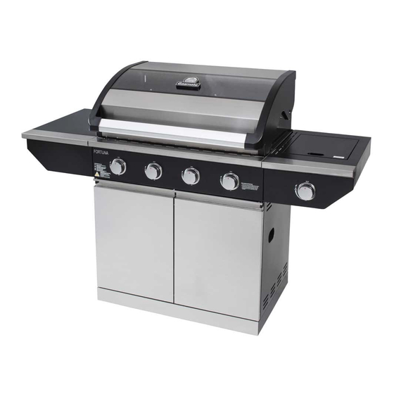
4 BURNER - BQ1070F
6 BURNER - BQ1071F
Deluxe BBQ featuring vitreous enamel body
Stainless steel hood includes glass window
and temperature gauge
Stylish cabinet
Rotary ignition
Important: Retain these instructions for future use
Gasmate® is a registered trademark of
Sitro Group Australia Pty Ltd. www.gasmate.com.au
Aber, N.Z. www.gasmate.co.nz
Stainless steel tube burners
Satin enamel cast iron grill and reversible hotplate
Operates on Universal L.P.G.
Gas certified to Australian Standards
03610 07/17
Advertisement
Table of Contents

Related Manuals for Gasmate BQ1070F


Summary of Contents for Gasmate BQ1070F
- Page 1 Operates on Universal L.P.G. Stylish cabinet Gas certified to Australian Standards Rotary ignition Important: Retain these instructions for future use 03610 07/17 Gasmate® is a registered trademark of Sitro Group Australia Pty Ltd. www.gasmate.com.au Aber, N.Z. www.gasmate.co.nz...
-
Page 2: Read Me First
READ ME FIRST GAS LEAK TESTING It is important that you leak test the BBQ before first use and every time the gas cylinder is refilled and reconnected to the BBQ. To Complete Leak Test • Make sure all the control knobs are OFF. •... -
Page 3: General Information
GENERAL INFORMATION Hose & Regulator Safety The regulator and hose assembly supplied with the IMPORTANT barbecue are suitable for Propane Gas or Universal Read these instruction carefully prior to use. L.P.G. only. Familiarise yourself with the appliance before A gas regulator adjusted to have an outlet pressure of connecting it to it’s gas container. -
Page 4: For Your Safety
GENERAL INFORMATION FOR YOUR SAFETY • Never test for gas leaks with a lit match or open flame. Never light barbecue with hood closed or Failure to comply with these instructions could before checking to ensure the burner tubes are result in a fire or explosion which could cause fully seated over gas valve orifices. -
Page 5: Care And Maintenance
CARE & MAINTENANCE Location of your Barbecue As with all appliances, proper care and maintenance will keep them in top operating condition and prolong DO NOT use your barbecue in garages, porches, sheds, their life. Your new gas barbecue is no exception. By breezeways, or other enclosed areas. - Page 6 BQ1070F - EXPLODED DIAGRAM...
- Page 7 BQ1070F - PARTS LIST 1 Hood & Body Assy. x 1 2 Warming Rack x 1 3 Flame Tamer x 2 4 Cooking Grill x 1 5 Hot Plate x 1 6 Side Shelf Assy. x 1 7 Side Burner Assy. x 1...
- Page 8 BQ1071F - EXPLODED DIAGRAM...
- Page 9 BQ1071F - PARTS LIST 1 Hood & Body Assy. x 1 2 Warming Rack x 1 3 Flame Tamer x 4 4 Cooking Grill x 2 5 Hot Plate x 1 6 Side Shelf Assy. x 1 7 Side Burner Assy. x 1 8 Side Burner Grill x 1 9 Side Burner x 1 10 Drip Tray x 1...
-
Page 10: Assembly Instructions
ASSEMBLY INSTRUCTIONS Note: The 4 burner model is shown here. Follow these instructions for 6 burner model also. Before assembling the barbecue, read these instructions carefully. Assemble the barbecue on a flat, clean surface. The barbecue is heavy. Remove any transit protection material. Tools Required: Phillips Head Screwdriver &... - Page 11 STEP 3 Use 5pcs M6*12 screw (28) to fix the back panel (18) onto base panel, cabinet left side panel and cabinet right side panel. STEP 4 Use 4pcs M6*12 screw (28) to fix the cabinet beam assy (17) between two cabinet side panels, as shown.
- Page 12 STEP 5 Use 9pcs M6*12 screw (28) to fix the cabinet top panel (13) onto cabinet side top panels (14) and back panel, then use 4pcs M5*10 screw (26) to fix the Cabinet Side Top Panel on cabinet side panels, as shown. STEP 6 To fit the cabinet doors (22, 23), insert the fixed upper pin into the bracket as shown in the picture, then insert the bottom pin into the base panel, as shown.
- Page 13 STEP 7 Rest the Hood & body assy (1) carefully onto the cabinet. Insert 4pcs M6*12 screw (28) through 4pcs washer-C (25) to fix the body assembly onto the cabinet as shown. STEP 8 Loosen 2pcs preset M6*12 screw of left side shelf assy (6) by leaving about 5mm of thread exposed, hang the side shelf onto the screws and then tighten the screws.
- Page 14 STEP 9.1 Loosen 2pcs preset M6*12 screw of right side burner assy (7) by leaving about 5mm of thread exposed, hang the side burner onto the screws and then tighten the screws. Use 2pcs M6*12 screw (28) fix the side burner support onto the body, and use 2pcs M5*10 screw (26) to fix the side fascia to the end of BBQ control panel fascia, as shown.
- Page 15 STEP 10 Place the grease cup (10) at bottom of drip tray (11) then insert into the slot at the back of BBQ. STEP 11 Place 2pcs of flamer tamer (3) on the top of left side 2 burners, and place the 1pc cooking grill (4) and hot plate (5) and warming rack (2) into the body assembly as shown in the picture.
-
Page 16: Bbq Specifications
STEP 12 Open the cabinet door, and let the hose go through the cabinet side panel to connect to the cylinder. Open the cylinder valve and leak test all connections with a soapy water solution. Note: 4B Shown BBQ SPECIFICATIONS Overall Barbecue Dimensions - Including Side Shelves Barbecue Hood... -
Page 17: General Assembly
GENERAL ASSEMBLY CONNECTING & DISCONNECTING LIGHTING PROCEDURE TO GAS SOURCE Burner Operation & Ignition System Check Familiarise yourself with the general information and 1. With cylinder valve in ‘OFF’ position push and rotate safety guidelines located at the front of this manual. the control knobs. -
Page 18: Operation
OPERATION Burner Operation & Ignition System Check Problem Possible Reason Solution Valve on gas bottle closed Open valve on gas bottle Control knob is closed Turn knob to high when lighting Burner will not ignite Igniter is faulty Use a long barbecue match. Insert through the hole at side of barbecue Burner has gone out Check that the gas bottle is not empty and... -
Page 19: Safe Appliance Locations
SAFE APPLIANCE LOCATIONS This appliance shall only be used in an above ground open-air situation with natural ventilation, without stagnant areas, where gas leakage and products of combustion are rapidly dispersed by wind and natural convection. Any enclosure in which the appliance is used shall comply with the following: An enclosure with walls on all sides, but at least one permanent opening at ground level and no overhead cover. - Page 20 For any queries or assistance call Customer Service (Australia Only) 1300 174 876 Hours of operation: Monday to Friday 8am - 5pm EST Do not return to place of purchase. Keep your purchase receipt, this will be required to make any claims under the 12 month warranty.
Need help?
Do you have a question about the BQ1070F and is the answer not in the manual?
Questions and answers