Table of Contents
Advertisement
Quick Links
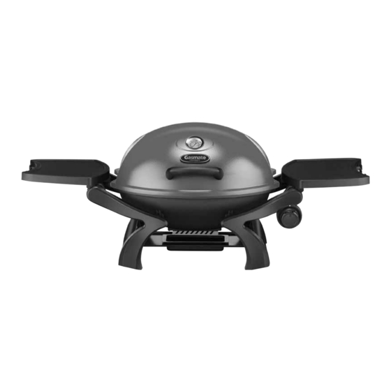
ODYSSEY ONE BURNER
PORTABLE BBQ
Model No. BQ1060MG
Powerful 11MJ/h stainless steel burner for true
BBQ performance
Rotary ignition for easy lighting
Generous cooking area of 1419cm
Satin enamel cast iron cooking surface – ½ grill
and ½ hotplate – easy to cook on and wash up
Durable die cast aluminium bowl and hood
2
Important: Retain these instructions for future use.
Gasmate® is a registered trademark of
Sitro Group Australia Pty Ltd www.gasmate.com.au
Aber, N.Z. www.gasmate.co.nz
Integrated temperature gauge - a must when roasting
Convenient side shelves for easy food preparation and
cooking - when not in use, they can be removed
High dome hood – 20cm – allows you to roast easily
Supplied with hose and regulator so it's ready to
use with a POL gas cylinder
Gas certified to Australian Standards
04303 05/21
Advertisement
Table of Contents

Related Manuals for Gasmate Odyssey BQ1060MG


Summary of Contents for Gasmate Odyssey BQ1060MG
- Page 1 POL gas cylinder Durable die cast aluminium bowl and hood Gas certified to Australian Standards Important: Retain these instructions for future use. Gasmate® is a registered trademark of 04303 05/21 Sitro Group Australia Pty Ltd www.gasmate.com.au Aber, N.Z. www.gasmate.co.nz...
-
Page 2: Read Me First
READ ME FIRST GAS LEAK TESTING It is important that you leak test the BBQ before first use and every time the gas cylinder is refilled and reconnected to the BBQ. To Complete Leak Test • Make sure all the control knobs are OFF. •... -
Page 3: General Information
GENERAL INFORMATION Hose & Regulator Safety The regulator and hose assembly supplied with the IMPORTANT barbecue are suitable for Propane Gas or Universal Read these instructions carefully prior to use. L.P.G. only. Familiarise yourself with the appliance before A gas regulator adjusted to have an outlet pressure of connecting it to it’s gas container. - Page 4 GENERAL INFORMATION FOR YOUR SAFETY • Never lean over cooking surface when lighting. • Never alter or modify the regulator or gas supply Failure to comply with these instructions could assembly. result in a fire or explosion which could cause serious bodily injury, death or property damage.
-
Page 5: Protect Children
Location of your Barbecue DO NOT use your barbecue in garages, porches, sheds, breezeways, or other enclosed areas. Your barbecue is to be used OUTDOORS. The barbecue is not intended to be installed in or on recreational vehicles and/or boats and should not be placed under any surface that will burn. -
Page 6: Exploded Diagram
EXPLODED DIAGRAM PARTS LIST Part Description Part Description Heat Insulator Temperature Gauge Support Leg Left Lid Handle Support Leg Right Cooking Grate Fat Cup Hot Plate Fat Cup Support Burner Side Shelf Bowl Stepped Washer HARDWARE AA : 8PCS BB : 8PCS CC : 2PCS DD : 6PCS Ø6 x Ø13 x 1.0... - Page 7 ASSEMBLY INSTRUCTIONS Remove any transit protection material. STEP 1 Attach the temperature gauge and lid handle using the fasteners as shown. AA x 2 BB x 2 CC x 2 FF x 1 GG x 1 STEP 2 Locate the burner into the bowl and secure with the fasteners as shown. DD x 2 BB x 2 AA x 2...
- Page 8 STEP 3 Join the left and right leg supports with the fat cup support using the fasteners as shown. DD x 4 BB x 4 AA x 4...
-
Page 9: Ignition Cable
STEP 4 Position the bowl and secure using the fasteners as shown, ensure the screw (EE) is inserted into the stepped plastic washer (N). Attach the ignition cable to the back of the gas valve. N x 4 EE x 4 Ignition Cable IMPORTANT! Ensure the burner is located... - Page 10 STEP 5 Locate the lid and attach using the fasteners as shown. HH x 2 II x 2 STEP 6 Position the hot plate and grate as shown.
- Page 11 STEP 7 Position the side shelves as shown.
-
Page 12: Lighting Procedure
GENERAL INFORMATION CONNECTING & DISCONNECTING LIGHTING PROCEDURE TO GAS SOURCE Burner Operation & Ignition System Check Familiarise yourself with the general information and 1. With cylinder valve in ‘OFF’ position check the piezo safety guidelines located at the front of this manual. igniter by pushing in and rotating the control knob Check anti-clockwise. -
Page 13: Operation
OPERATION BURNER OPERATION & IGNITION SYSTEM CHECK Problem Possible Reason Solution Control knob is closed Turn knob to high when lighting Piezo igniter is faulty Use a long barbecue match inserted through Burner will not ignite the hole on under side of barbecue Piezo igniter electrode not aligned Ensure the electrode tip is 3-4mm away from the burner tube... -
Page 14: Care And Maintenance
CARE & MAINTENANCE Cleaning the Cooking Surface As with all appliances, proper care and maintenance will keep them in top operating condition and prolong After cooking, turn burner control to ‘OFF’ and let their life. Your new gas barbecue is no exception. By barbecue cool before attempting to clean the grill plate following these cleaning procedures on a timely basis, or grate. -
Page 15: Safe Appliance Locations
SAFE APPLIANCE LOCATIONS This appliance shall only be used in an above ground open-air situation with natural ventilation, without stagnant areas, where gas leakage and products of combustion are rapidly dispersed by wind and natural convection. Any enclosure in which the appliance is used shall comply with the following: An enclosure with walls on all sides, but at least one permanent opening at ground level and no overhead cover. - Page 16 For any queries or assistance call Customer Service (Australia Only) 1300 174 876 Hours of operation: Monday to Friday 8am - 5pm EST Do not return to place of purchase. Keep your purchase receipt, this will be required to make any claims under the 12 month warranty.
Need help?
Do you have a question about the Odyssey BQ1060MG and is the answer not in the manual?
Questions and answers
I need to replace the regulator/jet and the right hand side shelf. Is it possible to purchase these parts online?