
Related Manuals for Mosa TS 400 PS-BC


Summary of Contents for Mosa TS 400 PS-BC
- Page 1 TS 400 PS - BC / PL 50Hz TS 500 PS - BC / PL 60Hz 1 0 1 3 764409003 - GB USE AND MAINTENANCE MANUAL 19/05/05 76440M00 preparato da UPT approvato da DITE...
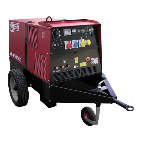
- Page 3 DESCRIPTION OF THE MACHINE TS 400 PS TS 500 PS REV.2-10/13 The TS 400/500 engine driven welder ia a unit which ensures the function as: a) a current source for arc welding b) a current source for the auxiliary power generation It is meant for industrial and professional use, powered by an endothermic engine;...
- Page 4 · Competent support in the solution of problems; ofthe International Certification Network IQNet, · Information and training in the correct applicatio- awarded the official approval to MOSA after an- nand use of the products to assure the security examination of its operations at the head office ofthe operator and protect the environment;...
- Page 5 INDEX TS 400 PS TS 500 PS REV.1-10/13 M 01 QUALITY SYSTEM M 1.01 COPYRIGHT M 1.1 NOTES M 1.4 CE MARK M 1.4.1 DECLARATION OF CONFORMITY M 1.5 TECHNICAL DATA M 1.6 TECHNICAL DATA SYMBOLS M 2.1 SYMBOLS M 2.5 INSTALLATION AND ADVICE BEFORE USE M 2.6 INSTALLATION AND ADVICE...
- Page 6 (see page M1.1). All rights are reserved to said Company. It is a property logo of MOSA division of B.C.S. S.p.A. All other possible logos contained in the documen- tation are registered by the respective owners.
- Page 7 Notes REV.0-10/02 INFORMATION INFORMATION OF GENERAL TYPE In the envelope given together with the machine and/or Dear Customer, set you will find: the manual for Use Maintenance and We wish to thank you for having bought a high quality set. Spare Parts, the manual for use of the engine and the tools (if included in the equipment), the guarantee (in the Our sections for Technical Service and Spare Parts will...
- Page 8 CE MARK REV.6-10/13 Any of our product is labelled with CE marking attesting its conformity to appliable directives and also the fulfillment of safety requirements of the product itself; the list of these directives is part of the declaration of conformity included in any machine standard equipment. Here below the adopted symbol: CE marking is clearly readable and unerasable and it can be either part of the data-plate.
- Page 9 Konformitätserklärung Dichiarazione conformità Declaration of conformity Declaración de conformidad 1.4.1 Déclaration de conformité Declaração de conformidade REV.2-10/13 BCS S.p.A. Stabilimento di Cusago, 20090 (Mi) - Italia V.le Europa 59 Sede legale: Tel.: +39 02 903521 Via Marradi 1 Fax: +39 02 90390466 20123 Milano - Italia DICHIARAZIONE DI CONFORMITA' Déclaration de Conformité...
- Page 10 TECHNICAL DATA TS 400 PS TS 500 PS REV.3-10/13 Technical data TS 400 PS TS 500 PS A.C. GENERATOR Three-phase generation 16 kVA / 400 V / 23.1 A Single-phase generation 12 kVA / 230 V / 52.2 A Single-phase generation 6 kVA / 110 V / 54.4 A Single-phase generation 5 kVA / 48 V / 104 A...
- Page 11 TECHNICAL DATA TS 400 PS TS 500 PS REV.1-02/09 D.C. WELDING TS 400 PS - 50 Hz TS 500 PS - 60 Hz Welding current electronic 20 - 200 / 20 - 400 A 20 - 200 / 20 - 400 A regulation (on two scales) Service 400 A - 60%, 350 A - 100%...
- Page 12 SYMBOLS AND SAFETY PRECAUTIONS REV.0-11/99 SYMBOLS IN THIS MANUAL SAFETY PRECAUTIONS DANGEROUS The symbols used in this manual are designed to call your attention to important aspects of the operation of the machine as well as potential hazards and dangers This heading warns of an immediate danger for persons for persons and things.
- Page 13 SYMBOLS AND SAFETY PRECAUTIONS REV.2-06/10 SYMBOLS PROHIBITIONS No harm for persons Use only with safety clothing - STOP - Read absolutely and be duly attentive It is compulsory to use the personal protection means given in equip- ment. Use only with safety clothing - Read and pay due attention It is compulsory to use the personal protection means given in equipment.
- Page 14 INSTALLATION AND ADVICE BEFORE USE REV.0-06/00 The installation and the general advice concerning the operations, are finalized to the correct use of the ma- chine, in the place where it is used as generator group and/or welder. Stop engine when fueling Do not touch electric devices if you are barefoot or with wet Do not smoke, avoid flames, sparks or electric tools when fueling.
- Page 15 PRECAUTION (ENGINE DRIVEN WELDER) 2-5- REV.0-03/00 INSTALLATION AND ADVICE BEFORE USE The operator of the welder is responsible for the security of the people who work with the welder and for those in the vicinity. The security measures must satisfy the rules and regulations for engine driven welders. The information given below is in addition to the local security norms.
- Page 16 INSTALLATION AND ADVICE REV.1-06/07 Check that the air gets changed completely and the hot INSTALLATION AND ADVICE BEFORE USE air sent out does not come back inside the set so as to cause a dangerous increase of the temperature. GASOLINE ENGINES Use in open space, air swept or vent exhaust gases, which contain the deathly carbone oxyde, far from the work area.
- Page 17 Installazione Luftzirkulation Installation Instalación TS 400 PS Installation TS 500 PS REV.0-06/08...
- Page 18 Dimensioni Abmessungen Dimensions Dimensiones TS 400 PS 2.7.1 Dimensions TS 500 PS REV.0-04/05 SILENCED 1300 1720 CHECKOIL DAI L Y 32.5 57.5 1000...
- Page 19 UNPACKING REV.1-02/04 NOTE + Be sure that the lifting devices are: correctly mounted, adequate for the weight of the machine with it’s pack- aging, and conforms to local rules and regulations. When receiving the goods make sure that the product has not suffered damage during the transport, that there has not been rough handling or taking away of parts contained inside the packing or in the set.
- Page 20 TRANSPORT AND DISPLACEMENTS COVERED UNITS REV.1-06/10 NOTE Transportation must always take place with the engine off, electrical cables and starting battery disconnected and fuel tank empty. Be sure that the lifting devices are: correctly mounted, adequate for the weight of the machine with it’s packaging, and conform to local rules and regulations.
- Page 21 CTL22 ASSEMBLY REV.2-05/09 ATTENTION The CTL accessory cannot be removed from the machine and used separately (actioned manually or following vehicles) for the transport of loads or anyway for used different from the machine movements. TRAILERS The machines provided for assembling the accessory (slow towing trolley) can be towed up to a maximum speed of 40 Kms/hour on asphalted surfaces.
- Page 22 Avoid accidentally spilling fuel. Clean RECOMMENDED OIL any eventual leaks before starting up MOSA recommends selecting AGIP engine oil. motor. Refer to the label on the motor for the recommended products. Refill the tank with good quality diesel fuel, such as automobile type diesel fuel, for example.
- Page 23 Set-up for operation Water cooled systems REV.1-02/11 GROUNDING CONNECTION COOLING LIQUID ATTENTION The grounding connection to an earthed installation is obligatory for all models equipped with a diffe- Do not remove the radiator tap with the rential switch (circuit breaker). In these groups the motor in operation or still hot, as the generator star point is generally connected to the liquid coolant may spurt out and cause...
- Page 24 STARTING AND STOPPING THE ENGINE TS 400 PS TS 500 PS REV.0-05/05 5. start-up at low temperatures. Check daily The motor will normally start up without problems down to temperatures of -10° C, -15° C. In case of starting difficulty, it is possible to repe- at the starting preheating for a max.
- Page 25 CONTROLS LEGENDE REV.3-04/13 Hydraulic oil level light Exclusion indicating light PTO HI Selection push button 30 l/1' PTO HI Welding socket ( + ) Auxiliary current push button Battery voltmeter Welding socket ( - ) Fuel level light Remote control socket Earth terminal E.A.S. PCB Button indicating light 20 l/1' PTO HI A.C. socket Control unit for generating sets QEA Commutator/switch, serial/parallel Accelerator lever Thermal-magnetic circuit breaker Ground fault interrupter ( 30 mA ) Feed pump Selection push button 20 l/1' PTO HI Engine control unit and economiser 48V D.C. socket Water temperature indicator Engine air filter Ammeter Oil level dipstick Frequency meter Engine oil reservoir cap Frequency rpm regulator 24A Hydraulic oil reservoir cap Voltmeter regulator 24B Water filling cap Fuse Fuel prefilter Stop switch Fuel tank cap Warning light, high temperature Muffler...
- Page 26 Comandi Controls Mandos TS 400 PS Commandes TS 500 PS REV.0-04/05 400T230M110M 400T230M48M VERSION VERSION M C2 F5 M1 59A 48V c.a. 5KVA FUSE FUSE (PL VERSION) NO PL VERSION 9 10 12 23-24...
- Page 27 FRONT PANEL COMPONENTS TS 400 PS TS 500 PS REV.0-05/05 Motor protection - Motor control circuit with au- 9 c.c. welding sockets (+) Connection tomatic shutdown for low oil pressure and high 10 c.c. welding sockets (-) sockets for temperature. 9 c.c.
- Page 28 USE AS WELDER TS 400 PS TS 500 PS REV.0-05/05 WELDING CURRENT REGULATION KNOB This symbol (Norm EN 60974-1 security standards for arc welders) signifies that the Position knob (T) in correspondance of the chosen welder can be used in areas with increased current value, so as to obtain the risk of electrical shock.
- Page 29 USE AS WELDER TS 400 PS 34.1 TS 500 PS REV.0-05/05 REDUCTION SCALE For small electrodes (up to Ø 3.25-130A 100% and 4-200A) it is recommended to use the reduction scale switch (I3) allowing a more accurate regulation of the welding current (lever position at 130 A and/or 200A).
- Page 30 USE AS A GENERATOR TS 400 PS TS 500 PS REV.0-05/05 THERMOPROTECTION It is strictly forbidden to connect the group to the public mains a/o to another source of If you overload the genset the thermoprotection will electric power. automatically switch off.
- Page 31 ACCESSORY USE REMOTE CONTROL TC2 / TC2/50 REV.1-06/05 PUSH AND SCREW TIGHT The remote control device for regulating the welding current is connected to the front panel by means of a multipole connector. To regulate the current from the TC2 / TC2/50, move the switch (7), located above the multipole connector (8), to "ON"...
- Page 32 USE OF THE PROTECTION ENGINE PROTECTION 39.4 ES - EV REV..1-04/03 ENGINE PROTECTION (ES - EV) The devices ES or EV ensure the protection of the engine in case of low oil pressure or engine high temperature. The system consist of electronic card of control High temperature and check, and of an engine stop device: solenoid (ElettroStop), electrovalve (ElettroValvola)
- Page 33 TROUBLE SHOOTING TS 400 PS TS 500 PS REV.0-05/05 Problems Possible cause Solution WELDING P1 No welding current but auxiliary 1) Position of remote control switch 1) Check that it is in OFF position if there is no remote control, on output is OK "0"...
- Page 34 TROUBLE SHOOTING TS 400 PS 40.1 TS 500 PS REV.1-06/08 Problems Possible cause Solution ENGINE P1 The engine does not start or stops 1) Low battery voltage, battery dead 1) Check the warning light “state of the battery”: - Green colour: immediately after startup.
- Page 35 MAINTENANCE REV.1-01/13 WARNING ● Have qualified personnel do maintenance and troubleshooting work. ● Stop the engine before doing any work inside the machine. If for any reason the machine must be operated while working inside, pay at- tention moving parts, hot parts (exhaust manifold and muffler, etc.) electrical parts which may be unprotected when the machine is open.
- Page 36 PERIODICAL MAINTENANCE TS 400 PS 44.1 TS 500 PS REV.0-05/05 A B C D E HOW IT WORKS Check the level of the coolant Check the concentration of the coolant (1) Check the tension and the state of the driving belt Replace the control belt of the alternator Drain the water from the prefilter (if assembled) Replace the cartridge of the fuel filter...
- Page 37 STORAGE REV.0-06/07 In case the machine should not be used for more than 30 days, make sure that the room in which it is stored presents a suitable shelter from heat sources, weather changes or anything which can cause rust, corrosion or damages to the machine.
- Page 38 CUST OFF REV.0-06/07 Have qualified personnel disassemble the In case of necessity for first aid and fire prevention, machine and dispose of the parts, including the see page M2.5. oil, fuel, etc., in a correct manner when it is to be taken out of service.
- Page 39 RECOMMENDED ELECTRODES (In accordance with A.W.S Standard) REV.0-10/03 The information here below are to be intended only as indicative since the above norm is much larger. For further details please see the specific norms and/or the manufacturers of the product to be used in the welding process.
- Page 40 ELECTRICAL SYSTEM LEGENDE REV.10-05/13 A : Alternator E3 : Open circuit voltage switch I6 : Start Local/Remote selector N9 : UP/DOWN button mast B : Wire connection unit F3 : Stop push-button L6 : Choke button O9 : Hydraulic unit solenoid valve C : Capacitor G3 : Ignition coil M6 : Switch CC/CV P9 : Hydraulic unit engine D : G.F.I. H3 : Spark plug N6 : Connector – wire feeder Q9 : Ignitor E : Welding PCB transformer I3 : Range switch O6 : 420V/110V 3-phase transformer...
- Page 42 Schema elettrico Stromlaufplan Electric diagram Esquema eléctrico TS 400 PS 61.1 Schemas electriques TS 500 PS REV.1-09/10...
- Page 43 Schema elettrico Stromlaufplan TS 400 PS Electric diagram Esquema eléctrico TS 500 PS 61.2 Schemas electriques 400T230M110M REV.0-04/05...
- Page 44 Schema elettrico Stromlaufplan TS 400 PS Electric diagram Esquema eléctrico 50 Hz 61.3 Schemas electriques 400T230M48M REV.0-04/05...
- Page 45 Schema elettrico Stromlaufplan TS 400 PS-BC Electric diagram Esquema eléctrico TS 500 PS-BC 61.4 Schemas electriques TS 600 PS-BC REV.0-04/05...
- Page 46 Schema elettrico Stromlaufplan Electric diagram Esquema eléctrico TS 400 PS-PL 61.5 Schemas electriques TS 500 PS-PL REV.0-04/05...
- Page 47 Schema elettrico Stromlaufplan Electric diagram Esquema eléctrico TS 400 PS-BC 61.6 Schemas electriques TS 500 PS-BC REV.0-04/05...
- Page 48 Schema elettrico Stromlaufplan Electric diagram Esquema eléctrico TS 400 PS-PL 61.7 Schemas electriques TS 500 PS-PL REV.0-04/05...
- Page 50 MOSA div. della BCS S.p.A. Stabilimento di Viale Europa, 59 20090 Cusago (MI) Italia Tel. + 39 - 0290352.1 Fax + 39 - 0290390466...
Need help?
Do you have a question about the TS 400 PS-BC and is the answer not in the manual?
Questions and answers