
Related Manuals for Mosa TS 250 KD


Summary of Contents for Mosa TS 250 KD
- Page 1 USE AND MAINTENANCE MANUAL Codice Code 120309003 Codigo Kodezahl TS 250 KD Edizione Edition 03.2014 Edición Ausgabe M A D E I T A L Y...
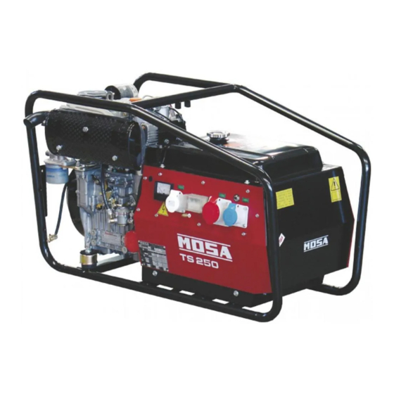
- Page 3 DESCRIPTION OF THE MACHINE TS 250 D REV.0-03/14 The TS 250 engine driven welder ia a unit which ensures the function as: a) a current source for are welding b) a current source for the auxiliary generation Unit meant for industrial and professional use, powered by an endothermic engine; it is composed of various main parts such as: engine, alternator, electric and electronic controls, the fairing or a protective structure.
- Page 5 · Competent support in the solution of problems; ofthe International Certification Network IQNet, · Information and training in the correct applicatio- awarded the official approval to MOSA after an- nand use of the products to assure the security examination of its operations at the head office ofthe operator and protect the environment;...
- Page 6 INDEX REV.2-03/14 M 01 QUALITY SYSTEM M 1.01 COPYRIGHT M 1.1 NOTES M 1.4 CE MARK M 1.4.1 DECLARATION OF CONFORMITY M 1.5 TECHNICAL DATA M 1.6 TECHNICAL DATA ENGINE DRIVEN WELDER M 2-2.1 SYMBOLS AND SAFETY PRECAUTIONS M 2.5... INSTALLATION AND ADVICE BEFORE USE M 2.6 INSTALLATIONS AND ADVICE...
- Page 7 (see page M1.1). All rights are reserved to said Company. It is a property logo of MOSA division of B.C.S. S.p.A. All other possible logos contained in the documen- tation are registered by the respective owners.
-
Page 8: Notes About The Manual
Notes REV.0-10/02 INFORMATION INFORMATION OF GENERAL TYPE In the envelope given together with the machine and/or Dear Customer, set you will find: the manual for Use Maintenance and We wish to thank you for having bought a high quality set. Spare Parts, the manual for use of the engine and the tools (if included in the equipment), the guarantee (in the Our sections for Technical Service and Spare Parts will... - Page 9 CE MARK REV.7-02/14 Any of our product is labelled with CE marking attesting its conformity to appliable directives and also the fulfillment of safety requirements of the product itself; the list of these directives is part of the declaration of conformity included in any machine standard equipment. Here below the adopted symbol: CE marking is clearly readable and unerasable and it can be either part of the data-plate.
-
Page 10: Dichiarazione Di Conformita
Konformitätserklärung Dichiarazione conformità Declaration of conformity Declaración de conformidad 1.4.1 Déclaration de conformité Declaração de conformidade REV.2-10/13 BCS S.p.A. Stabilimento di Cusago, 20090 (Mi) - Italia V.le Europa 59 Sede legale: Tel.: +39 02 903521 Via Marradi 1 Fax: +39 02 90390466 20123 Milano - Italia DICHIARAZIONE DI CONFORMITA' Déclaration de Conformité... - Page 11 Technical data TS 250 D REV.0-03/14 Technical data TS 250 D ALTERNATOR Self-excited, self-regulated, brushless Type three-phase, asynchronous Insulating class GENERATOR Three-phase generation 6.5 kVA / 400 V / 9.4 A Single-phase generation 4.5 kVA / 230 V / 19.5 A Single-phase generation 2 kVA / 48 V / 41.6 A Frequency 50 Hz ENGINE Mark / Model Kohler KD 477/2 Type / Cooling system Diesel 4-Stroke /air Cylinders / Displacement 2 / 954 cm Net output 14.9 kW (20.3 HP)
- Page 12 Technical data TS 250 D REV.0-03/14 WELDING Max DC welding current 200A/60% - 250A/35% Welding current electronic regulation 20 - 250A Open circuit voltage Welding voltage 20-30V EXIT CHARACTERISTICS 100% Welding current regu- lator position approx. current values SIMULTANEOUS UTILIZATION FACTORS In case Welding and Generation can be used simultaneously, however, the engine cannot be overloaded. The table below gives the maximum limits to be respected.
-
Page 13: Symbols In This Manual
SYMBOLS AND SAFETY PRECAUTIONS REV.0-11/99 SYMBOLS IN THIS MANUAL SAFETY PRECAUTIONS DANGEROUS The symbols used in this manual are designed to call your attention to important aspects of the operation of the machine as well as potential hazards and dangers This heading warns of an immediate danger for persons for persons and things. -
Page 14: Symbols And Safety Precautions
SYMBOLS AND SAFETY PRECAUTIONS REV.2-06/10 SYMBOLS PROHIBITIONS No harm for persons Use only with safety clothing - STOP - Read absolutely and be duly attentive It is compulsory to use the personal protection means given in equip- ment. Use only with safety clothing - Read and pay due attention It is compulsory to use the personal protection means given in equipment. - Page 15 INSTALLATION AND ADVICE BEFORE USE REV.0-06/00 The installation and the general advice concerning the operations, are finalized to the correct use of the ma- chine, in the place where it is used as generator group and/or welder. Stop engine when fueling Do not touch electric devices if you are barefoot or with wet Do not smoke, avoid flames, sparks or electric tools when fueling.
- Page 16 PRECAUTION (ENGINE DRIVEN WELDER) 2-5- REV.0-03/00 INSTALLATION AND ADVICE BEFORE USE The operator of the welder is responsible for the security of the people who work with the welder and for those in the vicinity. The security measures must satisfy the rules and regulations for engine driven welders. The information given below is in addition to the local security norms.
-
Page 17: Gasoline Engines
INSTALLATION AND ADVICE REV.1-06/07 Check that the air gets changed completely and the hot INSTALLATION AND ADVICE BEFORE USE air sent out does not come back inside the set so as to cause a dangerous increase of the temperature. GASOLINE ENGINES Use in open space, air swept or vent exhaust gases, which contain the deathly carbone oxyde, far from the work area. - Page 18 Dimensioni Abmessungen Dimensions Dimensiones TS 250 KD 2.7.1 Dimensions REV.0-03/14...
- Page 19 UNPACKING REV.1-02/04 NOTE + Be sure that the lifting devices are: correctly mounted, adequate for the weight of the machine with it’s pack- aging, and conforms to local rules and regulations. When receiving the goods make sure that the product has not suffered damage during the transport, that there has not been rough handling or taking away of parts contained inside the packing or in the set.
- Page 20 TRANSPORT AND DISPLACEMENTS COVERED UNITS REV.2-09/11 NOTE Transportation must always take place with the engine off, electrical cables and starting battery disconnected and fuel tank empty. Be sure that the lifting devices are: correctly mounted, adequate for the weight of the machine with it’s packaging, and conform to local rules and regulations.
-
Page 21: Gasoline Engine
ASSEMBLY CTM222 REV.0-06/00 Note: Lift the machine and assemble the parts as shown in the drawing GASOLINE ENGINE DIESEL ENGINE ATTENTION The CTM accessory cannot be removed from themachine and used separately (actioned ma- nuallyor following vehicles) for the transport of loads oranyway for used different from the machine movements. -
Page 22: Grounding Connection
Set-up for operation (Engine diesel) Air cooled systems REV.1-09/05 OIL BATH AIR FILTER BATTERY WITHOUT MAINTENANCE Connect the cable + (positive) Fill the air filter using the same engine oil up to the to the pole + (positive) of the level indicated on the filter. - Page 23 ENGINE STARTING AND USE (DIESEL ENGINES) REV.0-06/99 ENGINES WITHOUT ACCELERATOR LEVER Check daily lnsert the electric protection device (D-Z2-N2) lever towards above and, where mounted, check the isolation monitor (A3) see page M37 – NOTE Introduce the key (Q1), turn it clockwi- START se completely, leaving it as soon as Do not alter the primary conditions of regulation...
- Page 24 ENGINE STARTING AND USE (DIESEL ENGINES) 21.1 REV.0-06/99 ENGINE WITH PREHEATING GLOW PLUGS Turn the starter key (Q1) on the position "prehea- ting glow plugs" (the glow plugs light will be on I4), when the light is off, turn the starter key completely clockwise until the engine begins to fire.
- Page 25 STOPPING THE ENGINE (DIESEL ENGINE) REV.0-10/00 Before stopping the engine it is compulsory to Remove the key (Q1) turning it counter clockwise, OFF position, then take it out. effect the following operations: START - stop to draw three/single-phase current from the auxiliary sockets.
- Page 26 CONTROLS LEGENDE REV.0-06/07 Hydraulic oil level light Auxiliary current push button Welding socket ( + ) Fuel level light Welding socket ( - ) E.A.S. PCB Earth terminal Control unit for generating sets QEA A.C. socket Ground fault interrupter ( 30 mA ) Accelerator lever Engine control unit and economiser EP1 Feed pump...
- Page 27 Comandi TS 250 KD Controls Mandos Commandes REV.0-03/14...
- Page 28 USE AS WELDER REV.0-06/07 This symbol (Norm EN 60974-1 security MACHINES WITH E.V. PROTECTION standards for arc welders ) signifies that Accelerate the engine at max. with the accelerator the welder can be used in areas with lever (16).See page M 39. increased risk of electrical shock.
- Page 29 USE AS WELDER 34.1 REV.0-06/07 MACHINE WITH REDUCTION SCALE "CC/CV" MODELS SWITCH These models can be used with For small electrodes (up to Ø 3.25-130A 100% electrodes or for TIG welding by selecting and 4-200A) it is recommended to use the the CC (constant current) mode, and with reduction scale switch (I3) allowing a more solid wire (MIG, MAG) or flux cored wire...
-
Page 30: Engine Starter
USE AS AN ENGINE STARTER REV.0-01/01 ENGINE STARTER Keep to the advice indicated page M 21, 26 - Connect the machine with the battery taps (12V or 24V) of the machine engine of which must be started, respecting the polarities (+) et (-). Fally insert the cable plugs into the corresponding sockets (34-34A) turning them clockwise to lock them in position. - Page 31 USE AS A GENERATOR REV.0-06/99 ☞ ☞ It is strictly forbidden to connect the group N.B.: if the warning light does not flash, check to the public mains a/o to another source of the accelerator which must bebat its electric power. maximum, or the fuse of the relevant socket (single-phase) or the thermopro- WARNING...
- Page 32 USE AS A GENERATOR 37.1 REV.0-06/99 TS ... PL VERSION UNIT FITTED WITH GFI SWITCH THERMAL Start the machine and wait for the end of the MAGNETIC BREAKER preheating time imposed by the EP1, EP2, EP5 engine protection device. - See pages M39... - Press the „generation possibility“...
-
Page 33: Accessory Use
ACCESSORY USE REMOTE CONTROL TC2 / TC2/50 REV.0-06/07 PUSH AND SCREW TIGHT The remote control device for regulating the welding current is connected to the front panel by means of a multipole connector. To regulate the current from the TC2 / TC2/50, move the switch (7), located above the multipole connector (8), to "ON"... -
Page 34: Troubleshooting
TROUBLE SHOOTING 40.1 REV.0-06/07 PROBLEM POSSIBLE CAUSE WHAT TO DO No welding current but 1) Defective diode bridge 1) Check the diodes of the bridge auxiliary output is OK 2) Problem with welding current control 2) Is the remote control switch in the (PCB) internal position? 3) Check the diodes and SCR’s of the... - Page 35 MAINTENANCE REV.0-06/10 WARNING ●Have qualified personnel do maintenance and troubleshooting work. ●Stop the engine before doing any work inside the machine. If for any re- ason the machine must be operated while working inside, pay attention moving parts, hot parts (exhaust manifold and muffler, etc.) electrical parts which may be unprotected when the machine is open.
- Page 36 STORAGE REV.0-06/07 In case the machine should not be used for more than 30 days, make sure that the room in which it is stored presents a suitable shelter from heat sources, weather changes or anything which can cause rust, corrosion or damages to the machine.
- Page 37 CUST OFF REV.0-06/07 Have qualified personnel disassemble the In case of necessity for first aid and fire prevention, machine and dispose of the parts, including the see page M2.5. oil, fuel, etc., in a correct manner when it is to be taken out of service.
- Page 38 RECOMMENDED ELECTRODES (In accordance with A.W.S Standard) REV.0-10/03 The information here below are to be intended only as indicative since the above norm is much larger. For further details please see the specific norms and/or the manufacturers of the product to be used in the welding process.
- Page 39 ELECTRICAL SYSTEM LEGENDE REV.10-05/13 A : Alternator E3 : Open circuit voltage switch I6 : Start Local/Remote selector N9 : UP/DOWN button mast B : Wire connection unit F3 : Stop push-button L6 : Choke button O9 : Hydraulic unit solenoid valve C : Capacitor G3 : Ignition coil M6 : Switch CC/CV P9 : Hydraulic unit engine D : G.F.I. H3 : Spark plug N6 : Connector – wire feeder Q9 : Ignitor E : Welding PCB transformer I3 : Range switch O6 : 420V/110V 3-phase transformer...
- Page 40 Stromlaufplan Schema elettrico Electric diagram Esquema eléctrico TS 250 KD 61.1 Schemas electriques REV.0-03/14...
- Page 41 Stromlaufplan Schema elettrico Electric diagram Esquema eléctrico TS 250 KD 61.2 Schemas electriques REV.0-03/14...
- Page 42 Stromlaufplan Schema elettrico Electric diagram Esquema eléctrico TS 250 KD 61.3 Schemas electriques REV.0-03/14...
- Page 43 Ricambi Ersatzteile Spare parts Tabla de recambios TS 250 KD 61.4 Piéces de rechange REV.0-03/14...
- Page 46 WWW.MOSA.IT MOSA div. della BCS S.p.A. Stabilimento di Viale Europa, 59 20090 Cusago (MI) Italia Tel. + 39 - 0290352.1 Fax + 39 - 0290390466...
Need help?
Do you have a question about the TS 250 KD and is the answer not in the manual?
Questions and answers