
Related Manuals for Mosa MAGIC WELD 150


Summary of Contents for Mosa MAGIC WELD 150
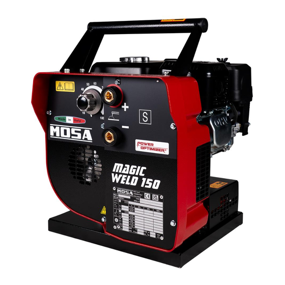
- Page 1 MC0CN50509003_EN 06-2023 Use and Maintenance Manual D5262740 Engine driven welder MAGIC WELD 150 Original instructions...
-
Page 3: Table Of Contents
Precautions during welding ......................17 2.11.1 Precautions in the workplace ....................17 2.11.2 Welding precautions ......................17 2.12 Maintenance precautions .........................19 2.13 Precautions for disposal of waste material ..................20 2.14 Disposal of the machine ........................20 Technical data ..........................21 Dimensions ............................21 MAGIC WELD 150 technical data ....................23... - Page 4 Contents Description ............................25 Main components ..........................25 Control panel components ........................26 Delivery and unpacking .........................27 Delivery .............................27 Unpacking ............................27 Operation ............................29 Grounding ............................29 Checks before start-up ........................29 Starting and stopping the engine ......................30 6.3.1 Starting the engine ......................30 6.3.2 Stopping the engine ......................31 Operation ............................32 6.4.1 Welding cables connection ....................32...
-
Page 5: Introduction
If the manual is lost, damaged or becomes illegible, request a copy to MOSA, indicating the model of the engine driven welder, the serial number and the year of construction. -
Page 6: Customer Service
1. Introduction Customer service The Technical Assistance and Spare Parts Service are available to the Customers. MOSA recommends that you contact the nearest authorised service centre for specialised intervention for all control and overhaul operations. In order to obtain quick and effective responses, indicate the Model and Serial Number shown on the identifi- cation plate (see “1.8 Identification data”). -
Page 7: Identification Data
1. Introduction Identification data The data identifying the machine are given on the EC plate applied in the area indicated in the figure. They are necessary for spare parts requests and communications with the Customer Service Department. D5262750 A - Manufacturer 's data Machine data (1) Country and year of manufacture (2) Model (3) Serial number (4) Technical standard reference Welding data (1) Welding process (2) Symbol for engine driven welders that can be used in environments with a higher risk of electric shock... - Page 8 1. Introduction (5) Duty cycle values (6) Rated welding current values (7) Welding voltage values (8) Rated no-load welding voltage or adjustment range between minimum and maximum value (9) Reduced rated no-load welding voltage with a voltage reduction device (VRD) D - General data (1) Insulation class Engine and machine data...
-
Page 9: Safety
2. Safety Safety Safety information Always respect the warnings contained in this manual and present on the decal applied to the machine. This allows the machine to be used safely, avoiding damage to property and injury or death to people. The following words and symbols were used to identify important safety messages. -
Page 10: Positioning Of Safety Decal And Information
2. Safety Positioning of safety decal and information Machine equipped with HONDA engine D5262770 Machine equipped with MOSA engine D5262780... -
Page 11: Decal Explanation
Use the machine in outdoor and ventilated places. D5260950 • Pos. 4 - Fire, explosion, hot parts and exhaust gas Machine equipped with MOSA engine inhalation hazards Fuel is highly flammable. Turn the engine off and allow it to cool before fuelling. Engine carbon monoxide emissions are highly toxic and poisonous. - Page 12 Pos. 7 - Safety marking Indicates that the engine driven welder may used in environments with a higher risk of electric shock. D5260960 • Pos. 8 - Power Optimizer Function patented by MOSA that prevents engine overload during welding operations. D5260970...
-
Page 13: General Precautions
2. Safety General precautions Any errors during use, checks or maintenance could cause the risk of injury, even serious • Before performing the operations, read this manual and the decals applied to the machine and follow the warn- ings. If you don't understand any part of the manual, ask your Safety Officer for explanations. -
Page 14: Fire Prevention
2. Safety Fire prevention 2.4.1 Fire due to fuel, oil • Avoid approaching any flame to flammable substances such as fuel and oil. • Do not smoke or use open flames near flammable sub- stances. • Stop the machine before refuelling. • Make sure not to spill flammable substances on over- heated surfaces or on parts of the electrical system. • After refuelling, remove any spills and tighten all filling caps tightly. D5260090 •... -
Page 15: Lifting And Transport Precautions
2. Safety Lifting and transport precautions 2.5.1 Lifting by chains or ropes • Make sure that the handling area is clear of obstacles and people. • Handle the machine with the engine off, the electrical cables disconnected and the fuel tank empty. • Lift the machine only by the lifting handle or the frame of the handling carriage. -
Page 16: Transport With Towing Carriage
2. Safety 2.5.3 Transport with towing carriage • On request, the machine can be equipped with an op- tional trolley that facilitates handling. • Handle the machine with the engine off, the electrical cables disconnected and the fuel tank empty. D5262960... -
Page 17: Precautions For Positioning The Machine
2. Safety Precautions for positioning the machine 2.6.1 Positioning site precautions • This machine has been designed for outdoor use and can therefore be positioned outdoors. In case of meteorological precipitation (rain, snow, etc.), place the machine in an adequately sheltered place. -
Page 18: Precautions During Operation
2. Safety Precautions during operation • Keep all panels closed during normal operation. • Access to the internal parts of the machine must only be carried out for maintenance purposes. • Keep the area near the muffler free from objects such as rags, paper, cartons. The high temperature of the muffler could cause the objects to burn and cause a fire. • Do not place objects or obstacles near the air suction and expulsion windows;... -
Page 19: Electromagnetic Compatibility (Emc)
2. Safety 2.10 Electromagnetic Compatibility (EMC) The machine is compliant with European Directive 2014/30/EU on electromagnetic compatibility, and with harmonized standard: EN 60974-10 Electromagnetic Compatibility (EMC) Product Standard for Arc Welding Equipment. All electrical equipment generates small amounts of electromagnetic emission. Electrical emission may be transmitted through power lines or radiated through space, similar to a radio transmitter. -
Page 20: Emission-Reducing Methods
2. Safety ◦ Equipment used for calibration or measurement. • Check that the other equipment in the environment is immune against electromagnetic disturbances. Ensure that the other equipment being used in the environment is compatible. This may require additional protection measures. •... -
Page 21: Precautions During Welding
2. Safety 2.11 Precautions during welding • Access to the internal parts of the machine must only be carried out for maintenance purposes. • Immediately stop the machine in case of malfunctions. Do not restart the machine without first identifying and solving the problem. 2.11.1 Precautions in the workplace • Do not use the welding equipment near heat sources, in areas at risk with explosion hazard or fire haz- ard. - Page 22 2. Safety • Welding generates large amounts of heat. Welded surfaces and materials can cause serious burns. Use gloves and pliers when touching or moving materials in the work area. D5260210 • Welding generates fumes and gases that are hazardous to health. Use sufficient ventilation or a fume extractor to keep fumes and gases away from the breathing area.
-
Page 23: Maintenance Precautions
2. Safety 2.12 Maintenance precautions • Stop the machine and turn the engine switch and fuel valve to OFF. • To avoid injury, do not perform maintenance with the engine running. ◦ Rotating parts, such as the fan, are dangerous and can get entangled on body parts or a worn object. -
Page 24: Precautions For Disposal Of Waste Material
2. Safety 2.13 Precautions for disposal of waste material • Be sure to store the waste liquid in containers or tanks. • Do not discharge the oil directly into the soil or sewage system, rivers, seas or lakes. • When disposing of harmful waste such as oil, fuel, cool- ant, solvents, filters and batteries, follow current laws and regulations. -
Page 25: Technical Data
3. Technical data Technical data Dimensions Machine equipped with HONDA engine 376 mm 435,1 mm 361 mm D5262830 Machine equipped with MOSA engine 369 mm 428,5 mm 361 mm D5262840... - Page 26 3. Technical data Handling carriage 854 mm 610 mm 510 mm 402 mm D5262990...
-
Page 27: Magic Weld 150 Technical Data
3. Technical data MAGIC WELD 150 technical data Machine equipped with HONDA engine Welding Welding Process SMAW (Stick - Coated Electrode) - DC Direct Cur- rent Welding current range 20A / 20.8V - 150A / 20V IEC - Rating 20A / 20.8V - 130A / 25.2V Duty Cycle 80A / 23.2V @100%... - Page 28 3. Technical data Machine equipped with MOSA engine Welding Welding Process SMAW (Stick - Coated Electrode) - DC Direct Cur- rent Welding current range 20A / 20.8V - 150A / 20V IEC - Rating 20A / 20.8V - 140A / 25.4V...
-
Page 29: Description
4. Description Description The engine driven welder is a machine that transforms the mechanical energy generated by a engine into a source of electrical energy suitable for arc welding processes. Main components D5262850... -
Page 30: Control Panel Components
4. Description Transport (or handling) handle Exhaust silencer 3 - Engine air filter Engine exhaust gas outlet Welding level reactor Alternator air ejection grid Chopper bridge Alternator air intake grid Control panel 10 - Alternator 11 - Hall sensor 12 - Welding current control board 13 - Fuel tank cap 14 -... -
Page 31: Delivery And Unpacking
If this occurs, immediately inform the transport company and write down the "Conditional Acceptance” clause in the delivery note. • In the event that, at the time of delivery, significant damage is found, caused during transport, together with any missing parts that may be found, promptly notify MOSA Div. of BCS S.p.A. Unpacking • Unloading of the packaging must be carried out with the utmost care, using lifting equipment of a suitable capaci- ty (e.g. - Page 32 5. Delivery and unpacking 2 - Check the machine identification plate, the integrity of the decal and data, and read the use and maintenance manual before proceeding with use. D5262880...
-
Page 33: Operation
6. Operation Operation WARNING • Before positioning and starting the machine, read section “2. Safety” carefully. Grounding WARNING • Do not connect the machine to a grounding system. • The machine has only welding functions. There is no type of auxiliary generation output to power electrical equipment, such as: grinding wheels, drills, lights, etc. • The machine MUST NOT BE connected to a grounding system and does not have a PE grounding termi- nal. -
Page 34: Starting And Stopping The Engine
6. Operation Starting and stopping the engine WARNING • Do not alter the primary adjustment conditions and do not tamper with sealed parts. 6.3.1 Starting the engine 1 - Turn the fuel valve (1) to the ON position. D5261030 2 - Turn choke control (2) to the closed position (C). WARNING •... -
Page 35: Stopping The Engine
6. Operation 6.3.2 Stopping the engine WARNING • Before stopping the engine, stop the welding process. • In case of emergency, turn the engine switch (3) to the OFF position. 1 - Wait for the engine to decrease the rotations to the minimum speed (about 6-7 seconds after ending the welding work), then wait a few minutes for it to cool down. -
Page 36: Operation
6. Operation Operation This symbol (standard EN 60974-1 – safety requirements for arc welding equipment) indicates that the engine driv- en welder is designed to be used in environments with an increased risk of electric shock. • To reduce the risk of electromagnetic interference, use the minimum length of welding cables and keep them close and low (e.g. on the floor). -
Page 37: Duty Cycle
6. Operation 6.4.3 Duty cycle CAUTION • If the declared time or current values of the duty cycle are exceeded, the engine driven welder could be irreparably damaged. The duty cycle is the percentage of time for which it is possible to weld, at the declared welding current, in a 10 minute period. - Page 38 6. Operation Resistance should be measured between terminals (1) and (3) of the two trimmers R13 and R76. Terminal (2) should not be considered. Example of R13 set-up 1,8 k (1)(+) (–) (–) D5262980...
-
Page 39: Maintenance
7. Maintenance Maintenance WARNING • Before proceeding with maintenance, carefully read section “2. Safety”. • For engine maintenance, refer to the engine maintenance manual. Refuelling • Use fuel and lubricants according to the ambient temperature. 7.1.1 Fuel • Only use gasoline and fill the tank with clean fuel. • Keep the engine off during refuelling. -
Page 40: Clean Air Filter
7. Maintenance 2 - Insert the cap into the filler neck without screwing it in, and remove it again to check the oil level on the dipstick (2). D5261140 3 - If the oil level is near or below the lower limit mark (Min.), Min. fill the oil to the upper limit mark (Max.) (lower edge of the filler hole). D5261150 Clean air filter 7.2.1 Inspection 1 - Remove the air filter cover and inspect the filter elements. -
Page 41: Storage
7. Maintenance Storage • Carefully clean the fairings and all other machine parts. • If the machine is not used for more than 30 days, make sure that the machine is protected from heat sources and from weather phenomena that can cause rust, corrosion of the components and damage to the machine. - Page 42 7. Maintenance NOTES:...
-
Page 43: Troubleshooting
8. Troubleshooting Troubleshooting Engine Issue Possible cause Solution The engine will not start, or starts 1) Engine switch (28) in the OFF posi- 1) Set the switch to ON. and stops immediately. tion. 2) No or insufficient oil in the engine. 2) Refill or top up. 3) Faulty engine stop device (oil-alert). 4) No fuel in tank or fuel valve closed. 3) Replace. 5) Faulty or dirty spark plug. 4) Fill the tank. - Page 44 2) Auto Idle - Economizer system failure 2) Check the resistance of the solenoid winding, it must be about 10 Ohms. Replace. Request the intervention of the Support Service. Table (1) Magic Weld 150 Winding resistors at 20 °C Outputs mΩ Welding 22.0...
- Page 46 MOSA div. della BCS S.p.A. Viale Europa, 59 20047 Cusago (Milano) Italy Tel.+39 - 0290352.1 Fax +39 - 0290390466 www.mosa.it...
Need help?
Do you have a question about the MAGIC WELD 150 and is the answer not in the manual?
Questions and answers