Atlona AT-HD-SC-500 Manual
Three-input hd video scaler
Hide thumbs
Also See for AT-HD-SC-500:
- User manual (27 pages) ,
- Quick start manual (7 pages) ,
- Manual (22 pages)
Table of Contents
Advertisement
Quick Links
Download this manual
See also:
User Manual
Advertisement
Table of Contents

Subscribe to Our Youtube Channel
Related Manuals for Atlona AT-HD-SC-500


Summary of Contents for Atlona AT-HD-SC-500
- Page 1 Three-Input HD Video Scaler for HDMI and VGA Signals Atlona Manuals AT-HD-SC-500 Switchers...
- Page 2 Version Information Version Release Date Notes 04/17 New manual format 05/17 Added DispBtn command (only available when running firmware v1.3.30) AT-HD-SC-500...
- Page 3 Welcome to Atlona! Thank you for purchasing this Atlona product. We hope you enjoy it and will take a extra few moments to register your new purchase. Registration only takes a few minutes and protects this product against theft or loss. In addition, you will receive notifications of product updates and firmware.
- Page 4 Atlona requires that products returned are properly packed, preferably in the original carton, for shipping. Cartons not bearing a return authorization or case number will be refused. Atlona, at its sole discretion, reserves the right to reject any products received without advanced authorization. Authorizations can be requested by calling 1-877-536-3976 (US toll free) or 1-408- 962-0515 (US/international) or via Atlona’s website at www.atlona.com.
- Page 5 Damage, deterioration or malfunction resulting from the installation or removal of this product from any installation, any unauthorized tampering with this product, any repairs attempted by anyone unauthorized by Atlona to make such repairs, or any other cause which does not relate directly to a defect in materials and/or workmanship of this product.
-
Page 6: Important Safety Information
Where shielded interface cables have been provided with the product or specified additional components or accessories elsewhere defined to be used with the installation of the product, they must be used in order to ensure compliance with FCC regulations. AT-HD-SC-500... -
Page 7: Table Of Contents
Introduction to the Web GUI Logging In Menus Toggles Sliders Buttons Getting Information on the Switcher Video Menu Input Output Audio Menu Picture Menu EDID Menu Display Menu System Settings TCP/IP Settings of Controlled Devices RS-232 / IP Commands RS-232 Menu AT-HD-SC-500... - Page 8 Table of Contents OSD Menu Config Menu Network Menu Commands Appendix Updating the Firmware Using the Web GUI Using USB Mounting Instructions Default Settings Specifications Index AT-HD-SC-500...
-
Page 9: Introduction
• Firmware upgradable for easy field service through USB or web GUI Package Contents 1 x AT-HD-SC-500 1 x Phoenix terminal block, 5-pin (captive screw) 1 x Phoenix terminal block, 3-pin (captive screw) 1 x Phoenix terminal block, 2-pin (captive screw) -
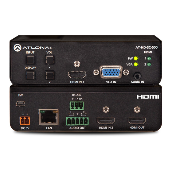
Page 10: Panel Description
Panel Description AT-HD-SC-500 INPUT HDMI DISPLAY Front Rear HDMI IN 1 VGA IN AUDIO IN AT-HD-SC-500 RS-232 INPUT HDMI DISPLAY HDMI IN 1 VGA IN AUDIO IN HDMI OUT AUDIO OUT HDMI IN 2 DC 5V RS-232 9 11 INPUT... -
Page 11: Installation
Installation RS-232 The AT-HD-SC-500 provides RS-232 control between an automation system and an RS-232 device. This step is optional. 1. Use wire strippers to remove a portion of the cable jacket. 2. Remove at least 3/16” (5 mm) from the insulation of the RX, TX, and GND wires. -
Page 12: Audio
Installation Audio The AUDIO OUT connector on the AT-HD-SC-500 provides the connection of either balanced or unbalanced audio outputs using XLR connectors. Use the included 5-pin Phoenix terminal block. Balanced audio connections use two signal wires and a ground to minimize interference in audio signals. Unbalanced audio connections use one signal wire and a ground and are used if system components don’t support balanced... -
Page 13: Connection Diagram
ID G 3 .5 ST ER M IC LI N r ic R SY IN P AT-PA100-G2 Speakers Projector AT-HD-SC-500 C -5 D -S A T -H D IO A IN IN P P L A D IS Laptop Laptop... -
Page 14: Ip Configuration
IP Configuration The AT-HD-SC-500 is shipped with DHCP enabled. Once connected to a network, the DHCP server (if available), will automatically assign an IP address to the unit. Use an IP scanner, along with the MAC address on the bottom of the unit, to identify both the unit and its IP address on the network. -
Page 15: Using The Web Gui
GUI, allows the AT-HD-SC-500 to use either DHCP or static IP mode. In order to access the web GUI, the IP address of the AT-HD-SC-500 must be known. 1. Open the desired web browser and enter the IP address of the AT-HD-SC-500. -
Page 16: Basic Operation
Adjusting the Output Volume Press the VOL UP / DN buttons on the front panel of the AT-HD-SC-500 to control the output volume of the display device. Output volume is displayed in decibels, and can be set from -32 dB to 0 dB. -
Page 17: Auto Switching
Passing Analog Audio The AT-HD-SC-500 can pass two-channel analog audio, by itself, or with a VGA signal. The signal is embedded on the HDMI output. 1. Connect a 3.5 mm mini-stereo cable from the AUDIO IN port to the analog audio source. - Page 18 The example, below, shows a desktop PC providing both the audio and video source. However, these signals may be connected to separate sources. The dotted line indicates that the video source is optional. AT-HD-SC-500 - 5 0 - S C...
-
Page 19: Menu System
Menu System Accessing the On-Screen Display The AT-HD-SC-500 includes a built-in On-Screen Display (OSD) menu system to manage and control all video features. 1. Press and hold the DISPLAY button, until the OSD is shown. AT-HD-SC-500 INPUT HDMI Main Menu... -
Page 20: Input Select
1280x800 1366x768 1680x1050 1920x1080 1920x1200 Menu Back 6. Press the VOL UP/DN buttons to select the desired resolution. 7. Press the DISPLAY button to confirm the selection. 8. Press the Menu Back option to return to the Main Menu. AT-HD-SC-500... -
Page 21: Output Resolution
4. Press the VOL UP/DN buttons to highlight the desired option. Picture Adjust Brightness Contrast Saturation Sharpness Picture Reset ColorSpace Menu Back 5. Press the DISPLAY button to confirm the selection. 6. The current value will be highlighted in green and surrounded by brackets and two arrowheads. AT-HD-SC-500... -
Page 22: Aspect
Keep Ratio The input aspect ratio is preserved on the output. 5. Press the DISPLAY button to confirm the selection. 6. Select the Menu Back option, then press the DISPLAY button, to return to the Main Menu. AT-HD-SC-500... -
Page 23: Overscan
HDMI2 EBD. Aud Auto Menu Back 4. Press the VOL UP/DN buttons to highlight the desired option. 5. Press the DISPLAY button to confirm the selection. 6. The current value will be highlighted in green and surrounded by brackets and two arrowheads. AT-HD-SC-500... - Page 24 7. Press the VOL UP/DN buttons to select the desired value. Press the VOL UP button to increase the value; press VOL DN to decrease the value. 8. Press the DISPLAY button to confirm the value. 9. Highlight the Menu Back option, then press the DISPLAY button to return to the Main Menu. AT-HD-SC-500...
-
Page 25: Osd
Off - Prevents the Info Display screen from being displayed. • On - The Info Display screen is always displayed. Background Sets the background color of the OSD. The following options are available: • Grey • Cyan • Magenta • Yellow AT-HD-SC-500... -
Page 26: Control Settings
Enables or disables Consumer Electronics Control (CEC) command transmission to the display (sink) device. • On - Allows CEC commands to be transmitted over the HDMI cable to the connected display (sink) device. • Off - Prevents transmission of CEC commands. AT-HD-SC-500... - Page 27 Sets the feedback verification state. The following options are available: • On - The AT-HD-SC-500 will make four attempts to send the command. If the feedback string is not acknowledged after the fourth attempt, the process will fail. Execute the...
-
Page 28: Others
NOTE: Some source devices will enable HDCP if an HDCP- compliant display (sink) is detected. However, there may be applications where sending HDCP content is not desired. This feature does not provide decryption of HDCP content to non-HDCP sink devices AT-HD-SC-500... -
Page 29: Information
9. Highlight the Menu Back option, then press the DISPLAY button to return to the Main Menu. Information The Information displays current information about the AT-HD-SC-500. None of the fields within the Information menu can be edited. 1. Under the Main Menu, highlight the Information menu item using the VOL UP/DN buttons on the front panel. - Page 30 Displays any detailed (alternate) timing for the display. IP Address IP address of the display. F W Version Current version of firmware running on the switcher. 4. The Menu Back option will already be selected. 5. Press the DISPLAY button to return to the Main Menu. AT-HD-SC-500...
-
Page 31: Web Gui
Web GUI Introduction to the Web GUI The AT-HD-SC-500 includes a built-in web GUI. Atlona recommends that the web GUI be used to control the AT-HD-SC-500, as it provides intuitive management of all features. The AT-HD-SC-500 is shipped with DHCP enabled. Once connected to a network, the DHCP server will automatically assign an IP address to the unit. -
Page 32: Menus
Once the desired menu element is highlighted, click the left mouse button to access the settings within the menu. Menu bar In this example, clicking Audio, in the menu bar, will display the Audio page. AT-HD-SC-500... -
Page 33: Toggles
Overscan setting, must be set to the ON position in order for the slider controls to be adjusted. In some cases, the toggle will allow switching between two settings, such as the IP Mode setting, under the Network menu. This toggle sets the AT-HD-SC-500 to either static or DHCP mode. Refer to Network Menu (page for more information on this feature. -
Page 34: Buttons
The model name of this switcher. Software Version The version of firmware that the AT-HD-SC-500 is running. Always make sure to check the AT-HD-SC-500 product page, on the Atlona web site, for the latest version of firmware. Input Port The active input port on the switcher. -
Page 35: Video Menu
• Click the Fallback Time (Sec) drop-down list and select the time interval before the switcher attempts to search for the next port. Range: 3 to 600. AT-HD-SC-500... -
Page 36: Output
Click the Mirror-V toggle to the ON setting. Enabling this feature applies a vertical transformation (rotated 180° about the x-axis) to the output signal. ASP Background Click this drop-down list to select the color of the bars that appear when viewing an image in “letterbox” format. AT-HD-SC-500... -
Page 37: Audio Menu
Output Bass Click and drag this slider bar to adjust the bass of the audio output. Range: -15 to 15. Output Treble Click and drag this slider bar to adjust the treble of the audio output. Range: -15 to 15. AT-HD-SC-500... -
Page 38: Picture Menu
Adjusts the hue of the output signal. Range: 0 - 128 Sharpness Adjusts the sharpness of the output signal. Range: 0 - 128 Reset all Picture Click this button to reset the above picture settings to their factory-default settings. AT-HD-SC-500... -
Page 39: Edid Menu
Auto - Automatically detects the presence of HDCP-compliant sink devices. If an HDCP-compliant display is detected, then HDCP content will be sent. Otherwise, non-HDCP content will be sent. NOTE: The HDCP control feature does not provide decryption of HDCP content to non-HDCP sink devices. AT-HD-SC-500... -
Page 40: Display Menu
Web GUI Display Menu CEC Command Click the ON button to send the power-on command to the display device. Click the OFF button to toggle the power state to off. AT-HD-SC-500... -
Page 41: System Settings
Sets the feedback verification state. Click the toggle to enable or disable this feature. The following options are available. Setting Description The AT-HD-SC-500 will make four attempt to send the command, if the feedback string is not acknowledged. After the fourth attempt, the process will fail. Execute the SetCmdFB (page 72) command to set the feedback string. -
Page 42: Tcp/Ip Settings Of Controlled Devices
Requires a username and password to control the display through TCP/IP. IP Address Enter the IP address of the display in this field. Port Enter the listening port of the device in this field. Username Enter the username for login. Password Enter the password for login. AT-HD-SC-500... -
Page 43: Rs-232 / Ip Commands
Click this drop-down list to select the desired end-of-line characters to be sent. Setting Description None No end-of-line characters included Carriage return Line feed CR-LF Carriage return + Line feed Space Space character Start-of-text character End-of-text character Null Null character (binary zero) AT-HD-SC-500... -
Page 44: Rs-232 Menu
Web GUI RS-232 Menu Baud rate Sets the baud rate for the AT-HD-SC-500. The following options are available: 2400, 4800, 9600, 19200, 28800, 57600, 115200. Data bit Sets the number of data bits used to represent each character of data. The following options are available: 5, 6, 7, 8, 9. -
Page 45: Osd Menu
The screen will automatically be hidden after approximately five seconds. Prevents the Info Display screen from being displayed. The Info Display screen is always displayed. Background Sets the background color of the OSD. The following options are available: Grey, Cyan, Magenta, Yellow. AT-HD-SC-500... -
Page 46: Config Menu
Config Menu Old Username This field cannot be changed. “root” is the administrator user. Old Password Enter the current password for the “root” username in this field. The default password is “Atlona”. New Username This field cannot be changed. Save Click this button to save all changes. -
Page 47: Network Menu
Click this toggle to set the IP mode of the AT-HD-SC-500. By default, the AT-HD-SC-500 is set to DHCP mode. Enter the IP address of the AT-HD-SC-500 in this field. This field will only be available if IP Mode is set to STATIC IP. - Page 48 Web GUI Save Click this button to save all changes to the network settings. Update Click this button to begin the upgrade procedure. Refer to Updating the Firmware (page 81) for more information. AT-HD-SC-500...
-
Page 49: Commands
Commands The following tables provide an alphabetical list of commands available on the AT-HD-SC-500. All commands are case-sensitive and must be entered as documented. Command Description AnaGain Sets the gain of the analog audio input ASPBGRND Sets the matte color for the bars used in viewing letterbox formats... - Page 50 Sets the Telnet listening port for the AT-HD-SC-500 IPQuit Terminates the Telnet session IPStatic Sets the static IP address, subnet mask, and gateway for the AT-HD-SC-500 IPTimeout Specifies the time interval of inactivity before the Telnet session is closed LampCool...
- Page 51 Unlock Unlocks the buttons on the front panel Scrolls up the cursor, in the OSD menu, one position Version Displays the current firmware version of the At-HD-SC-500 VGAAuto Automatically adjusts the clock and phase of the VGA signal VidOutRes Sets the video output resolution...
- Page 52 Sets the aspect ratio of the output signal. The default setting is Full. Syntax Aspect X Parameter Description Range Aspect ratio 0 = Full 1 = 16:9 2 = 16:10 3 = 4:3 4 = Keep Ratio Example Feedback Aspect 1 Aspect 1 AT-HD-SC-500...
- Page 53 ASwOutTime 15 ASwOutTime 15 ASwPrePort Sets the fallback input when auto-switching is enabled. Use the sta argument to return the current fallback input. To always return the AT-HD-SC-500 to the last active input, use the Prev argument. Syntax ASwPrePort X Parameter...
- Page 54 Description Range Value on, off, sta Example Feedback AutoDispOn on AutoDispOn on AutoPwrMode Sets the display mode for auto-power on and off. Syntax AutoPwrMode X Parameter Description Range Value DISPAVON, DISPAVSW, AVSW, sta Example Feedback AutoPwrMode DISPAVON AutoPwrMode DISPAVON AT-HD-SC-500...
- Page 55 GUI will also be affected on the control system (if connected), via TCP/IP. To separate control between web GUI and Telnet, set this feature off. on = enables broadcast mode; off = disables broadcast mode; sta = displays the current Broadcast setting. Syntax Broadcast X Parameter Description Range Value on, off, sta Example Feedback Broadcast on Broadcast on AT-HD-SC-500...
- Page 56 IP address of the Telnet client. DHCP must be disabled before using this command. Refer to the IPDHCP (page 64) command for more information. Syntax CliIPAddr X Parameter Description Range IP address 0 ... 255 (per byte) Example Feedback CliIPAddr 192.168.1.61 CliIPAddr 192.168.1.61 AT-HD-SC-500...
- Page 57 Example Feedback CliMode login CliMode login CliPass Sets the password for the Telnet client. Execute the CliPass command without arguments to display the current password. The default password is Atlona. Syntax CliPass X Parameter Description Range Password...
- Page 58 Syntax CSpara[W,X,Y,Z] Parameter Description Range Baud rate 2400, 4800, 9600, 19200, 38400, 57600, 115200 Data bits 7, 8 Parity bit None, Odd, Even Stop bits 1, 2 Example Feedback CSpara[115200,8,0,1] CSpara[115200,8,0,1] CSpara[sta] CSpara [115200,8,0,1] AT-HD-SC-500...
- Page 59 Sets the time interval, in seconds, between when the display is powered on and when the DISPLAY button, on the front panel, will be locked. Use the sta argument to display the current time interval. Syntax DisWarmUp X Parameter Description Range Time interval 0 ... 300, sta Example Feedback DisWarmUp 120 DisWarmUp 120 AT-HD-SC-500...
- Page 60 Disabling this feature will not decrypt HDCP content. on = enables HDCP detection; off = disables HDCP detection; sta = displays the current HDCPSet1 setting. Syntax HDCPSet1 X Parameter Description Range Value on, off, sta Example Feedback HDCPSet1 on HDCPSet1 on AT-HD-SC-500...
- Page 61 Displays the list of available commands. To obtain help on a specific command, enter the Help command followed by the name of the command. Syntax Help X Parameter Description Range Command name Optional Example Feedback Help Command List ----------------- Help IPCFG CliIPAddr CliPort AT-HD-SC-500...
- Page 62 Enables / disables the OSD info screen. on = info screen always on, off = info screen is off, auto = info screen is displayed when a resolution change is made, then is automatically hidden, sta = displays the current INFOOSD setting. Syntax INFOOSD X Parameter Description Range Value on, off, sta Example Feedback INFOOSD on INFOOSD on AT-HD-SC-500...
- Page 63 GUI. Refer to Config Menu (page 46) for more information. Syntax IPAddUser X Y Parameter Description Range User name 20 characters (max) Password 20 characters (max) Example Feedback IPAddUser BigBoss b055man IPAddUser BigBoss b055man TCP/IP user was added AT-HD-SC-500...
- Page 64 IPDHCP Enables / disables DHCP mode on the AT-HD-SC-500. on = enables DHCP mode; off = disables DHCP mode; sta = displays the current IPDHCP setting. If this feature is disabled, then a static IP address must be specified for the AT-HDR-M2C.
- Page 65 IPLogin Enables / disables the use of login credentials when starting a Telnet session on the AT-HD-SC-500. If this feature is set to on, then the AT-HD-SC-500 will prompt for both the username and password. Use the same credentials as the web GUI.
- Page 66 “power off” command has been processed and the projector lamp has completed the cool-down cycle. Use the sta argument to display the current port setting. Syntax LampCool X Parameter Description Range Interval (in seconds) 0 ... 300, sta Example Feedback LampCool 120 LampCool 120 AT-HD-SC-500...
- Page 67 Sets the time interval before the OSD menu system is automatically hidden after no activity. Use the sta argument to display the current MENUTMR setting. Syntax MENUTMR X Parameter Description Range Interval (in seconds) 5 ... 100, sta Example Feedback MENUTMR 60 MENUTMR 60 AT-HD-SC-500...
- Page 68 Range Value on, off, sta Example Feedback MirrorV on MirrorV on Mreset Resets the AT-HD-SC-500 to factory-default settings. Syntax MReset This command does not require any parameters Example Feedback Mreset Mreset Sets the location of the OSD menu on the screen. 0 = Left-Top, 1 = Right-Top, 2 = Right-Bottom, 3 = Left-Bottom, 4 = Center, sta = displays the current OSD setting.
- Page 69 Sets the background color of the OSD menu. 0 = grey, 1 = cyan, 2 = magenta, 3 = yellow, sta = displays the current OSDBGRND setting. Syntax OSDBGRND X Parameter Description Range Color 0 ... 3, sta Example Feedback OSDBGRND 2 OSDBGRND 2 PicReset Resets all picture settings. Syntax PicReset This command does not require any parameters Example Feedback PicReset PicReset AT-HD-SC-500...
- Page 70 Locks / unlocks the DISPLAY key on the front panel. on = enables DISPLAY lock, off = disables DISPLAY lock button, sta = displays the current PWLock setting. Syntax PWLock Parameter Description Range Value on, off, sta Example Feedback PWLock on PWLock on AT-HD-SC-500...
- Page 71 This command does not require any parameters Example Feedback RAtlMac b8-98-b0-01-21-7c SATRT Sets the picture color saturation value. Use the sta argument to display the current SATRT setting. Syntax SATRT X Parameter Description Range Saturation 0 ... 100, sta Example Feedback SATRT 50 SATRT 50 AT-HD-SC-500...
- Page 72 Command Command string Example Feedback SetCmd mute[Select] SetCmd mute[Select] SetCmdFB Sets the feedback string for the specified command key. Syntax SetCmdFB X Parameter Description Range Feedback string Feedback string Example Feedback SetCmdFB mute[Selected] SetCmdFB mute[Selected] AT-HD-SC-500...
- Page 73 Sets the time period (in seconds) to place the unit in standby. Use the sta argument to display the current SetOff setting. Syntax SetOff X Parameter Description Range Time interval 5 ... 240, sta Example Feedback SetOff 60 SetOff 60 AT-HD-SC-500...
- Page 74 Parameter Description Range Sharpness 0 ... 100, sta Example Feedback SHARP 70 SHARP 70 System Displays system information about the AT-HD-SC-500. The sta argument must be specified. Syntax System X Parameter Description Range Status Example Feedback System sta Model: AT-HD-SC-500...
- Page 75 Example Feedback TrigCEC on TrigCEC on TrigIP Trigger the stored IP commands to the Telnet client. Syntax TrigIP X Parameter Description Range Value on, off, vol+, vol-, mute Example Feedback TrigIP vol+ TrigIP vol+ AT-HD-SC-500...
- Page 76 UARTPara 115200,8,0,1 UARTPara setting ok! Unlock Unlocks the buttons on the front panel. Use the Lock (page 67) command to lock the buttons on the front panel. Syntax Unlock This command does not require any parameters Example Feedback Unlock Unlock AT-HD-SC-500...
- Page 77 1.3.10 VGAAuto Executes the VGA auto-adjust. This command automatically adjusts the phase and clock of the VGA signal. A VGA display must be connected to the AT-HD-SC-500 when executing this command. Otherwise, the command will fail. Syntax VGAAuto This command does not require any parameters...
- Page 78 1 value, respectively. To display the current value, execute the VOUT1 command without any arguments. Syntax VOUT1 Parameter Description Range Value -80 ... 6 Example Feedback VOUT1 4 VOUT1 4 VOUT1 + VOUT1 5 AT-HD-SC-500...
- Page 79 VOUTOSD off VZoom Adjusts the vertical zoom (overscan) of the output image. Use the sta argument to display the current VZoom setting. Syntax VZoom X Parameter Description Range Value 0 ... 50, sta Example Feedback VZoom 10 VZoom 10 AT-HD-SC-500...
- Page 80 Zoom Enables / disables overscan. on = enables overscan; off = disables overscan; sta = displays the current Zoom setting. Syntax Zoom X Parameter Description Range Value on, off, sta Example Feedback Zoom on Zoom off AT-HD-SC-500...
-
Page 81: Appendix
Updating the firmware can be completed using either the USB interface or the web GUI. Atlona recommends using the web GUI for updating the firmware. However, If a network connection is not available, the AT-HD-SC-500 firmware can be updated using a USB-A to USB mini-B cable. -
Page 82: Using Usb
USB-A to USB mini-B cable AT-HD-SC-500 INPUT HDMI 1. Disconnect power from the AT-HD-SC-500. DISPLAY 2. Connect the USB-A to USB mini-B cable from the computer to the FW port on the AT-HD-SC-500. FW port HDMI IN 1 VGA IN AUDIO IN RS-232... - Page 83 7. Delete all files from the USB UPDATE drive, if any are present. 8. Drag-and-drop the HDSC-500-FW-[version].BIN firmware file to the drive. 9. After the file has been copied, disconnect the USB cable from both the computer and the AT-HD-SC-500. 10. Power-cycle the AT-HD-SC-500 by disconnecting then reconnecting the power supply.
-
Page 84: Mounting Instructions
Appendix Mounting Instructions The AT-HD-SC-500 includes two mounting brackets, which can be used to attach the unit to any flat surface. Use the enclosure screws, on the sides of the unit to attach the mounting brackets. 1. Using a small Phillips screwdriver, remove the four screws from the left side of the enclosure. -
Page 85: Default Settings
Appendix Default Settings The following tables list the factory-default settings for the AT-HD-SC-500. Feature Settings Video Input Selection HDMI 1 Auto Switch mode Fallback Port Previous Fallback Time (Sec) Output Resolution 1280x720p60 Color Space Aspect Full Overscan Mirror-V ASP Background... - Page 86 Parity None Stop bit Position Left-Top Transparency Info. Timer Menu Timer Info. Display Auto Background Grey Network IP Mode DHCP assigned by DHCP server Netmask 255.255.255.0 Gateway assigned by DHCP server Telnet Port Telnet Login Mode Telnet Timeout Broadcast AT-HD-SC-500...
-
Page 87: Specifications
Resolution / Distance Feet Meters HDMI IN/OUT @ 1080p Signal Bandwidth 6.75 Gbps HDCP Switchable – Compliant/Non-compliant Temperature Fahrenheit Celsius Operating 32 to 122 0 to 50 Storage -4 to 140 -20 to 60 Humidity (RH) 20% to 90%, non-condensing AT-HD-SC-500... - Page 88 Output: 5 V DC, 3.6 A Dimensions Inches Millimeters H x W x D 1.5 x 5 x 4.02 38 x 127 x 102 Weight Pounds Kilograms Unit 0.60 0.27 Certification Power Supply CE, TUV, RCM, RoHS, FCC Product CE, FCC AT-HD-SC-500...
-
Page 89: Index
VOUT1 Mounting instructions DispBtn VOUTMute1 Muting DisWarmUp 59, 60 VOUTOSD audio 37, 79 Down VZoom HDCPSet1 HDCPSet2 Zoom HDMIAUD Configuration Operating notes Help See IP configuration Connection displaying HZoom diagram settings INFOOSD instructions Output volume INFOTMR Contents adjusting Input package AT-HD-SC-500... - Page 90 Safety information Saturation 21, 38 Sharpness 38, 74 Specifications Static IP 31, 47, 66 Subnet mask Switching auto 17, 35 Telnet listening port login mode timeout Timer auto power-off display warm-up lamp cool down Treble adjusting Users AT-HD-SC-500...
- Page 91 877.536.3976 © 2017 Atlona Inc. All rights reserved. “Atlona” and the Atlona logo are registered trademarks of Atlona Inc. All other brand names and trademarks or registered trademarks are the property of their respective owners. Pricing, specifications and availability subject to change without notice. Actual products, product images, and online product images may vary from images shown here.
Need help?
Do you have a question about the AT-HD-SC-500 and is the answer not in the manual?
Questions and answers