Table of Contents
Advertisement
Quick Links
Module for Stepper
TMCM-1076 Hardware Manual
Hardware Version V1.10 | Document Revision V1.00 • 2018-JUN-25
The TMCM-1076 is an easy to use stepper motor driver module. The module is controlled via a
step and direction interface. One con guration pin selects the current control mode between
stealthChop™ for absolute silent motor control and spreadCycle™ for high speed. A TTL UART
interface allows for more advanced con guration and permanent parameter storage via TMCL™-
IDE.
Applications
• Lab-Automation
• Manufacturing
Simpli ed Block Diagram
TMCL
Memory
9...24V
UART
STEP/DIR
EN
CHOP
©2018 TRINAMIC Motion Control GmbH & Co. KG, Hamburg, Germany
Terms of delivery and rights to technical change reserved.
Download newest version at:
www.trinamic.com
Read entire documentation.
• Robotics
• Factory Automation
SPI
SPI
µC
Features
• Supply Voltage +10. . . +30V DC
• Up to 3A RMS motor current
• Step and direction interface
• microPlyer™ to 256 µ-steps
• stealthChop™ silent PWM mode
• spreadCycle™ smart mixed decay
• stallGuard2™ load detection
• coolStep™ autom. current scaling
• UART con guration interface
• CNC
• Laboratory Automation
cDriver
with
stealthChop
MODULE
Step
Motor
Advertisement
Table of Contents

Related Manuals for Trinamic TMCM-1076


Summary of Contents for Trinamic TMCM-1076
- Page 1 Hardware Version V1.10 | Document Revision V1.00 • 2018-JUN-25 The TMCM-1076 is an easy to use stepper motor driver module. The module is controlled via a step and direction interface. One con guration pin selects the current control mode between stealthChop™...
-
Page 2: Table Of Contents
TMCM-1076 Hardware Manual • Hardware Version V1.10 | Document Revision V1.00 • 2018-JUN-25 2 / 22 Contents 1 Features 1.1 General Features .......... -
Page 3: Features
1 Features The TMCM-1076 is an easy to use stepper driver unit with state of the art feature set. It is highly integrated and offers a convenient handling. TMCM-1076 can be used with a simple step and direction interface and can be con gured using a TTL UART interface. -
Page 4: Trinamic's Unique Features
TMCM-1076 Hardware Manual • Hardware Version V1.10 | Document Revision V1.00 • 2018-JUN-25 4 / 22 1.2 TRINAMIC’s Unique Features 1.2.1 stealthChop™ stealthChop is an extremely quiet mode of operation for low and medium velocities. It is based on a voltage mode PWM. -
Page 5: Stallguard2
TMCM-1076 Hardware Manual • Hardware Version V1.10 | Document Revision V1.00 • 2018-JUN-25 5 / 22 1.3 stallGuard2 stallGuard2 is a high-precision sensorless load measurement using the back EMF of the motor coils. It can be used for stall detection as well as other uses at loads below those which stall the motor. The stallGuard2 measurement value changes linearly over a wide range of load, velocity, and current settings. -
Page 6: Order Codes
TMCM-1076 Hardware Manual • Hardware Version V1.10 | Document Revision V1.00 • 2018-JUN-25 6 / 22 2 Order Codes Order Code Description Size (LxWxH) TMCM-1076 Controller/Driver Module without motor, +24V DC, 3A RMS, 60mm x 60mm x 13mm TTL UART interface (9600bps default), S/D interface, Enable,... -
Page 7: Mechanical And Electrical Interfacing
The dimensions of the TMCM-1076 are approximately 60mm x 60mm x 13mm. There are four mounting holes for M3 screws for mounting the TMCM-1076. These mounting holes are located in the bottom / base plate and accessible after removing the top cover (see 5, right gure, mounting holes marked red). Two of them at opposite positions can be used for mounting the module to the backside of our NEMA23 stepper motors (screw/thread length depends on motor size). -
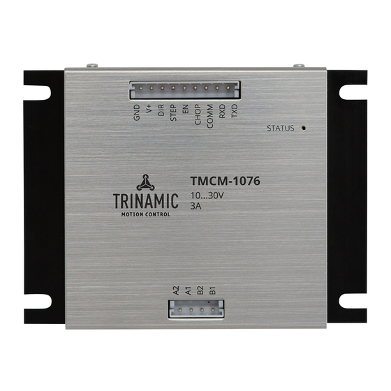
Page 8: Connectors And Leds
TMCM-1076 Hardware Manual • Hardware Version V1.10 | Document Revision V1.00 • 2018-JUN-25 8 / 22 4 Connectors and LEDs Power + I/O Motor Figure 6: TMCM-1076 connectors 4.1 Motor Connector Pin no. Pin name Description Motor phase B pin 1... -
Page 9: Power + I/O Connector
TMCM-1076 Hardware Manual • Hardware Version V1.10 | Document Revision V1.00 • 2018-JUN-25 9 / 22 4.2 Power + I/O Connector Pin no. Pin name Description Supply ground connection, also used for USB serial converter ground connection Supply voltage (... -
Page 10: Ttl Uart Connection
To connect via the TTL UART interface to a host PC, we suggest using a USB serial converter from TTL-UART (5V) to USB interface. Communication with the host PC, for example when using TRINAMIC’s TMCL-IDE, is done via the Virtual COM port installed by the converter driver. -
Page 11: Functional Description
• At power up time, the EN input must be low (= driver stage disabled)! • Optional: Connect UART to a TTL UART interface with 5V logic levels. To con gure your TMCM-1076 connect start the TMCL-IDE and use the parameterization tools. For detailed instructions refer to the TMCM-1076- rmware-manual. -
Page 12: Optically Isolated Inputs With Common Anode Input
12 / 22 5.2 Optically Isolated Inputs with Common Anode Input The control inputs of the TMCM-1076 are optically isolated (not the TTL UART interface). All optocouplers share one common anode (COMM) input as shown in the gure above. TMCM-1076 / 3.3V to +6V... -
Page 13: Optically Isolated Inputs With Common Cathode Input
CHOP Figure 9: Inputs with common anode input with >5V to 24V The series resistors in the TMCM-1076 are 270mOhms. For operation with voltages higher than 5V an additional external resistor is required per input to limit the current. See Table... -
Page 14: Thermal Behavior
TMCM-1076 Hardware Manual • Hardware Version V1.10 | Document Revision V1.00 • 2018-JUN-25 14 / 22 5.4 Thermal Behavior The motor current may be set to the speci ed maximum current of 3A RMS / 4.2A peak for the TMCM- 1076 which is slightly above the maximum speci ed current for the stepper motor options (available as PD57/PD60-x-1076). -
Page 15: Operational Ratings And Characteristics
TMCM-1076 Hardware Manual • Hardware Version V1.10 | Document Revision V1.00 • 2018-JUN-25 15 / 22 6 Operational Ratings and Characteristics 6.1 Absolute Maximum Ratings Parameter Unit Supply voltage Working temperature ° C Motor coil current / sine wave peak... -
Page 16: Functional Characteristics
TMCM-1076 Hardware Manual • Hardware Version V1.10 | Document Revision V1.00 • 2018-JUN-25 16 / 22 TTL UART high level voltage 3.25 T T L TTL UART output voltage T T L_OU T Table 10: Operational ratings of optically isolated inputs and TTL UART interface 6.4 Functional Characteristics... -
Page 17: Abbreviations Used In This Manual
TMCM-1076 Hardware Manual • Hardware Version V1.10 | Document Revision V1.00 • 2018-JUN-25 17 / 22 7 Abbreviations used in this Manual Abbreviation Description COMM Common Anode or common cathode Integrated Development Environment Light Emmitting Diode Root Mean Square value... -
Page 18: Figures Index
TMCM-1076 Hardware Manual • Hardware Version V1.10 | Document Revision V1.00 • 2018-JUN-25 18 / 22 8 Figures Index Motor coil sine wave current using TMCM-1076 connectors ..stealthChop (measured with current Typical application scenario with 5V in- probe) . -
Page 19: Tables Index
TMCM-1076 Hardware Manual • Hardware Version V1.10 | Document Revision V1.00 • 2018-JUN-25 19 / 22 9 Tables Index Order codes modules ..Operational ratings of optically iso- Order codes cable loom . -
Page 20: Supplemental Directives
10.5 Disclaimer: Life Support Systems TRINAMIC Motion Control GmbH & Co. KG does not authorize or warrant any of its products for use in life support systems, without the speci c written consent of TRINAMIC Motion Control GmbH & Co. KG. -
Page 21: Collateral Documents & Tools
In particular, this also applies to the stated possible applications or areas of applications of the product. TRINAMIC products are not designed for and must not be used in connection with any applications where the failure of such products would reasonably be expected to result in signi cant personal injury or death (safety-Critical Applications) without TRINAMIC’s speci c written consent. -
Page 22: Revision History
TMCM-1076 Hardware Manual • Hardware Version V1.10 | Document Revision V1.00 • 2018-JUN-25 22 / 22 11 Revision History 11.1 Hardware Revision Version Date Author Description 1.00 2018-FEB-28 First prototype version. 1.10 2018-APR-09 Pull-ups for opto-isolator changed to lower values (to be compatible with TMCM-1070).
Need help?
Do you have a question about the TMCM-1076 and is the answer not in the manual?
Questions and answers