Sign In
Upload
Manuals
Brands
Binder Manuals
Laboratory Equipment
9140-0092
Binder 9140-0092 Manuals
Manuals and User Guides for Binder 9140-0092. We have
1
Binder 9140-0092 manual available for free PDF download: Operating Manual
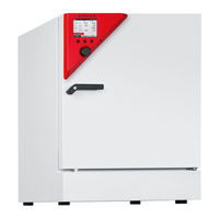
Binder 9140-0092 Operating Manual (145 pages)
CB (E6.1) CO2 - Incubators CO2 – Incubators with O2 control with sterilizable NDIR sensor system for CO2 and microprocessor controller T4.12
Brand:
Binder
| Category:
Laboratory Equipment
| Size: 5 MB
Table of Contents
Table of Contents
2
Safety
6
Legal Considerations
6
Structure of the Safety Instructions
6
Signal Word Panel
6
Safety Alert Symbol
7
Pictograms
7
Word Message Panel Structure
8
Localization / Position of Safety Labels on the Chamber
8
Type Plate
10
General Safety Instructions on Installing and Operating the CO Incubator
11
Precautions When Working with Gases
12
Precautions When Handling Gas Cylinders
14
Intended Use
15
Chamber Description
16
Chamber Overview
17
Instrument Panel
17
Inner Chamber
18
Control Panel on the Rear of the Chamber
20
Completeness of Delivery, Transportation, Storage, and Installation
21
Unpacking, and Checking Equipment and Completeness of Delivery
21
Guidelines for Safe Lifting and Transportation
21
Storage
22
Location of Installation and Ambient Conditions
22
Installation and Connections
26
Shelves
26
Permadry™ Water Pan
26
Connecting the O
27
Control)
27
Gas Connections
28
Connection of the CO Gas Cylinder
29
Connection of the O Gas Cylinder (Chamber with O Control and Optional Alternative Control Range 10 up to 95 Vol.-% O )
30
Connection of the N
31
Gas Cylinder
31
Control)
31
Connecting the Gas Hose to the Chamber Rear (for CO )
32
Gas Cylinder Connection Kits (Option)
33
Electrical Connection
34
Handling and Aligning the Divided Inner Door, Gas Proof (Optional Equipment)
35
Start up
36
Equilibration Time
36
Factory Settings
36
Functional Overview of the T4.12 Chamber Controller
37
Menu Structure
38
General Menu
38
Quick Menu
39
User Menu
40
Operating Modes
41
Activating the "Control Off" Mode or Change to "Fixed Value" Operating Mode
41
Deactivating the O
43
Required Gas Supply of the Chamber with O
43
Control
43
Activating / Deactivating the O Control and O Pressure Alarms
44
N 2 Pressure Alarms
44
Humidity Control of the Permadry™ System
45
Turning on / off the Interior Socket Voltage (with Optional Interior Socket)
46
Performance During and after Power Failure
46
Information
47
Setpoint Entry
48
Setting Ranges
48
Note When Setting High Gas Concentrations
48
Entering the Setpoints Via "Quick Menu
50
Entering the Setpoints Via General Menu
52
Key Lock
54
Directly Activating the Key Lock
55
Automatic Key Lock
55
Changing the Password for Unlocking the Key Lock
57
General Controller Settings
58
Setup Wizard
59
Date and Time Settings
59
Selecting the Menu Language of the T4.12 Controller
61
Setting Display Brightness
61
Changing the Temperature Unit
62
Defining the Data Recording Rate
62
Factory Reset
63
Network Configuration
63
Display of the Network Configuration
67
RS 422 Address (with Optional RS 422 Interface)
68
Display and Entry of the Device Configuration - for Service Purpose
68
Data Transfer Via Usb Interface
69
Exporting Data to USB Drive
69
Importing Data from USB Drive
70
Notifications and Alarms
71
Notifications Overview
71
Alarm Messages Overview
71
Alarm Status
73
Confirming an Active "Set" Alarm
74
Alarm Configuration and Overview
75
List of Active Alarms
75
History - List of All Alarms
76
Activating, Deactivating, and Testing the Alarm Buzzer
77
Activating / Deactivating All Alarm Functions
77
Setting the Delay Time after Opening the Door
78
Tolerance Ranges and Alarm Delay Times
78
Zero-Voltage Relay Alarm Output
82
Event List
83
Graphical Display of the Measured Values
84
Setting the Sampling Rate
84
Defining the Display Range
85
Selecting the Parameters
86
Temperature Safety Devices
87
Overtemperature Protective Device (Class 1)
87
Overtemperature Safety Controller (Temperature Safety Device Class 3.1)
87
Safety Controller Modes
87
Setting the Safety Controller
88
Options
91
Communication Software APT-COM™ 3 Datacontrolsystem (Option)
91
RS 422 Interface (Option)
91
Silicone Access Ports 30 MM / 1.18 In, Closable from both Sides with Silicon Plugs (Option)
91
Interior Socket 230V (Option)
92
Analog Outputs for Temperature and CO (Option)
94
Access Port for Extra-Low Voltage (Option)
94
BINDER Gas Supply Service - External Bottle Changer for CO
95
N 2 or O 2 (Option)
95
Stands
96
Stacking Stand (Option)
96
Stacking Adapter for Direct Thermal Decoupled Stacking (Option)
96
Base on Castors (Option)
96
Reference Measurements
97
CO Reference Measuring
97
Measuring CO 2 Concentration Indirectly Via the Ph of the Cell Medium
97
Directly Via Chemical Indicator Tubes
98
Temperature Reference Measurement
99
Directly with an Electronic Infrared Measuring Device
99
Avoiding Microbial Contamination
99
Cells and Media
99
Laboratory Conditions / Equipment Around the Incubator
99
Working and Behavior in the Lab
100
Chamber Design and Equipment of the CO Incubator
100
Handling the CO Incubator
101
Cleaning, Decontamination / Disinfection, and Sterilization
103
Cleaning
103
Decontamination / Chemical Disinfection of the Chamber
105
Hot-Air Sterilization at 180 °C / 356 °F
106
Overview
106
Performing a Hot-Air Sterilization
107
Aborting the Hot-Air Sterilization - General Procedure
109
Aborting Hot-Air Sterilization after Less than 4 Hours
110
Terminating Successful Sterilization During the Cooling-Down Phase (Abortion after more than 4 Hours)
112
Terminating the Completed Sterilization Cycle
113
Maintenance and Service
115
Maintenance Intervals, Service
115
Checking the Air Jacket Heating Fan
116
Checking the Humidity System Fan
116
Gas Inlet Fine Filter
116
Sending the Chamber Back to BINDER Gmbh
116
Disposal
117
Disposal of the Transport Packing
117
Outer Chamber Packing
117
Packing Inside the Chamber and Equipment
117
Decommissioning
118
Disposal of the Chamber in the Federal Republic of Germany
118
Disposal of the Chamber in the Member States of the EU Except for the Federal Republic of Germany
119
Disposal of the Chamber in Non-Member States of the EU
120
Troubleshooting
121
General
121
Heating
121
Gas Cylinder Pressure too Low
123
Gas Concentration
124
Sterilization
126
Humidity
126
Controller
127
Open Door
127
Technical Description
128
Factory Calibration and Adjustment
128
Over Current Protection
128
Definition of Usable Volume
128
CB Technical Data
129
Equipment and Options
131
Accessories and Spare Parts (Extract)
132
Important Conversion Data for Non-SI Units
133
Conversion Table for Gas Inlet Pressures, Bar - Psi
133
Dimensions CB 60
134
Dimensions CB 160
135
Dimensions CB 220
136
Certificates and Declarations of Conformity
137
EU Declaration of Conformity
137
Product Registration
139
Contamination Clearance Certificate
140
For Chambers Located Outside the USA and Canada
140
For Chambers in the USA and Canada
143
Advertisement
Advertisement
Related Products
Binder 9140-0090
Binder 9140-0091
Binder 9140-0093
Binder 9140-0094
Binder 9140-0095
Binder 9140-0096
Binder 9140-0097
Binder 9140-0098
Binder 9140-0099
Binder 9140-0078
Binder Categories
Climate chamber
Laboratory Equipment
Accessories
Oven
Farm Equipment
More Binder Manuals
Login
Sign In
OR
Sign in with Facebook
Sign in with Google
Upload manual
Upload from disk
Upload from URL