Table of Contents
Advertisement
Quick Links
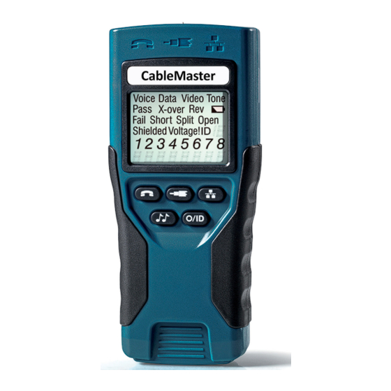
CableMaster
Voice, Data & Video Tester
• Tests Voice (6 wire), Data (8 wire)
and Video (coax)
• Easy to read, extra large 7-segment
LCD screen with large icons
• Tone generation over voice, data and
video cables, with 4 different tones
• RJ (Voice & Data) master remote stores
in bottom of case
• Maps 19 locations at one time
• Tests and indicates pins with shorts,
opens, reversals, miswires and split pairs
• Displays "Pass" icon for correctly wired
T568A/B and crossover/uplink
• Displays "Pass" icon for correctly wired 6-pin
telephone plus "Rev" for reverse-pinned
• Low power consumption for long battery life
• Auto power-off
CM400
USER MANUAL
http://itnetworks.softing.com
Advertisement
Table of Contents

Related Manuals for Softing CableMaster


Summary of Contents for Softing CableMaster
- Page 1 CableMaster CM400 Voice, Data & Video Tester • Tests Voice (6 wire), Data (8 wire) and Video (coax) • Easy to read, extra large 7-segment LCD screen with large icons • Tone generation over voice, data and video cables, with 4 different tones • RJ (Voice & Data) master remote stores in bottom of case • Maps 19 locations at one time • Tests and indicates pins with shorts, opens, reversals, miswires and split pairs • Displays “Pass” icon for correctly wired T568A/B and crossover/uplink • Displays “Pass” icon for correctly wired 6-pin telephone plus “Rev” for reverse-pinned • Low power consumption for long battery life • Auto power-off USER MANUAL http://itnetworks.softing.com...
-
Page 2: Table Of Contents
Using Tone Mode ................20 MAINTENANCE���������������������������������������������������������������������������� 22 Battery Replacement ..............22 Cleaning ..................22 Storage ..................22 CUSTOMER SERVICE �������������������������������������������������������������������� 23 Contacting Softing IT Networks ............. 23 Additional Accessories ..............23 Warranty Information ..............24 Registration ................... 24 Disposal ..................24 Returns ..................24 SPECIFICATIONS ��������������������������������������������������������������������������... -
Page 3: About This Manual
ABOUT THIS MANUAL The CableMaster is a handheld device used by contractors, repair technicians, and other authorized users to test, identify, and detect potential faults in voice, video and data cables. The test unit offers the following three features: Feature Function Continuity... -
Page 4: Terms And Descriptions
CableMaster 400 TERMS AND DESCRIPTIONS Table 2 defines the terms used throughout the document and provides information to assist you with proper operation and understanding of the test unit. Table 2� Terms and Descriptions Terms Description and Uses Coax cable with a single pair (2 pin) wiring system Video cable •... -
Page 5: Safety Information
SAFETY INFORMATION To ensure safe operation of the CableMaster, follow the instructions carefully and observe the warning and caution messages listed in Table 3. Failure to observe warnings can result in severe injury or death and can cause damage to the tester. -
Page 6: Accessories
The accessories listed in Table 4 below are provided with your purchase of the CableMaster. These accessories must be used when operating the unit in order to properly test and identify cables. Refer to the Additional Accessories section for a listing of additional products that can help make testing easier. -
Page 7: Design Features
• Wire mapping remotes for mapping cable runs to wall outlets accompany the CableMaster • Cable test results displayed in wire map format with connector pin numbers • Tests and indicates pins with shorts, opens, reversals, miswires and split pairs •... -
Page 8: Cablemaster Description
RJ11 Jack RJ45 Jack Figure 1. CableMaster JACKS AND CONNECTORS The main unit connectors located at the top of the CableMaster include two RJ Jacks for data and voice cables and one F-Connector for video cables. REMOTE TESTER The remote tester can be detached from the main unit to test cables over a distance. -
Page 9: Lcd Display Screen
Note: The tone tracer probe is sold separately (refer to the Additional Accessories section) PASS/SPECIAL CABLES The second row of the display screen corresponds to the wiring structure of the cable being tested. The CableMaster displays the following three icons:... - Page 10 CableMaster 400 Pass – The “Pass” icon appears if the cable has a properly wired 4-pair T568A/B data cable, a 3-pair one-to-one wired voice cable, or a video cable with no faults. X-over – This icon displays if a properly wired cross-over (uplink) data cable is recognized.
- Page 11 If the pairs are not flashing, the cable is wired properly and a “Pass” icon will appear. The accuracy of the CableMaster is limited to identifying the pin pairs with errors. It cannot identify the individual pin experiencing the error.
-
Page 12: Keypad
The “ID” symbol, located in the third line of the LCD screen, appears when the CableMaster is in Video, Data or ID Mode. When using the wire mapping remotes, the “ID” icon will turn on and the remote ID number will display to its right. The ID number is not displayed if an error occurs, such as “Open”... - Page 13 ID MODE ID Mode is used with wire mapping remotes to ID Mode identify cable runs. • When the CableMaster is Off, one press of this button turns unit on and begins ID mode • ID Mode scans all cable types (voice, video, and data) and...
-
Page 14: Operations
CableMaster 400 OPERATIONS To ensure safe operation of the CableMaster, follow the instructions carefully and pay attention to the warning and caution symbols. Failure to observe warnings can result in severe injury or death and can cause damage to the tester. -
Page 15: Testing Voice Cables
CABLE TESTING GENERAL GUIDELINES The CableMaster tests video, data, and voice cables to detect potential faults, shows a cable’s wire pairing, and examines the physical properties of a cable. Important Points to Note • The RJ jacks for data and voice cables share internal connections within the tester Only one RJ cable can be connected at a time for accurate cable test results. - Page 16 CableMaster 400 1. Insert one end of the cable into the RJ11 jack on the main tester. 2.Place the other end of the cable into the the RJ Jack on the remote tester. 3. Single Test: To run a single test on the 6-position connected voice cable, press the VOICE MODE button.
-
Page 17: Testing Video Cables
TESTING VIDEO CABLES 1. Connect the provided F-Connector coupler to the F-Connector at the top of the main tester (see Figure 6 below). Figure 6. F-Connector on Main Tester 2. Screw one end of the video cable into the F-Connector coupler. 3. Secure a Coax remote to the opposite end of the video cable. 4. -
Page 18: Testing Data Cables
CableMaster 400 TESTING DATA CABLES Testing a data cable is a 2-end test where one end is connected to the main tester and the other end is connected to the remote tester. 1. Plug one end of the data cable into the RJ45 jack on the main tester. -
Page 19: Using Id Mode
The Wire Map will show the pin connections with the crossover. Refer to the LCD Display Screen section for details USING ID MODE The ID functionality of the CableMaster identifies cables using remotes. Each remote isnumbered sequentially to help you easily identify cables. 1. Make sure the CableMaster is turned OFF. -
Page 20: Using Tone Mode
CableMaster 400 • tIf multiple wire mapping remotes are found, the ID or fault is displayed automatically in sequence Video 123 4 5 67 8 Figure 10. Detected Coax Remote USING TONE MODE Tone Mode is used to trace cable runs and locate faults by sound. Selection of this mode emits a cadence from the main tester through the connected cable. - Page 21 • The cable type icon appears at the top of the screen. • The “Tone” icon displays in the upper right corner of the screen. • Three progression bars appear above pins 7 and 8 demonstrating you are in active Tone Mode.
-
Page 22: Maintenance
CableMaster 400 MAINTENANCE BATTERY REPLACEMENT 1. Remove the single screw, located in the middle of the back of the CableMaster, with a #1 Philips head screwdriver. 2. Take out the old battery and disconnect the battery cable. 3. Replace the old battery with an ANSI 1604A, 9 volt alkaline battery (Energizer 522, Duracell MN1604). -
Page 23: Customer Service
CUSTOMER SERVICE CONTACTING SOFTING IT NETWORKST For technical information and support please contact the Softing Office in your country. Please see the last page of this manual or go to http://itnetworks.softing.com. ADDITIONAL ACCESSORIES Table 8 below lists the additional accessories that are available for purchase through Softing IT Networks GmbH. -
Page 24: Warranty Information
Should any parts or workmanship prove defective, Softing IT Networks GmbH will re- pair or replace at Softing IT Networks’ option, at no cost to the Buyer except for ship- ping costs from the Buyer’s location to Softing IT Networks. This is Buyer’s SOLE AND EXCLUSIVE REMEDY under this Agreement. -
Page 25: Specifications
SPECIFICATIONS Specifications Description Physical Size: 16.3 x 7.1 x 3.6 cm (6.4 x 2.8 x 1.4 inches) Weight: 256 grams (9.0 oz) with battery and remote-end of tester Dimensions 1 9V alkaline battery Power Active: 425 hours Standby: 4 years Parameters refer to the maximum voltage that can be applied to Maximum any 2 connector pins without causing damage to the tester. -
Page 26: Appendix: Cable Wiring And Display Screen
CableMaster 400 APPENDIX: CABLE WIRING AND DISPLAY SCREEN Cable Wiring Display Screen PROPERLY WIRED T568A DATA CABLE T568B is electrically identical to T568A, but swaps the green and orange pairs. Either standard will work as long as the same standard is used at both ends of a run or patch cable. - Page 27 Cable Wiring Display Screen T568A CABLE WITH A SHORT AND AN OPEN The 1-2 pair pins are shorted together and the 7-8 pair is open. The pins with the errors are flashing. Dash lines (-) on the bottom (remote) display line indicate the short, while no numbers on the bottom line indicate the open pair. T568A CABLE WITH A MISWIRE AND UNRECOGNIZED CONTINUITY 1 and 2 pins on the main tester are connected to pins 2 and 1 at the remote-end.
- Page 28 E-mail: info.france@softing.com Italy Softing Italia Srl. Cesano Boscone, Milano Phone: +39 02 4505171 E-mail: info@softingitalia.it Austria Buxbaum Automation GmbH Eisenstadt Phone: +43 2682 7045 60 E-mail: office@myautomation.at For technical information and support please contact the Softing office in your country. http://itnetworks.softing.com...
Need help?
Do you have a question about the CableMaster and is the answer not in the manual?
Questions and answers