Sign In
Upload
Download
Table of Contents
Contents
Add to my manuals
Delete from my manuals
Share
URL of this page:
HTML Link:
Bookmark this page
Add
Manual will be automatically added to "My Manuals"
Print this page
×
Bookmark added
×
Added to my manuals
Manuals
Brands
Softing Manuals
Test Equipment
BC-600-PB
Manual
Softing BC-600-PB Manual
Hide thumbs
1
2
3
Table Of Contents
4
5
6
7
8
9
10
11
12
13
14
15
16
17
18
19
20
21
22
23
24
25
26
27
28
29
30
31
32
33
34
35
36
37
38
39
40
41
42
43
44
page
of
44
Go
/
44
Contents
Table of Contents
Troubleshooting
Bookmarks
Table of Contents
Segment Status
Table of Contents
1 Introduction
Introduction General
Test Functions
Stand-Alone Mode of Operation
PC Mode of Operation
2 Delivery Scope
3 Optional Accessories
D-Sub Adapter Cable for Testing Live Systems
Adapter Set for M12 Connection Technology
Fieldbus Shield Digital Leakage Current Clamp
Portable Power Supply
Service Interface for PROFIBUS DP
Connection Type D-Sub
Connection Type M12
4 Connectors and Controls
5 Power Supply and Auto Power on
Power-Up Behaviour Without USB Connection
Power-Up Behaviour When USB Connected
6 Software Installation
Connection to a PC
7 Connection to PROFIBUS
Basics
Warning Notice for Testing a Live Bus
Connection Types
Adapter Cable
Strain Relief
Test Locations
Simple Connection for Tests During System Shutdown
Connection for Testing a Live Bus
Connection Via D-Sub Connector with Service Socket
Direct Cable Connection
Connection Via M12 Connector
Master Simulator and Topology Scan
Special Case: Active Devices at both Ends of the Bus
8 Display and Control in Stand-Alone Mode
Main Display
Operating Concept
Functions
Live Status Function
Bus Status Summary
Segment Status 1
Segment Status 2
Station Status
Quick Test Function
Trend Function
Master Simulator Function
Settings and Help Functions
9 Data Import into the PC
10 Firmware Update
11 Maintenance and Servicing
12 Troubleshooting
13 Specifications
14 General Notes
Lithium Battery
CE Conformity
Advertisement
Quick Links
Download this manual
Manual
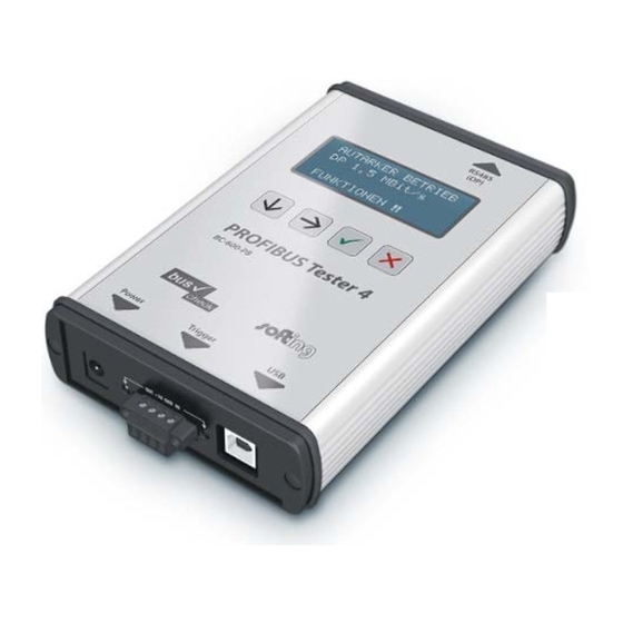
PROFIBUS Tester 4
BC-600-PB
FW version 1.13 (rev. 17)
Revision 2013-05-31
Table of
Contents
Previous
Page
Next
Page
1
2
3
4
5
Advertisement
Table of Contents
Need help?
Do you have a question about the BC-600-PB and is the answer not in the manual?
Ask a question
Questions and answers
Related Manuals for Softing BC-600-PB
Test Equipment Softing PROFIBUS Tester 5 User Manual
(60 pages)
Test Equipment Softing BC-700-PB User Manual
Profibus tester 5 (60 pages)
Test Equipment Softing PROFIBUS Tester 4 BC-600-PB Manual
(44 pages)
Test Equipment Softing CableMaster CM500 User Manual
Voice, data & video tester with length measurement (24 pages)
Test Equipment Softing Wire Xpert WX Series User Manual
(57 pages)
Test Equipment Softing NetXpert XG2 Manual
(66 pages)
Test Equipment Softing CableMaster User Manual
Voice, data & video tester (28 pages)
Test Equipment Softing CableMaster 210 Manual
(6 pages)
Test Equipment Softing CableMaster CM800 User Manual
Identify, monitor, and correct lan issues (30 pages)
Test Equipment Softing WireXpert Cat6A+Adapters User Manual
(25 pages)
Test Equipment Softing WireXpert MP C8 User Manual
(87 pages)
Test Equipment Softing CableMaster CM600 Quick Start Manual
(16 pages)
Test Equipment Softing NetXpert XG2 PLUS Quick Start Manual
(56 pages)
Test Equipment Softing CableMaster 210 Quick Start Manual
(13 pages)
This manual is also suitable for:
Profibus tester 4
Table of Contents
Print
Rename the bookmark
Delete bookmark?
Delete from my manuals?
Login
Sign In
OR
Sign in with Facebook
Sign in with Google
Upload manual
Upload from disk
Upload from URL


Need help?
Do you have a question about the BC-600-PB and is the answer not in the manual?
Questions and answers