Table of Contents
Advertisement
Quick Links
User Manual
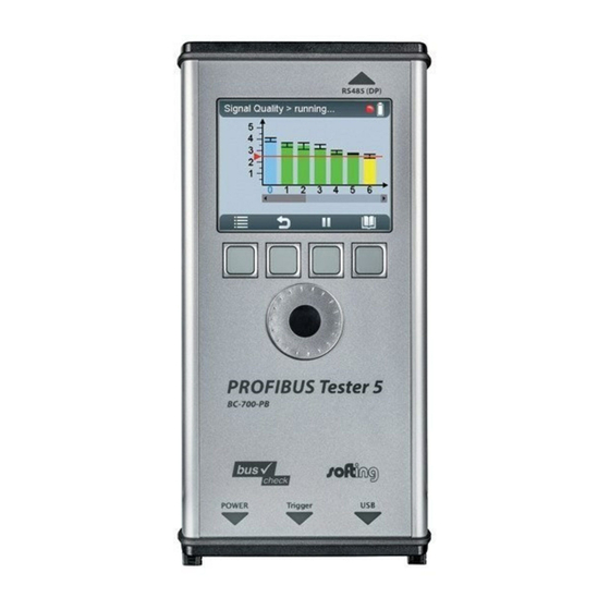
PROFIBUS Tester 5 BC-700-PB
Getting Started with PROFIBUS Tester 5 BC-700-PB
Insert graphic file
from e.g.
\\Sfiler\iap_intern\10_Marketing\02_Materials\02-11_Photos
For positioning data see
..\<projectdirectory>\Images\readme_insert_graphics.txt"
Version: MMA-NN-006005-EN-1408-1.01
© Copyright 2014 Softing Industrial Automation GmbH
Advertisement
Table of Contents

Subscribe to Our Youtube Channel
Related Manuals for Softing BC-700-PB


Summary of Contents for Softing BC-700-PB
- Page 1 User Manual PROFIBUS Tester 5 BC-700-PB Getting Started with PROFIBUS Tester 5 BC-700-PB Insert graphic file from e.g. \\Sfiler\iap_intern\10_Marketing\02_Materials\02-11_Photos For positioning data see ..\<projectdirectory>\Images\readme_insert_graphics.txt" Version: MMA-NN-006005-EN-1408-1.01 © Copyright 2014 Softing Industrial Automation GmbH...
- Page 2 85540 Haar / Germany Tel: + 49 89 4 56 56-0 Fax: + 49 89 4 56 56-488 Internet: http://industrial.softing.com Email: info.automation@softing.com Support: support.automation@softing.com The latest version of this manual is also available in the Softing download area at: http://industrial.softing.com.
-
Page 3: Table Of Contents
Power-off and sleep mode ..................19 Chapter 4 Install software and connect to PC ..................20 Chapter 5 Connection to PROFIBUS ..................21 Chapter 6 General information ....................21 6.1.1 Possible side effects when testing a live bus ........................21 PROFIBUS Tester BC-700-PB - User Manual... - Page 4 ....................47 13.2 List of fault indications and remedial measures ....................48 13.3 Metering the cable segment length correctly ....................51 Notes on battery use ..................53 Chapter 14 14.1 Lithium backup battery ....................53 PROFIBUS Tester BC-700-PB - User Manual...
- Page 5 ........................55 14.2.4 Storage and transportation ........................55 14.2.5 Battery life ........................55 14.2.6 Battery warranty ........................55 Technical data ..................56 Chapter 15 Declarations by the manufacturer ..................58 Chapter 16 Recycling ..................59 Chapter 17 PROFIBUS Tester BC-700-PB - User Manual...
- Page 6 This page is intentionally left blank.
-
Page 7: Chapter 1 Introduction
Introduction About PROFIBUS Tester 5 BC-700-PB The PROFIBUS Tester 5 BC-700-PB is a powerful tool that allows full testing of the bus physics and bus communication on PROFIBUS DP and PROFIBUS PA segments (option). Using the integrated master simulator, you can also test the bus physics if the PLC is currently not in operation, or individually check "suspicious"... -
Page 8: Conventions Used
Chapter 1 - Introduction 1.2.3 Conventions used The following conventions are used throughout Softing customer documentation: Keys, buttons, menu items, commands and Open Start Control Panel other elements involving user interaction are Programs set in bold font and menu sequences are... -
Page 9: Optional Accessories
CD-ROM with driver software, PC software and detailed integrated help system in English and German PROFIBUS Tester 5 BC-700-PB User Manual and Quick Startup Guide for the PROFIBUS Diagnostics Suite PC software. Figure 1: PROFIBUS Tester 5 BC-700-PB with carrying case Optional accessories 1.4.1... -
Page 10: Adapter Set For M12 Connection Technology
The digital leakage current clamp is supplied in a handy case, including measuring cables. There is also an empty compartment for the fieldbus shield digital leakage current clamp in the carrying case of the PROFIBUS Tester 5 BC-700-PB. Figure 4: Fieldbus shield digital leakage current clamp Softing Order No.: PB-LSZ-CHB3... -
Page 11: Spare Rechargeable Battery
DC feeding voltage greater than 9 Volts. Figure 5: BC-700-H1 Adapter Figure 6: Supplied test equipment set for connecting to PROFIBUS PA segments Softing Oder No.: DDL-NL-006010 (Adapter and test equipment) 1.4.5 Spare rechargeable battery Intensive use of PROFIBUS-Tester 5 during the work day may exhaust the rechargeable battery faster than expected. -
Page 12: Service Interfaces For Profibus Dp
The compact unit is rail mounted like a terminal block and powered by an external 24 VDC power supply. The package includes a 90° angled PROFIBUS connector with a switchable terminating resistor. Figure 8: D-sub service interface for testing a live bus Softing Order No.: BC-PBMB-PB-S PROFIBUS Tester BC-700-PB - User Manual... -
Page 13: Connection Type M12
System requirements Hardware USB 2.0 Operating system Windows XP (with Microsoft Windows .NET Framework 3.5 installed) or Windows 7 (32 bit or 64 bit) or Windows 8 and Windows 8.1 (32 bit or 64 bit) PROFIBUS Tester BC-700-PB - User Manual... -
Page 14: Connectors And Controls
Chapter 1 - Introduction Connectors and controls Figure 10: Connectors, buttons and status displays on the PROFIBUS Tester 5 BC-700- PROFIBUS Tester BC-700-PB - User Manual... -
Page 15: Chapter 2 Prepare Device
Insert the provided battery (standard accessory). The connecting plug is protected against polarity reversal. Check that the connecting plug is properly connected. Mount the back cover and fix the screws. PROFIBUS Tester BC-700-PB - User Manual... -
Page 16: Charge Battery
Hint You do not need to charge the battery for a specific length of time, and you can use the device while it is charging. PROFIBUS Tester BC-700-PB - User Manual... -
Page 17: Chapter 3 Startup
Display and controls in stand-alone mode ) and is immediately ready for testing. During program start-up the splash screen is shown for a few seconds and displays "USB NOT CONNECTED": Figure 12: Splash screen – starting without USB-connection PROFIBUS Tester BC-700-PB - User Manual... -
Page 18: Power-Up Behaviour With Usb Connected
At this point, you can also start a firmware update instead of using the control and evaluation software (refer also to Firmware update The display shows: Figure 14: Display at testing with PC software PROFIBUS Tester BC-700-PB - User Manual... -
Page 19: Chapter 4 Power-Off And Sleep Mode
The lastly shown menu screen will be displayed which was active before changing to sleep mode. Automatic power-off If the PROFIBUS-Tester 5 is in sleep mode for more than 2 hours, it will automatically power-off. PROFIBUS Tester BC-700-PB - User Manual... -
Page 20: Chapter 5 Install Software And Connect To Pc
We recommend connecting the unit directly to an USB port (USB 2.0) on the PC or on the notebook. When you use external USB hubs, notebook docking stations or USB 3.0 ports for connection, problems may occur. PROFIBUS Tester BC-700-PB - User Manual... -
Page 21: Chapter 6 Connection To Profibus
Due to the daisy-chain topology, the connection points of the bus stations are the typical points for connecting the test tool. PROFIBUS Tester BC-700-PB - User Manual... -
Page 22: Adapter Cable
Figure 15: Unallowed cascading of D-sub connectors 6.1.4 Strain relief Use the strain relief supplied with the test tool. Thus you avoid the device from falling down. Figure 16: Recommended use of retaining strap PROFIBUS Tester BC-700-PB - User Manual... -
Page 23: Using The Security Lock Port
Simple connection for tests during system shutdown If all bus stations provide D-sub connectors with an additional service socket, you can simply plug in the PROFIBUS Tester 5 at that socket (see figure below). If a D-sub PROFIBUS Tester BC-700-PB - User Manual... -
Page 24: Connection For Testing A Live Bus (Dp)
If no suitable connection points are available in the existing installation, it is recommended to install them during system shutdown. This will make future maintenance work much easier. PROFIBUS Tester BC-700-PB - User Manual... -
Page 25: Connection Via D-Sub Connector With Service Socket
Connection via D-sub connector with service socket If all bus stations provide D-sub connectors with an additional service socket, you can simply plug in the PROFIBUS Tester 5 at that socket: Figure 19: Connection points for the D-sub adapter cable PROFIBUS Tester BC-700-PB - User Manual... -
Page 26: Direct Cable Connection
To test a live PROFIBUS, you will need additional D-sub service interface of the type BC- PBMB-PB-S (see Service interfaces for PROFIBUS DP Figure 20: Service interface provide connection points at direct cable connection PROFIBUS Tester BC-700-PB - User Manual... -
Page 27: Connection Via M12 Connector
The master simulator allows checking the bus cabling and the station addresses during installation and commissioning, when the PLC (master) is not in operation yet. In addition, you can use this mode to check individual "suspicious" bus stations that have been disconnected from the bus. PROFIBUS Tester BC-700-PB - User Manual... - Page 28 PROFIBUS connector needs to be unplugged and connected directly to the PROFIBUS Tester 5 BC-700-PB. The bus termination in the device connector will then be powered by the PROFIBUS Tester 5 BC- 700-PB.
-
Page 29: Connecting To Profibus-Pa Networks
Field distributors and T pieces are widely used. As opposed to PROFIBUS DP, spur cables are allowed to a limited extent for PROFIBUS PA. The following types of DP/PA fieldbus couplers are the most common: Simatic DP/PA couplers from Siemens, also as part of DP/PA links PROFIBUS Tester BC-700-PB - User Manual... - Page 30 An appropriate connection point is located directly at the DP/PA coupler. At this point, the tool can continue to analyze the bus communication even when lines are interrupted. The measurements are not affected by repeaters or field barriers. PROFIBUS Tester BC-700-PB - User Manual...
-
Page 31: Requirements For Analyzing A Live Bus
The PROFIBUS Tester 5 and BC-700-H1 adapter must not be used in hazardous areas and must not be connected to an intrinsically safe MBP-IS segment (blue terminals of fieldbus coupler; in some cases blue bus cables). PROFIBUS Tester BC-700-PB - User Manual... -
Page 32: Chapter 7 Display And Controls In Stand-Alone Mode
Control information is shown at the lower edge of the user interface. The meaning of the four softkeys is explained in Operating functions PROFIBUS Tester BC-700-PB - User Manual... - Page 33 (cursor). Error messages are displayed in error dialogs. The PROFIBUS-Tester 5 contains a context-sensitive online help, which is shown in quick reference dialogs using a smaller font size. PROFIBUS Tester BC-700-PB - User Manual...
-
Page 34: Operating Functions And Softkeys
Confirm/ select (central push button in scroll wheel) Start a stopped function Stop a running function Request details for selected elements (press briefly) or Open context-sensitive reference (press button approx. for 2 seconds) Open context-sensitive reference PROFIBUS Tester BC-700-PB - User Manual... -
Page 35: Device Status
0.5 V to 0.6 V is a sign that no power is supplied to one of the two bus terminations. Master simulator is active. You can start the master simulator from the "Extras > Master simulator" menu. PROFIBUS Tester BC-700-PB - User Manual... -
Page 36: Menu Functions
Configuration proper detection of line length, compliance with maximum allowed segment length as well as for proper documentation of test results. Please give full particulars with respect to the configuration of each cable segment. PROFIBUS Tester BC-700-PB - User Manual... - Page 37 Therefore, all stations behind the same repeater will have identical quality test results. When using repeaters, you will thus have to test each segment separately. One test location belongs exclusively to one segment. PROFIBUS Tester BC-700-PB - User Manual...
- Page 38 It is recommended to activate the automatic profile "economy". Language Here you can select the operating language Hardware Hardware information is displayed here (version- and Information serial numbers). License Here you can obtain licensing information PROFIBUS Tester BC-700-PB - User Manual...
-
Page 39: Organize And Store Test Results
Enter the network name (e.g. "engine production"). Use the Edit network sub-function and rename the default segment (e.g. to "heating") and add two new segments (e.g. "foundry" and "conveyor belt"). Use the Test locations function and generate six test locations. PROFIBUS Tester BC-700-PB - User Manual... - Page 40 Assign test location to segments. You can do this in Test locations or in Networks Edit Network Edit segment-subfunction. Figure 30: Example network comprising three segments, 13 PROFIBUS stations, 2 repeaters and 6 recommended test locations (two per segment) PROFIBUS Tester BC-700-PB - User Manual...
-
Page 41: Chapter 8 Import Data Into The Pc
PC software. To do this, start the PROFIBUS Diagnostics Suite. Connect the PROFIBUS Tester 5 BC-700-PB to the PC via USB. An additional Import Test Data dialog box appears automatically showing the test data previously saved: Figure 31: Importing test data... -
Page 42: Chapter 9 Licenses
In PC mode of operation in conjunction with the PC software PB-DIAG-SUITE the corresponding functions are blocked, too. When USB is connected you can view the license activation status in PC-software PB-DIAG-SUITE, too (Help Hardware Info). PROFIBUS Tester BC-700-PB - User Manual... -
Page 43: Chapter 10 Firmware Update
Install software and connect to PC ) and allow access to new or improved functionality. How to update the firmware is described in detail in the separate PROFIBUS Diagnostics Suite – Quick Startup Guide. PROFIBUS Tester BC-700-PB - User Manual... -
Page 44: Chapter 11 Maintenance And Service
Exhaustive discharge and overcharge or exhaustive operation of the device in conjunction with very high or low temperatures will accelerate the battery ageing process (refer to Notes on battery use) PROFIBUS Tester BC-700-PB - User Manual... -
Page 45: Chapter 12 Troubleshooting
Missing license visible respectively Out-dated firmware version is in use Remedy: Please check your bill of delivery if the license is included in your order. Please download the latest firmware version PROFIBUS Tester BC-700-PB - User Manual... - Page 46 Optional: Press the key combination [Softkey 1] + [Softkey 4] during switch-on of the device. Detailed information about self-testing is shown. You can find support contact data on the cover sheet's back side of this document. PROFIBUS Tester BC-700-PB - User Manual...
-
Page 47: Chapter 13 Tips And Tricks For Cable Testing
The baudrate (entered by user) and the The detected cable segment length detected cable segment length fit together exceeds the limit value specified by PI according to PI recommendation (PROFIBUS PROFINET International) (PROFIBUS PROFINET International) PROFIBUS Tester BC-700-PB - User Manual... -
Page 48: List Of Fault Indications And Remedial Measures
PROFIBUS-connector. In rare cases electromagnetic shielding may be disrupted intentionally in order to avoid electromagnetic interferences. Please check this issue with the planning personnel of the PROFIBUS-facility. PROFIBUS Tester BC-700-PB - User Manual... - Page 49 Please terminators. Please make sure, that every bus terminator on remove terminators. every PROFIBUS-connector is switched off or is deactivated. Please take into consideration, that dip-switches for switching on/off bus terminators may be defective. PROFIBUS Tester BC-700-PB - User Manual...
- Page 50 PROFIBUS- connectors. The incoming connector is marked with "IN", an incoming arrow or "A1/B1". Please be also on the lookout for PROFIBUS-cables which have been connected by mistake to the outgoing connector. PROFIBUS Tester BC-700-PB - User Manual...
-
Page 51: Metering The Cable Segment Length Correctly
The series inductance within the 12 MBit/s PROFIBUS-connectors act like a delay element on the cable with respect to impulse reflectometry. Every connector corresponds to approx. 50 cm cable length. PROFIBUS Tester BC-700-PB - User Manual... - Page 52 PROFIBUS devices, which are connected to the line by means of 12 MBit/s Sub-D type connectors. Without indicating the number of connectors and devices the PROFIBUS Tester 5 BC-700-PB will detect a total cable segment length of 64 meters, which corresponds to a systematic error of measurement of approx. 28 %. The more precise you will enter the number of connectors and devices into the segment configuration, the more precise the length indication will be (cable segment length or distance to error).
-
Page 53: Chapter 14 Notes On Battery Use
CAUTION The rechargeable battery pack contains < 2 g Lithium. Softing Industrial Automation GmbH, its distributors or retailers assume no liability for failures to comply with these warnings and safety guidelines. By purchasing this battery, the buyer assumes all risks associated with lithium batteries. -
Page 54: Charging
) in order to charge the battery. Set voltage and current correctly (failure to do so can cause fire). Never charge batteries unattended. Charge in an isolated area, away from other flammable materials. For operating temperatures while charging refer to Specifications (operating temperature). PROFIBUS Tester BC-700-PB - User Manual... -
Page 55: Discharging
Misuse, abuse, incorrect charging and other inappropriate use of this product are not covered under warranty. If you do not agree with these conditions, return the lithium polymer battery immediately and before any use. PROFIBUS Tester BC-700-PB - User Manual... -
Page 56: Chapter 15 Technical Data
Complete tool with carrying case, without accessories: approx. 4.2 kg Protection class IP 20 Permissible ambient Operating temperature 0 .. 50 °C conditions Storage temperature -20 .. 70 °C, Air humidity 10 .. 90% without condensation Conformity CE, FCC, VCCI PROFIBUS Tester BC-700-PB - User Manual... - Page 57 Operation Via graphical color display, four function keys and scroll wheel including central push-button or via PC/notebook. Localization of the display texts: English and German PC operating PROFIBUS Diagnostic Suite, see separate documentation software PROFIBUS Tester BC-700-PB - User Manual...
-
Page 58: Chapter 16 Declarations By The Manufacturer
- Immunity for industrial environments EN 61326-1:2013 A Declaration of Conformity in compliance with the above standards has been made and can be requested from Softing Industrial Automation GmbH. Note To fulfill the EMC requirements, the other components (AC adapter, PROFIBUS stations, etc.) also have to meet the EMC requirements. -
Page 59: Chapter 17 Recycling
**It is very important that customers understand and follow all laws regarding the proper decontamination and safe disposal of electrical equipment. For Softing products bearing this label please contact your dealer or local Softing office for details on the take back program that will facilitate the proper collection, treatment, recovery, recycling and safe disposal of device. - Page 60 Related Documents PROFIBUS Diagnostics Suite - User Manual "Getting Started" - PB-DIAG-SUITE online help Softing Industrial Automation GmbH Richard-Reitzner-Allee 6 85540 Haar / Germany Tel: + 49 89 4 56 56-0 Fax: + 49 89 4 56 56-488 Internet: http://industrial.softing.com Email: info.automation@softing.com...
Need help?
Do you have a question about the BC-700-PB and is the answer not in the manual?
Questions and answers