
Related Manuals for Emerson Rosemount 2240S


Summary of Contents for Emerson Rosemount 2240S
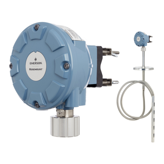
- Page 1 Reference Manual 00809-0100-2240, Rev DA October 2017 ™ Rosemount 2240S Multi-Input Temperature Transmitter...
-
Page 3: Table Of Contents
Reference Manual Contents 00809-0100-2240, Rev DA October 2017 Contents 1Section 1: Introduction 1.1 Safety messages..............1 1.2 Manual overview . - Page 4 Contents Reference Manual 00809-0100-2240, Rev DA October 2017 4.4 Electrical installation ............. . 33 4.4.1 Cable/conduit entries .
- Page 5 Reference Manual Contents 00809-0100-2240, Rev DA October 2017 5.9 General block information ............71 5.9.1 Modes .
- Page 6 Contents Reference Manual 00809-0100-2240, Rev DA October 2017 6Section 6: Service and Troubleshooting 6.1 Safety messages..............107 6.2 Service .
- Page 7 Reference Manual Contents 00809-0100-2240, Rev DA October 2017 A.2 General specifications............141 A.2.1 Number of spot elements and wiring .
- Page 8 Contents Reference Manual 00809-0100-2240, Rev DA October 2017 A.7 Environmental specifications............143 A.7.1 Ambient temperature .
-
Page 9: Spare Parts
Read this manual before working with the product. For personal and system safety, and for optimum product performance, make sure you thoroughly understand the contents before installing, using, or maintaining this product. For equipment service or support needs, contact your local Emerson Automation Solutions/Rosemount Tank Gauging representative. Spare Parts Any substitution of non-recognized spare parts may jeopardize safety. - Page 10 Title Page Reference Manual 00809-0100-2240, Rev DA October 2017 viii Title Page...
-
Page 11: Safety Messages
Reference Manual Introduction 00809-0100-2240, Rev DA October 2017 Section 1 Introduction Safety messages ..............page 1 Manual overview . -
Page 12: Manual Overview
This manual provides installation, configuration, and maintenance information for the Rosemount 2240S Multi-input Temperature Transmitter. The manual is based on a typical Rosemount Tank Gauging system with a Rosemount 2410 Tank Hub connected to supported devices such as the Rosemount 2240S ™... -
Page 13: Technical Documentation
Rosemount 2410 Tank Hub (00809-0100-2410) Rosemount 5900S Radar Level Gauge (00809-0100-5900) Rosemount 5900C Radar Level Gauge (00809-0100-5901) Rosemount 2240S Multi-Input Temperature Transmitter (00809-0100-2240) Rosemount 2230 Graphical Field Display (00809-0100-2230) Rosemount 5300 Series Guided Wave Radar (00809-0100-4530) ... -
Page 14: Service Support
Reference Manual Introduction 00809-0100-2240, Rev DA October 2017 Service support For service support contact the nearest Emerson Automation Solutions/Rosemount Tank Gauging represen- tative. Contact information can be found on the web site Emerson Automation Solutions/Rosemount Tank Gauging. Product recycling/disposal Recycling of equipment and packaging should be taken into consideration and disposed of in accordance with local and national legislation/regulations. -
Page 15: Packing Material
Reference Manual Introduction 00809-0100-2240, Rev DA October 2017 Packing material Rosemount Tank Radar AB is fully certified according to ISO 14001 environmental standards. By recycling the corrugated paperboard, or wooden boxes, used for shipping our products you can contribute to take care of the environment. - Page 16 Reference Manual Introduction 00809-0100-2240, Rev DA October 2017 Introduction...
-
Page 17: Introduction
The Rosemount 2240S Multi-input Temperature Transmitter can connect up to sixteen 3- or 4-wire temperature spot elements and an integrated water level sensor. The Rosemount 2240S sends measurement data, such as temperature and water level, via the intrinsically safe 2-wire Tankbus , to a Rosemount 2410 Tank Hub. -
Page 18: Components
Reference Manual 00809-0100-2240, Rev DA October 2017 Components Figure 2-2. Rosemount 2240S components A. Cover. B. Entries (x 3) of type ½ - 14 NPT. C. Lock nut for connection of Multi Spot Temperature sensor and Water Level Sensors (MST/WLS). -
Page 19: System Overview
Reference Manual Overview 00809-0100-2240, Rev DA October 2017 System overview The Rosemount Tank Gauging system is a state-of-the art inventory and custody transfer radar tank level gauging system. It is developed for a wide range of applications at refineries, tank farms and fuel depots, and fulfills the highest requirements on performance and safety. - Page 20 Overview Reference Manual 00809-0100-2240, Rev DA October 2017 Figure 2-3. Rosemount Tank Gauging system architecture Rosemount 2240S Rosemount 5900S Temperature Transmitter NON-HAZARDOUS AREA HAZARDOUS AREA Radar Level Gauge Rosemount TankMaster PC Rosemount 2230 Display Rosemount 2410 Tank Hub Rosemount 3051S...
- Page 21 Reference Manual Overview 00809-0100-2240, Rev DA October 2017 Figure 2-4. Rosemount Tank Gauging system architecture for wireless systems NON-HAZARDOUS AREA HAZARDOUS AREA Rosemount 5900S Rosemount 2240S Radar Level Gauge Temperature Transmitter Emerson Wireless 775 THUM Adapter Rosemount TankMaster PC Rosemount 2230...
- Page 22 Reference Manual 00809-0100-2240, Rev DA October 2017 Figure 2-5. Rosemount Tank Gauging system architecture in a F fieldbus network OUNDATION Rosemount 5900S Rosemount 2240S NON-HAZARDOUS AREA HAZARDOUS AREA Temperature Transmitter Radar Level Gauge Rosemount 2230 Display Rosemount 3051S Pressure Transmitter...
- Page 23 Reference Manual Overview 00809-0100-2240, Rev DA October 2017 TankMaster HMI Software Rosemount TankMaster is a powerful Windows-based Human Machine Interface (HMI) for complete tank inventory management. It provides configuration, service, set-up, inventory, and custody transfer functions for Rosemount Tank Gauging systems and other supported instruments. ®...
- Page 24 ™ inputs/outputs. By connecting an Emerson Wireless 775 THUM Adapter to the IS HART 4-20 mA output, the tank hub is capable of wireless communication with an Emerson Wireless Gateway in a ® WirelessHART network. Rosemount 5900S Radar Level Gauge The Rosemount 5900S Radar Level Gauge is an intelligent instrument for measuring the product level inside a tank.
- Page 25 An Emerson Wireless 775 THUM Adapter allows wireless communication between a Rosemount 2410 Tank Hub and an Emerson Wireless Gateway. The gateway is the network manager that provides an interface between field devices and the TankMaster inventory software or host / DCS systems.
-
Page 26: Getting Started
4. Connect the Rosemount 2410 Tank Hub to the Rosemount 2460 System Hub. 5. Connect the field devices, such as a Rosemount 5900S Radar Level Gauge and a Rosemount 2240S Multi-input Temperature Transmitter, to the Rosemount 2410 Tank Hub via the Tankbus. -
Page 27: Installation Procedure
Reference Manual Overview 00809-0100-2240, Rev DA October 2017 Installation procedure Follow these steps for proper installation of the Rosemount 2240S: 1. Install the temperature sensor/WLS (Section 3: MST/WLS Installation). 2. Review mounting considerations for the 2240S (“Installation considerations” on page 29). - Page 28 Reference Manual Overview 00809-0100-2240, Rev DA October 2017 Overview...
-
Page 29: Safety Messages
MST/WLS Installation Reference Manual October 2017 00809-0100-2240, Rev DA Section 3 MST/WLS Installation Safety messages ..............page 19 Installation considerations . - Page 30 MST/WLS Installation Reference Manual 00809-0100-2240, Rev DA October 2017 High voltage that may be present on leads could cause electrical shock. Avoid contact with leads and terminals. ™ Make sure the main power to the Rosemount 2240S is off and the lines to any other external power sources are disconnected or not powered while wiring the gauge.
-
Page 31: Installation Considerations
Temperature and Water Level Sensors should be located as far away as possible from heating coils and mixers. In case the flexible tube is damaged, please contact Emerson Automation Solutions/Rosemount Tank Gauging. Do not attempt to fix or rebuild the temperature sensor since this may cause serious malfunctions ... -
Page 32: Multiple Spot Temperature Sensor
The spot elements are placed in a flexible gas tight tube made of stainless steel which can be anchored to the tank bottom, see “Installing a temperature sensor tube” on page Up to 16 Pt100 temperature elements can be connected to a Rosemount 2240S Multi-input Temperature Transmitter. 3.3.1 Installation on fixed roof tanks On fixed roof tanks the MST is attached to a flange mounted on a suitable nozzle. -
Page 33: Installation On Floating Roof Tanks
Reference Manual MST/WLS Installation 00809-0100-2240, Rev DA October 2017 3.3.2 Installation on floating roof tanks On floating roof tanks the temperature elements can be mounted in a still-pipe as illustrated in Figure 3-2 or in other suitable roof openings. Figure 3-2. Installation of multiple spot temperature elements in still-pipe Maximum level Min. -
Page 34: Custody Transfer Applications
For Custody Transfer applications, API chapter 7 recommends a minimum of one temperature element per 3 meters (10 feet) as illustrated in Figure 3-3. Emerson Automation Solutions/Rosemount Tank Gauging may in some cases recommend even more temperature elements for Custody Transfer tanks, depending on how the tanks are operated. -
Page 35: Water Level Sensor
Reference Manual MST/WLS Installation 00809-0100-2240, Rev DA October 2017 Water Level Sensor The water level sensor (WLS) probe, with integrated temperature elements, is attached at the lower end of the flexible protection tube. A weight is attached to stabilize the tube as illustrated in Figure 3-4. -
Page 36: Installing A Temperature Sensor Tube
3. When the tube is placed on the nozzle, adjust the vertical position with the lock nuts. If a weight is placed at the end of the tube, it should barely touch the tank bottom. 4. Install the Rosemount 2240S Multi-Input Temperature Transmitter, see “Mechanical installation” on... -
Page 37: Safety Messages
™ Rosemount 2240S Installation Reference Manual October 2017 00809-0100-2240, Rev DA ™ Section 4 Rosemount 2240S Installation Safety messages ..............page 27 Installation considerations . -
Page 38: 2240S Installation
High voltage that may be present on leads could cause electrical shock. Avoid contact with leads and terminals. Make sure the main power to the Rosemount 2240S is off and the lines to any other external power sources are disconnected or not powered while wiring the gauge. -
Page 39: Installation Considerations
remote on a pipe or wall With remote mounting of the Rosemount 2240S, the nut and sleeve at the bottom of the 2240S can be replaced by a M32 cable gland, see “Components” on page 8 “Ordering information” on page 146. -
Page 40: Mechanical Installation
™ Rosemount 2240S Installation Reference Manual 00809-0100-2240, Rev DA October 2017 Mechanical installation 4.3.1 Mounting on top of a temperature sensor/WLS 1. Ensure that the temperature and water level sensors are properly installed as Cover described in Section 3: MST/WLS Cover screws Installation. -
Page 41: Mounting On A Pipe
October 2017 4.3.2 Mounting on a pipe To mount Rosemount 2240S on a pipe, do the following: 1. Use the four nuts to fasten the bracket on a vertical pipe. A suitable pipe size is 1 to 2 1 - 2 inches inches. -
Page 42: Wall Mounting
00809-0100-2240, Rev DA October 2017 4.3.3 Wall mounting To mount the Rosemount 2240S on a wall, do the following: 1. Drill four 9 mm (0.35 in.) holes in the wall 94 mm (3.7 in.) to fit the hole pattern of the bracket. -
Page 43: Electrical Installation
The electronics housing has three entries for ½ - 14 NPT glands. Optional M20×1.5, minifast and eurofast adapters are also available. For remote mounting, the nut and sleeve on the Rosemount 2240S can be replaced with a M32 gland for connection of temperature sensors/WLS. -
Page 44: Grounding
™ Rosemount 2240S Installation Reference Manual 00809-0100-2240, Rev DA October 2017 4.4.3 Grounding The housing should always be grounded in accordance with national and local electrical codes. Failure to do so may impair the protection provided by the equipment. The most effective grounding method is direct connection to ground with minimal impedance. -
Page 45: Cable Selection
The Rosemount Tank Gauging devices are designed for “daisy-chain” connection of shield wiring in order to enable a continuous shield throughout the Tankbus network. The shield loop-through terminal in the Rosemount 2240S is not connected to ground in order to provide electrical continuity to “daisy-chained” Tankbus cables. -
Page 46: Hazardous Areas
Canada is also Ex-coded Ex ia or AEx ia (part of code) for both FISCO and Entity installations. In order to maintain this coding the Rosemount 2240S must be powered from a Power Supply coded Ex [ia] or AEx [ia]. Most general FISCO power supplies are, however, coded Ex [ib] for ATEX and IECEx and if the Rosemount 2240S is powered from such a Power Supply, which has not triplicated output voltage limitation, the Rosemount 2240S coding automatically becomes Ex ib. -
Page 47: The Tankbus
Graphical Field Display, and the Rosemount 2240S Multi-input Temperature Transmitter also have built-in terminators which can easily be enabled by inserting a jumper in the terminal block when necessary. If the Rosemount 2240S is not the last device in the fieldbus network, disconnect the termination jumper. See Figure 4-6 on page Segment design When designing a FISCO fieldbus segment a few requirements need to be considered. -
Page 48: Typical Installations
4 -20 mA analog input of the Rosemount 2410 Tank Hub. Figure 4-3. Example of a Tankbus Connection for a Single Tank Tankbus length up to 1000 meter depending on number of devices and cable type Rosemount 2240S Multi-input Temperature Transmitter Rosemount 5900S Radar Level Gauge Built-in... -
Page 49: Rosemount ™ 2240S In Foundation
Fieldbus system OUNDATION The Rosemount 2240S supports the F fieldbus (FF) technology and lets you integrate a OUNDATION Rosemount 2240S into an existing FF network. As long as the power supply meets certain requirements (see Figure 4-4 Figure 4-5) the 2240S will be able to operate as any other FF device. -
Page 50: Tankbus Wiring
5. Connect the cable shield to the terminal marked X1. 6. In case the Rosemount 2240S is installed at the end of a Tankbus network, enable the termination by using a jumper between terminals X3 and X4 as shown in Figure 4-6 on page 7. - Page 51 ™ Reference Manual Rosemount 2240S Installation 00809-0100-2240, Rev DA October 2017 Figure 4-6. Rosemount 2240S Terminal Compartment Daisy-chain connection to other field devices (page A. X1: Cable Shield B. Internal grounding terminals C. X2: Tankbus (+) output D. X3: Tankbus (-) output E.
-
Page 52: 10Daisy-Chain Connection
3. Disconnect the termination jumper from the X3 terminal, see Figure 4-6 on page 4. Run the Tankbus cable into the Rosemount 2240S through an appropriate gland. 5. Connect the Tankbus wires to the X2 output and X3 output terminals as illustrated in Figure 4-6. -
Page 53: 11Temperature Element And Water Level Sensor Wiring
“DIP Switches” on page 62 for more information. When a Rosemount 2240S transmitter is mounted on top of a MST/WLS, the sensor wires will enter the terminal compartment through the sleeve at the bottom of the Rosemount 2240S housing. In case a Rosemount 2240S is mounted on a pipe or a wall (see “Mechanical installation”... - Page 54 00809-0100-2240, Rev DA October 2017 To connect the sensor wires for a temperature detector to a Rosemount 2240S do the following: 1. Make sure the power supply is switched off. 2. Loosen the four screws and remove the cover from the terminal compartment.
- Page 55 ™ Reference Manual Rosemount 2240S Installation 00809-0100-2240, Rev DA October 2017 The following wiring methods are supported: Figure 4-9. 3-wire with Common Return Up to 16 channels Common return Note Black wires (common/individual return) must always be connected to the c- and d- terminals on left-hand side of the terminal block.
- Page 56 ™ Rosemount 2240S Installation Reference Manual 00809-0100-2240, Rev DA October 2017 Cable color coding Table 4-3. Cable Colors for the Rosemount 565/566/765 Temperature Sensors Temperature Color Element Brown Orange Yellow Green Blue Violet Grey White Pink Brown/Black Red/Black Orange/Black Yellow/Black Green/Black Blue/Black ™...
-
Page 57: Safety Messages
Reference Manual Configuration/Operation 00809-0100-2240, Rev DA October 2017 Section 5 Configuration/Operation Safety messages ..............page 47 Introduction . -
Page 58: Introduction
5.2.1 Configuration procedure Basically, a Rosemount 2240S can be installed and configured by one of the following methods: As part of the installation of a Rosemount 2410 Tank Hub. This is the standard procedure when a new ... -
Page 59: Configuration Tools
Reference Manual Configuration/Operation 00809-0100-2240, Rev DA October 2017 5.2.3 Configuration tools Different tools are available for configuration of a Rosemount 2240S: Rosemount TankMaster Winsetup Field Communicator ™ AMS Device Manager for F fieldbus systems OUNDATION fieldbus hosts supporting DD4 ... -
Page 60: Basic Configuration
However, Average Temperature will be correctly calculated by a Rosemount 2410 Tank Hub connected to a Rosemount 2240S with 16 temperature elements regardless if the tank hub is connected to a Rosemount 2460 or a Rosemoutn 2160. - Page 61 Reference Manual Configuration/Operation 00809-0100-2240, Rev DA October 2017 Temperature sensor element positions The temperature elements are numbered from the bottom of the tank and upwards. Enter the position of each element, measured as the distance from the Zero Level (Dipping Datum Plate) to the temperature element.
- Page 62 Configuration/Operation Reference Manual 00809-0100-2240, Rev DA October 2017 Insert distance You can specify a minimum distance between the product surface and the first temperature spot element to be included in the average temperature calculation. If the temperature spot element is within or above the Insert Distance, the element will be excluded from the calculation.
-
Page 63: Water Level Sensor Calibration
1. Lift the Water Level Sensor from the bottom of the tank and ensure the sensor is covered by the product (oil) only. 2. Wait five minutes. 3. Press the WLS Calibration button (A) on the Rosemount 2240S transmitter for at least two seconds to start calibration (see Figure 5-3). - Page 64 Configuration/Operation Reference Manual 00809-0100-2240, Rev DA October 2017 The different phases of the calibration process are indicated by the LED inside the Rosemount 2240S housing as shown in Figure 5-4. Figure 5-4. Calibration status indicated by LED A. Normal B. Calibration starts (10 s) C.
-
Page 65: Water Level Sensor Measuring Range
Reference Manual Configuration/Operation 00809-0100-2240, Rev DA October 2017 5.3.3 Water Level Sensor measuring range Reference Points The Water Level Sensor has two reference points, the Upper Reference Point and the Water Zero Level, which are marked on the probe. The positions are given in Figure 5-5 below: Figure 5-5. - Page 66 Configuration/Operation Reference Manual 00809-0100-2240, Rev DA October 2017 Upper and lower dead zone The Upper Dead Zone and the Lower Dead Zone are regions within the active length of the water level sensor which can be used to reduce the measurement range. This can be useful in case there is no distinct interface between water and oil.
- Page 67 Reference Manual Configuration/Operation 00809-0100-2240, Rev DA October 2017 Converting from WLS to tank reference system To convert from the reference system of the water level sensor (WLS) to the reference system of the tank, the distance X needs to be calculated by using the following formula: X = (R-L1) - (L-L2) X=distance between the Tank Zero Level and the Water Zero Level.
- Page 68 Configuration/Operation Reference Manual 00809-0100-2240, Rev DA October 2017 Figure 5-7. Measurement range and geometry parameters A. Upper Sensor Limit (100%) B. Lower Sensor Limit (0%) C. Upper measurement Limit D. Measurement range E. Lower measurement Limit F. Tank Zero Level G.
- Page 69 Reference Manual Configuration/Operation 00809-0100-2240, Rev DA October 2017 Configuration examples Configuration of the water level sensor can basically be divided into three different cases as illustrated in Table 5-2 below. X<0: Water Zero Level is located below the Tank Zero Level. X=0: Water Zero Level is located at the same position as the Tank Zero Level.
-
Page 70: Led Signals
Configuration/Operation Reference Manual 00809-0100-2240, Rev DA October 2017 LED signals The Rosemount 2240S Multi-input Temperature Transmitter is equipped with Light Emitting Diodes (LED) in order to indicate status and communication. 5.4.1 Status LED The status LED indicates: normal operation by flashing every other second ... -
Page 71: Communication Leds
00809-0100-2240, Rev DA October 2017 5.4.2 Communication LEDs There are two pairs of LEDs that indicate communication status for the Rosemount 2240S Multi-input Temperature Transmitter: when a Water Level Sensor (WLS) is connected, two LED signals indicate that measurement and status ... -
Page 72: Switches And Reset Buttons
Reference Manual 00809-0100-2240, Rev DA October 2017 Switches and reset buttons 5.5.1 DIP Switches The Rosemount 2240S is equipped with four DIP switches, see Figure 5-10. Figure 5-10. DIP Switches DIP Switches The switches control the following settings: Table 5-3. DIP Switches... - Page 73 Reference Manual Configuration/Operation 00809-0100-2240, Rev DA October 2017 Auto configuration using the Average DIP switch The Average switch enables automatic configuration of the Rosemount 2240S according to the default settings in Table 5-4: Table 5-4. Auto Configuration Parameters Configuration Switch in on (Average) position...
-
Page 74: Reset Button
Configuration/Operation Reference Manual 00809-0100-2240, Rev DA October 2017 5.5.2 Reset button Use the reset button to force a restart of the processor (for more information see “Reset and WLS calibration” on page 112). Figure 5-11. Reset button A: Reset Configuration/Operation... -
Page 75: Configuration Using Tankmaster Winsetup
Reference Manual Configuration/Operation 00809-0100-2240, Rev DA October 2017 Configuration using TankMaster WinSetup The TankMaster software package provides you with powerful and easy-to-use tools for installation and configuration of a Rosemount Tank Gauging system. See the Rosemount Tank Gauging System Configuration Manual for more information. -
Page 76: Foundation
Resource block. Measurement transducer block (TB1100) The Measurement transducer block contains parameters for configuration of the Rosemount 2240S for temperature measurements as well as temperature measurement data. It contains device information including diagnostics and the ability to configure, set to factory defaults and restart the temperature transmitter. - Page 77 Reference Manual Configuration/Operation 00809-0100-2240, Rev DA October 2017 Analog Input block Figure 5-12. Analog-Input Block OUT_D OUT=The block output value and status OUT_D=Discrete output that signals a selected alarm condition The Analog Input (AI) function block processes field device measurements and makes them available to other function blocks.
- Page 78 I/O channel. For further information refer to “Analog Output block” on page 79 “Analog output block” on page 165. Function block summary The following function blocks are available for the Rosemount 2240S Series: Analog Input (AI) Analog Output (AO) Multiple Analog Input (MAI) ...
-
Page 79: Device Capabilities
5.8.1 Link active scheduler The Rosemount 2240S can be designated to act as the backup Link Active Scheduler (LAS) in the event that the LAS is disconnected from the segment. As the backup LAS, the Rosemount 2240S will take over management of communications until the host is restored. -
Page 80: Capabilities
Reference Manual Configuration/Operation 00809-0100-2240, Rev DA October 2017 5.8.3 Capabilities Virtual Communication Relationship (VCRs) There are a total of 20 VCRs. One is permanent and 19 are fully configurable by the host system. 40 link objects are available. Table 5-6. Communication Parameters Network Parameter Value Slot Time... -
Page 81: General Block Information
Other types of modes Other types of modes are Cas, RCas, ROut, IMan and LO. Some of these may be supported by different function blocks in the Rosemount 2240S. For more information, see the Function Block manual, document 00809-0100-4783. Note When an upstream block is set to OOS, this will impact the output status of all downstream blocks. -
Page 82: Block Instantiation
5.9.2 Block instantiation The Rosemount 2240S supports the use of Function Block Instantiation. This means that the number of blocks and block types can be defined to match specific application needs.The number of blocks that can be instantiated is only limited by the amount of memory within the device and the block types that are supported by the device. -
Page 83: Analog Input Block
A minimum of four parameters are required to configure the AI Block. The parameters are described below with example configurations shown at the end of this section. CHANNEL Select the channel that corresponds to the desired sensor measurement: Table 5-9. AI Block Channels for the Rosemount 2240S TB Channel AI Block Parameter Process Variable... - Page 84 Configuration/Operation Reference Manual 00809-0100-2240, Rev DA October 2017 XD_SCALE and OUT_SCALE The XD_SCALE and OUT_SCALE each include three parameters: 0%, 100%, and engineering units. Set these based on the L_TYPE: L_TYPE is Direct When the desired output is the measured variable, set the XD_SCALE to represent the operating range of the process.
-
Page 85: 2Factory Supplied Ai Blocks
Configuration/Operation 00809-0100-2240, Rev DA October 2017 5.10.2 Factory supplied AI blocks The Rosemount 2240S is supplied with six pre-configured AI blocks according to Table 5-10. The block configuration can be changed if needed. Table 5-10. Factory Supplied AI Blocks AI Block... -
Page 86: 4Simulation
Configuration/Operation Reference Manual 00809-0100-2240, Rev DA October 2017 5.10.4 Simulation To perform lab test of process variables and alerts, you can either change the mode of the AI block to manual and adjust the output value, or you can enable simulation through the configuration tool and manually enter a value for the measurement value and its status. -
Page 87: 6Signal Conversion
Reference Manual Configuration/Operation 00809-0100-2240, Rev DA October 2017 5.10.6 Signal Conversion You can set the signal conversion type with the Linearization Type (L_TYPE) parameter. You can view the converted signal (in percent of XD_SCALE) through the FIELD_VAL parameter. ... -
Page 88: 7Process Alarm
Reference Manual Configuration/Operation 00809-0100-2240, Rev DA October 2017 5.10.7 Process alarm Process Alarm detection is based on the OUT value. You can configure the alarm limits of the following standard alarms: High (HI_LIM) High high (HI_HI_LIM) Low (LO_LIM) ... -
Page 89: Analog Output Block
00809-0100-2240, Rev DA October 2017 5.11 Analog Output block The Rosemount 2240S is supplied with a pre-configured Analog Output (AO) block according to Table 5-13. The block configuration can be changed if needed. See “Analog output block” on page 165 for more information. -
Page 90: 3Application Example
October 2017 5.11.3 Application example This example shows a Rosemount 2240S Multi-Input Temperature Transmitter configured for receiving level measurement data from a level device such as the Rosemount 5900S Radar Level Gauge. ™ Figure 5-15. Function block configuration of a Rosemount 2240S using DeltaV... -
Page 91: Multiple Analog Input Blocks
The MAI function block channel data will use the same unit as specified in the parameter TEMPERA- TURE_UNIT in the Measurement Transducer block TB 1100. 5.12.2 Factory Supplied MAI blocks The Rosemount 2240S is supplied with two pre-configured MAI blocks according to Table 5-15. Table 5-15. Factory Supplied MAI Blocks for the Rosemount 2240S... -
Page 92: Resource Block
2240S. Below is a list of the FEATURES supported by the Rosemount 2240S temperature transmitter. FEATURES_SEL is used to turn on any of the supported features that are found in the FEATURES parameter. The default setting of the Rosemount 2240S is HARD W LOCK. Choose one or more of the supported features if any. -
Page 93: 2Max_Notify
Reference Manual Configuration/Operation 00809-0100-2240, Rev DA October 2017 Table 5-16. Write_Lock Parameter FEATURE_SEL FEATURE_SEL SECURITY WRITE_LOCK WRITE_LOCK Write access to blocks HARDW_LOCK bit SOFTW_LOCK bit SWITCH Read/Write 0 (off) 0 (off) 1 (unlocked) Read only 0 (off) 1 (on) 1 (unlocked) Read/Write 0 (off) 1 (on) -
Page 94: 3Field Diagnostic Alerts
Reference Manual Configuration/Operation 00809-0100-2240, Rev DA October 2017 5.13.3 Field diagnostic alerts The Resource Block acts as a coordinator for Field Diagnostic alerts. There are four alarm parameters (FD_FAIL_ALM, FD_OFFSPEC_ALM, FD_MAINT_ALM, and FD_CHECK_ALM) which contain information regarding some of the device errors which are detected by the transmitter software. There is a FD_RECOMMEN_ACT parameter which is used to display the recommended action text for the highest priority alarm. - Page 95 Reference Manual Configuration/Operation 00809-0100-2240, Rev DA October 2017 Out of specification alarms An Out of Specification alarm indicates that the device operates out of the specified measurement range. If the condition is ignored, the device will eventually fail. There are five parameters associated with FD_OFFSPEC_ALM, they are described below.
- Page 96 The priority is not the same as the MAINT_PRI parameter described below. It is hard coded within the device and is not user configurable. Note that maintenance alarms are not enabled by default for the Rosemount 2240S. Below is a list of the conditions: 1.
-
Page 97: 4Recommended Actions For Alerts
Reference Manual Configuration/Operation 00809-0100-2240, Rev DA October 2017 Function Check Alarms A Function Check alarm indicates that the device is temporary non-valid due to some activities, for example maintenance, on the device. There are five parameters associated with FD_CHECK_ALM, they are described below. FD_CHECK_MAP The FD_CHECK_MAP parameter contains a list of informative conditions that do not have a direct impact on the primary functions of the device. -
Page 98: 5Alarm Priority
Reference Manual Configuration/Operation 00809-0100-2240, Rev DA October 2017 5.13.5 Alarm priority Alarms are grouped into five levels of priority: Table 5-17. Alarm Level Priority Priority Priority Description Number The priority of an alarm condition changes to 0 after the condition that caused the alarm is corrected. -
Page 99: Field Communicator Menu Tree
October 2017 5.14 475 Field Communicator menu tree The Rosemount 2240S can be configured by using a 475 Field Communicator. The menu tree below shows the available options for configuration and service. Figure 5-16. Field Communicator Menu Tree 1 Device Status... -
Page 100: Configuration Using Ams Device Manager
Configuration using AMS Device Manager The Rosemount 2240S supports DD Methods to facilitate device configuration. The following description shows how to use the AMS Device Manager application to configure the Rosemount 2240S in fieldbus system. For more information on configuration parameters see “Basic... - Page 101 Reference Manual Configuration/Operation 00809-0100-2240, Rev DA October 2017 6. Click the Change button and set the device to Out Of Service (OOS) mode. In case you don’t change device mode now, it will automatically switch to Out Of Service when starting the Measurement Setup wizard.
- Page 102 Reference Manual Configuration/Operation 00809-0100-2240, Rev DA October 2017 9. In case the device was not set to Out Of Service mode, a warning message will appear that the device needs to be in Out Of Service mode in order to make configuration changes. 10.Click the Next button to proceed.
-
Page 103: 2Temperature Sensor Setup
Reference Manual Configuration/Operation 00809-0100-2240, Rev DA October 2017 5.15.2 Temperature sensor setup 1. Start the Guided Setup as described in “Starting the Guided Setup” on page 2. Choose the desired measurement unit for Temperature. Parameters in the Multiple Analog Input (MAI) blocks and other blocks using temperature unit will be affected. - Page 104 Reference Manual Configuration/Operation 00809-0100-2240, Rev DA October 2017 4. This window lets you configure the following: Configuration method Conversion method Connection Number of sensors Sensor type “Basic configuration” on page 50 for details on how to configure the temperature sensor. Fieldbus parameters: OUNDATION TRANSDUCER BLOCK 1100>CONFIG_METHOD...
- Page 105 Reference Manual Configuration/Operation 00809-0100-2240, Rev DA October 2017 6. The temperature elements are numbered from the bottom of the tank and upwards. Enter the position of each element, measured as the distance from the Zero Level (Dipping Datum Plate) to the temperature element.
- Page 106 Reference Manual Configuration/Operation 00809-0100-2240, Rev DA October 2017 8. In the Temperature Sensor Setup window click the Finish button and return to the Guided Setup tab. 9. Continue with the Water Level Sensor Setup guide. Configuration/Operation...
-
Page 107: 3Water Level Sensor Setup
Reference Manual Configuration/Operation 00809-0100-2240, Rev DA October 2017 5.15.3 Water level sensor setup 1. Start the Guided Setup as described in “Starting the Guided Setup” on page 2. Choose the desired measurement unit. Note that parameters in the Analog Input block are not affected. - Page 108 Reference Manual Configuration/Operation 00809-0100-2240, Rev DA October 2017 4. See sections “Water Level Sensor calibration” on page 53 “Water Level Sensor measuring range” on page 55 for details on how to calibrate and configure the Water Level Sensor. These sections describe the tank geometry and how to calculate the Level Offset (X) parameter.
-
Page 109: 4Manual Setup
Reference Manual Configuration/Operation 00809-0100-2240, Rev DA October 2017 5.15.4 Manual setup 1. From the Start menu; open the AMS Device Manager application. 2. Open the View > D evice Explorer. 3. Double-click the FF network icon and expand the network node to view the devices. 4. - Page 110 8. Select the desired tab (Device, Temperature Sensor, Water Level Sensor, etc.) and configure the device. 9. The Device tab lets you configure display units. It also provides the option to write protect the Rosemount 2240S. 10.In addition to the Device tab there are various tabs that give you access to options such as temperature sensor configuration and water level sensor configuration.
- Page 111 Resource Block. The Main Transducer Block contains parameters for configuration of the Rosemount 2240S . It contains device information including diagnostics and the ability to configure, set to factory defaults and restart the Rosemount 2240S.
-
Page 112: Alert Setup
Reference Manual Configuration/Operation 00809-0100-2240, Rev DA October 2017 5.16 Alert setup The Alert Setup window allows you to configure and enable/disable alerts. For details on how to view active alerts see “Viewing active alerts in AMS Device Manager” on page 129. - Page 113 Reference Manual Configuration/Operation 00809-0100-2240, Rev DA October 2017 6. Select the Configure>Alert Setup option. 7. Select the desired tab (FF I/O Board, 2240S Multi-input Temperature Transmitter, Water Level Sensor, Simulation Alerts). 8. Configure alerts for the different error types. The first time this window is opened, the default setup of error types and alerts (Failure, Maintenance Required, Out of Specification, and Function Check) will appear, see “Alert default settings”...
-
Page 114: 1Alert Default Settings
5.16.1 Alert default settings The following default settings are used for the Rosemount 2240S Multi-input Temperature Transmitter. You may configure error types in a different way if you like. For example, the Temperature Measurement Failure error is disabled by default. The Alert Setup window allows you to enable the alert as Failure, Out of Specification, Maintenance Required, or Function Check instead. - Page 115 Reference Manual Configuration/Operation 00809-0100-2240, Rev DA October 2017 Water level sensor Table 5-20. Default Alert Configuration for Water Level Sensor Error type Default configuration Enabled / Disabled Auxiliary Device Error Failure Enabled Auxiliary Device Measurement Close to Limit Disabled Auxiliary Device Measurement Failure Disabled Simulation alerts Table 5-21.
- Page 116 Reference Manual Configuration/Operation 00809-0100-2240, Rev DA October 2017 Configuration/Operation...
-
Page 117: Safety Messages
Reference Manual Service and Troubleshooting 00809-0100-2240, Rev DA October 2017 Section 6 Service and Troubleshooting Safety messages ..............page 107 Service . -
Page 118: Service
00809-0100-2240, Rev DA October 2017 Service The Rosemount 2240S Multi-input Temperature Transmitter has no moving parts and requires a minimal amount of scheduled hardware maintenance. In case of a malfunction, check for an external cause and use the diagnostics presented below. -
Page 119: Editing Holding Registers
Hub. The Input Registers presented in TankMaster WinSetup refer to the internal register area of the Rosemount 2410. Therefore, for tank 1 you will have to add 10000 to the Rosemount 2240S internal register number as given by Table 6-4 in order to find the register presented by WinSetup. -
Page 120: Diagnostics
Reference Manual Service and Troubleshooting 00809-0100-2240, Rev DA October 2017 6.2.3 Diagnostics The TankMaster WinSetup program lets you view the current device status in the View Diagnostic Registers window. It shows a selection of database registers that gives you an instant view of how the device operates. -
Page 121: Ground Fault Detection
October 2017 6.2.4 Ground fault detection The Rosemount 2240S has a built-in function for ground fault detection. When the ground fault detector is enabled, a faulty temperature sensor is indicated in a status register (see “Temperature element status” on page 126). -
Page 122: Reset And Wls Calibration
2240S Multi-input Temperature Transmitter The RESET button (S7) can be used to force a restart of the Rosemount 2240S Multi-input Temperature Transmitter. Restarting the transmitter has the same effect as switching off and on the power supply. Figure 6-2. Reset button and WLS Calibration A. -
Page 123: Device Error Led Signals
October 2017 6.2.6 Device error LED signals Inside the transmitter housing, the Rosemount 2240S has a red Light Emitting Diode (LED) that presents the current transmitter status. The LED uses different blinking sequences for presentation of various error types. Figure 6-3. Error Signals A. - Page 124 Service and Troubleshooting Reference Manual 00809-0100-2240, Rev DA October 2017 An example of a flash sequence is illustrated in Figure 6-4. Example Error code 4 (Other memory error) is displayed as the following LED flash sequence: Figure 6-4. Example of an Error Code Flash Sequence Seconds Note In case there are several simultaneous errors only the first detected error is indicated by the LED.
-
Page 125: Test And Simulation
6.2.7 Test and simulation Test terminal for temperature elements The Rosemount 2240S has a built-in simulator for temperature elements which allows you to verify the measuring electronics. The built-in test facility comprises one 100 0.1 Ohm resistor and four 10 0.1 Ohm resistors to simulate... -
Page 126: Communication
October 2017 6.2.8 Communication The Rosemount 2240S has four yellow LEDs that indicate communication on the Sensor Bus and the Tankbus. The two LEDs on the left indicate Receive and Transmit for the Sensor bus. The two LEDs on the right indicate Receive and Transmit for the Tankbus. -
Page 127: Troubleshooting
Check the communication port on the control room PC. • Contact Emerson Automation Solutions/Rosemount TankGauging service department. • Restart the Rosemount 2240S with the Reset button or by using the Restart command in TankMaster WinSetup. • Restart all devices by disconnecting and connecting the power supply Software failure to the Rosemount 2410 Tank Hub. - Page 128 Modbus address of the Rosemount 2410 Tank Hub No communication with Incorrect configuration of itself. the Rosemount 2240S Rosemount 2460 System Hub • Check configuration of communication parameters for the Rosemount 2460 System Hub field ports.
- Page 129 Tank Hub. • Check configuration of the Rosemount 2460 tank database. • Check that the Rosemount 2240S is properly configured. See the Rosemount Tank Gauging System Configuration Manual for more Configuration information on how to use TankMaster Winsetup for configuration of temperature elements connected to the Rosemount 2240S.
- Page 130 Write protection switch is set to • Check write protection switch, see “DIP Switches” on page saved the ON position • Check the Rosemount 2240S for possible hardware or software errors. • Check temperature elements. • Rosemount 2240S transmitter, Check Water Level Sensor.
-
Page 131: Device Status
Note that Input Register data from the Rosemount 2240S transmitter is temporarily stored in the Input Register database of the 2410 Tank Hub. The Input Registers presented in TankMaster WinSetup refer to the internal register area of the 2410. Therefore, for tank 1 you will have to add 10000 to the Rosemount 2240S internal register num- ber as given by Table 6-4 in order to find the register presented by WinSetup. - Page 132 Solutions/Rosemount TankGauging service department for support. Input register no. 110. Minimum measured MinIntTemp internal temperature. Input register no. 112. Maximum measured MaxIntTemp internal temperature. The register number refers to the internal Input Register in the Rosemount 2240S database. Service and Troubleshooting...
-
Page 133: Device Warnings
Bit 9: Sensor type not supported in model code Bit 10: Sensor bus not supported in model code Bit 11: Invalid model code string Bit 12: Invalid model code The register number refers to the internal Input Register in the Rosemount 2240S database. Service and Troubleshooting... -
Page 134: Device Errors
Contact Emerson Automation Number of hidden errors Solutions/Rosemount TankGauging Input register no. 1134. service department. numOther errors Number of other errors. The register number refers to the internal Input Register in the Rosemount 2240S database. Service and Troubleshooting... -
Page 135: Measurement Status For The Wls
13 Torr Unit 14 Atmospheres 44 Feet 45 Meters 47 Inches 48 Centimeters 49 Millimeters 250 Not_Used 251 None 252 Unknown 253 Special The register number refers to the internal Input Register in the Rosemount 2240S database. Service and Troubleshooting... -
Page 136: Temperature Element Status
Input register no. 260. Temp_16 Temperature measured by element no. 16. See above. Input register no. 262. Status_16 Status for temperature element 16. See above. The register number refers to the internal Input Register in the Rosemount 2240S database. Service and Troubleshooting... -
Page 137: Resource Block Error And Status Messages
Reference Manual Service and Troubleshooting 00809-0100-2240, Rev DA October 2017 Resource block error and status messages Table 6-9. Resource Block BLOCK_ERR messages Condition Name Description Configuration Error is used to indicate that you have selected an item in Block configuration error FEATURES_SEL or CYCLE_SEL that was not set in FEATURES or CYCLE_TYPE, respectively. -
Page 138: Analog Input (Ai) Function Block
Reference Manual Service and Troubleshooting 00809-0100-2240, Rev DA October 2017 Analog Input (AI) function block Table 6-11 lists conditions reported in the BLOCK_ERR parameter. Conditions in bold type are available for the Analog Input block. Conditions in italics are inactive for the AI block and are given here only for your reference. -
Page 139: Alerts
Reference Manual Service and Troubleshooting 00809-0100-2240, Rev DA October 2017 Alerts The AMS Device Manager lets you view active alerts. The alarm parameters FD_FAIL_ALM, FD_OFF- SPEC_ALM, FD_MAINT_ALM, and FD_CHECK_ALM contain information regarding some of the device errors. Active error conditions are displayed in the FD_xxx_ACTIVE parameter and can easily be listed by using the Service Tools option in AMS Device Manager. - Page 140 Reference Manual Service and Troubleshooting 00809-0100-2240, Rev DA October 2017 6. Select the Service Tools>Alerts option. 7. The Active Alerts tab shows the alerts that are currently active. All types of alerts can be shown; Failure, Out of Specification, Maintenance Required, and Function Check. A brief description of the error is presented as well as the recommended action.
-
Page 141: Viewing Device Status In Ams Device Manager
1. Select the Maintenance option. 2. Click the Device Status button . This is an example of what it may look like: “Alert setup” on page 102 for details on how to setup alerts for the Rosemount 2240S temperature transmitter. Service and Troubleshooting... -
Page 142: Recommended Actions
Database error 1. Load default database to the device. 2. Restart the device. 3. Reconfigure the device. Replace the auxiliary device (Rosemount 2240S Auxiliary Device error transmitter). The device has detected an irreversible electronics error. Electronics failure - Main board 1. - Page 143 The water level measurement is invalid. 1. Check detailed status. Auxiliary device measurement 2. Check water level configuration. failure 3. Contact Emerson Automation Solutions /Rosemount TankGauging service department. Internal temperature out of Check ambient temperature at installation site. limits Average temperature calculation incorrect. Multiple reasons are possible.
-
Page 144: Service Tools In Ams Device Manager
1. Start AMS Device Manager and open the View > D evice Explorer View. 2. Double-click the FF network icon and expand the network node to view the devices. 3. Right-click or double-click the desired Rosemount 2240S device icon to open the list of menu options. 4. Select Service Tools. - Page 145 Reference Manual Service and Troubleshooting 00809-0100-2240, Rev DA October 2017 5. In the Navigation Pane select the desired Service Tools option. Service and Troubleshooting...
-
Page 146: Device Status
Reference Manual Service and Troubleshooting 00809-0100-2240, Rev DA October 2017 6.8.2 Device status To view the current device status: 1. In AMS Device Manager open Service Tools as shown in “Service tools window” on page 134. 2. In the Navigation Pane select the Maintenance (A) option. 3. - Page 147 Reference Manual Service and Troubleshooting 00809-0100-2240, Rev DA October 2017 In the Device Status tab, check boxes indicate the current status of the device grouped in separate categories. See also “Device status” on page 121. Service and Troubleshooting...
-
Page 148: Viewing Input And Holding Registers
00809-0100-2240, Rev DA October 2017 6.8.3 Viewing input and holding registers To view Input or Holding registers for a Rosemount 2240S: 1. In AMS Device Manager open Service Tools as shown in “Service tools window” on page 134. 2. In the Navigation Pane select the Maintenance (A) option 3. - Page 149 Reference Manual Service and Troubleshooting 00809-0100-2240, Rev DA October 2017 5. Select one of the tabs Holding Registers or Input Registers, depending on what type of register you are interested in. 6. Type a start value in the Start Holding/Input Register field, and press the Send button to get the current register values.
- Page 150 Reference Manual Service and Troubleshooting 00809-0100-2240, Rev DA October 2017 Service and Troubleshooting...
-
Page 151: Aappendix A: Specifications And Reference Data
Reference Manual Specifications and Reference Data October 2017 00809-0100-2240, Rev DA Appendix A Specifications and Reference Data Performance specifications ................page 141 General specifications . -
Page 152: Configuration Specifications
8 / 5 / 8 TankMaster WinSetup is the recommended tool for easy A.4.9 Blocks and Execution time configuration of Rosemount 2240S. The Tankbus 1 Resource block, autoconfiguration feature, handled by the Rosemount 2410 Tank 3 Transducer blocks (Temperature, Register, AVG_Temp), Hub, supports Rosemount 2240S. -
Page 153: Electrical Specifications
October 2017 00809-0100-2240, Rev DA A.5 Electrical specifications A.6.4 Installation The Rosemount 2240S can be installed directly on top of the A.5.1 Power supply temperature / water level sensor or remotely installed on a FISCO: 9.0-17.5 VDC polarity insensitive ... -
Page 154: Dimensional Drawings
Specifications and Reference Data Reference Manual October 2017 00809-0100-2240, Rev DA A.8 Dimensional drawings Figure A-1. Dimensions 177 mm (7 in.) 244 mm (9 in.) 143 mm (6 in.) Optional tag plate 195 mm (7.7 in.) Optional mounting kit 350 mm (13.8 in.) 254 mm (10.0 in.) - Page 155 Reference Manual Specifications and Reference Data October 2017 00809-0100-2240, Rev DA Figure A-2. Recommended Temperature Element Positions 177 mm (7 in.) Optional tag plate 195 mm (7.7 in.) 350 mm (13.8 in.) 254 mm (10.0 in.) Nuts to adjust sensor position. Adjustable threads: ±...
-
Page 156: Ordering Information
Specifications and Reference Data Reference Manual October 2017 00809-0100-2240, Rev DA A.9 Ordering information Table A-1. Rosemount 2240S Multi-input Temperature Transmitter ordering information Model Product Description 2240S Multi-input Temperature Transmitter Performance Class Premium: ±0.05 °C (0.05 °F) instrument accuracy Number of Temperature Sensor Inputs... - Page 157 P 16 4 A F I1 0 A 1 M ST Temperature sensors of Pt-100 or Cu-90 type, for use in -200 to 250 °C (-328 to 482 °F), can be connected to the Rosemount 2240S. Water level sensor only requires Number of Temperature Sensor Inputs code 00, Leads per Temperature Element code 0, and Auxiliary Inputs code A.
- Page 158 Specifications and Reference Data Reference Manual October 2017 00809-0100-2240, Rev DA Specifications and Reference Data...
-
Page 159: Bappendix B: Product Certifications
This information is clearly defined in the respective codes. 3. The Rosemount 2240S Multi-Input Temperature Transmitter will not pass the 500Vrms dielectric strength test and this must be taken into account during installation. -
Page 160: Canada
("ia" voltage limitation). present a potential risk of ignition by impact or friction. 3. The Rosemount 2240S Multi-input Temperature Transmitter 2. Rating I / 1 / Ex ib [ia] IIC T4 Ta = -50°C to 70°C 9240040-910 will not pass the 500Vrms dielectric strength test and this FISCO;... -
Page 161: International
Power Supply with triplicate output voltage limitation meeting the requirements for two faults ("ia" voltage B.10 Japan limitation). Intrinsic safe 3. The Rosemount 2240S Multi-input Temperature Transmitter Certificate: TC 20670 will not pass the 500Vrms dielectric strength test and this ≤ ≤... -
Page 162: B.11Republic Of Korea
Product Certifications Reference Manual October 2017 00809-0100-2240, Rev DA B.11 Republic of Korea B.13.2 Thread Adapter Thread Sizes Korea Intrinsic safe Male Thread Identification Mark Certificate: 11-KB4BO-0065X Markings: FISCO Field Device (Fieldbus Terminal) M20 x 1.5 – 6g Ex ia IIC T4 ½... -
Page 163: B.14Custody Transfer
Certificate: TJA 6.13-3_15.09.11 installed devices. France Custody Transfer The following drawings are included in the documentation for the Rosemount 2240S Multi-Input Temperature Transmitter: Certificate: No. LNE-24609 9240040-910 System Control Drawing for hazardous location ... - Page 164 Product Certifications Reference Manual October 2017 00809-0100-2240, Rev DA Product Certifications...
-
Page 165: Cappendix C: Foundation ™ Fieldbus Block Information
™ Reference Manual Fieldbus Block Information OUNDATION October 2017 00809-0100-2240, Rev DA ™ Appendix C Fieldbus Block OUNDATION Information Resource block ..............page 155 Analog input block . - Page 166 ™ Fieldbus Block Information Reference Manual OUNDATION October 2017 00809-0100-2240, Rev DA Index Parameter Description Number DEV_TYPE Manufacturer’s model number associated with the resource - used by interface devices to locate the DD file for the resource. DEV_REV Manufacturer revision number associated with the resource - used by an interface device to locate the DD file for the resource.
- Page 167 ™ Reference Manual Fieldbus Block Information OUNDATION October 2017 00809-0100-2240, Rev DA Index Parameter Description Number FREE_TIME Percent of the block processing time that is free to process additional blocks. SHED_RCAS Time duration at which to give up on computer writes to function block RCas locations.
- Page 168 ™ Fieldbus Block Information Reference Manual OUNDATION October 2017 00809-0100-2240, Rev DA Index Parameter Description Number FD_FAIL_ACTIVE This parameter reflects the error conditions that are being detected as active as selected for this category. It is a bit string, so FD_OFFSPEC_ACTIVE that multiple conditions may be shown.
- Page 169 ™ Reference Manual Fieldbus Block Information OUNDATION October 2017 00809-0100-2240, Rev DA Index Parameter Description Number PD_TAG PD tag description of device. DEV_STRING This is used to load new licensing into the device. The value can be written but will always read back with a value of 0. DEV_OPTIONS Indicates which miscellaneous device licensing options are enabled.
- Page 170 ™ Fieldbus Block Information Reference Manual OUNDATION October 2017 00809-0100-2240, Rev DA Index Parameter Description Number ADVISE_PRI Designates the alarming priority of the ADVISE_ALM ADVISE_ENABLE Enabled ADVISE_ALM alarm conditions. Corresponds bit for bit to the ADVISE_ACTIVE. A bit on means that the corresponding alarm condition is enabled and will be detected.
-
Page 171: Analog Input Block
™ Reference Manual Fieldbus Block Information OUNDATION October 2017 00809-0100-2240, Rev DA Analog input block Figure C-1. Analog Input Block OUT=The block output value and status OUT_D OUT_D=Discrete output that signals a selected alarm condition The Analog Input (AI) function block processes field device measurements and makes them available to other function blocks. - Page 172 ™ Fieldbus Block Information Reference Manual OUNDATION October 2017 00809-0100-2240, Rev DA Table C-3. Analog Input Function Block System Parameters Index Parameter Units Description Number ACK_OPTION None Used to set auto acknowledgment of alarms. ALARM_HYS Percent The amount the alarm value must return within the alarm limit before the associated active alarm condition clears.
- Page 173 ™ Reference Manual Fieldbus Block Information OUNDATION October 2017 00809-0100-2240, Rev DA Index Parameter Units Description Number LO_ALM None The LO alarm data, which includes a value of the alarm, a timestamp of occurrence and the state of the alarm. LO_LIM EU of The setting for the alarm limit used to detect the LO alarm...
-
Page 174: Simulation
™ Fieldbus Block Information Reference Manual OUNDATION October 2017 00809-0100-2240, Rev DA C.2.1 Simulation To perform lab test of process variables and alerts, you can either change the mode of the AI block to manual and adjust the output value, or you can enable simulation through the configuration tool and manually enter a value for the measurement value and its status. -
Page 175: Analog Output Block
™ Reference Manual Fieldbus Block Information OUNDATION October 2017 00809-0100-2240, Rev DA Analog output block Figure C-3. Analog Output Block BKCAL_OUT CAS_IN CAS_IN=The remote setpoint value from another function block BKCAL_OUT=The value and status required by the BKCAL_IN input of another block to prevent reset windup and to provide bumpless transfer to closed loop control. - Page 176 ™ Fieldbus Block Information Reference Manual OUNDATION October 2017 00809-0100-2240, Rev DA Parameter Units Description EU of PV_SCALE The target block output value (set point). SP_HI_LIM EU of PV_SCALE The highest set point value allowed. SP_LO_LIM EU of PV_SCALE The lowest set point value allowed. SP_RATE_DN EU of PV_SCALE Ramp rate for downward set point changes.
-
Page 177: Register Transducer Block
The Register Transducer Block is only available with advanced service. Since the Register Transducer Block allows access to most registers in the Rosemount 2240S, which includes registers set by the Methods and Configuration screens in the Measurement Transducer Block (see “Measurement transducer block”... - Page 178 ™ Fieldbus Block Information Reference Manual OUNDATION October 2017 00809-0100-2240, Rev DA Index Number Parameter Description COLLECTION_DIRECTORY A directory that specifies the number, starting indices, and DD Item ID’s of the data collections in each transducer within a transducer block. RB_PARAMETER 15-44 INP_REG_n_TYPE...
-
Page 179: Measurement Transducer Block
™ Reference Manual Fieldbus Block Information OUNDATION October 2017 00809-0100-2240, Rev DA Measurement transducer block The Measurement Transducer block contains the actual measurement data, including temperature, water level readings, and pressure. Channels 1-10 are assigned to these measurements. The transducer block includes information about sensor type, engineering units, and all parameters needed to configure the transmitter. - Page 180 A temperature value above this limit will set the temperature measurement to invalid. CONFIG_METHOD Select “Auto” if the temperature transmitter shall use automatic settings. The automatic settings are controlled by a dip switch located at the Rosemount 2240S connection terminals. See Table C-10. TEMP_1 Temperature for element no.
- Page 181 ™ Reference Manual Fieldbus Block Information OUNDATION October 2017 00809-0100-2240, Rev DA Index Number Parameter Description SB_STATUS Status of the device connected to the sensor bus SB_PV Auxiliary device primary value SB_UNIT Measurement unit code for the device connected to the sensor bus SB_HEART_BEAT_CNT This number should be incrementing.
- Page 182 ™ Fieldbus Block Information Reference Manual OUNDATION October 2017 00809-0100-2240, Rev DA Table C-7. Conversion Method VALUE CONVERSION_METHOD User defined linearization table User defined formula PT100 CU90 User defined individual formula CU90 US Table C-8. Sensor Type VALUE SENSOR_TYPE Spot Average Table C-9.
-
Page 183: Diagnostic Device Alerts
™ Reference Manual Fieldbus Block Information OUNDATION October 2017 00809-0100-2240, Rev DA Table C-12. Water Level Sensor calibration VALUE WLS_CALIBRATION 0x00000001 Empty calibration mode active 0x00000002 Full calibration mode active 0x00000004 WLS calibration 2 0x00000008 WLS calibration 3 0x00000010 Last calibration OK 0x00000020 Last calibration failed 0x00000040... -
Page 184: Average Temperature Transducer Block
™ Fieldbus Block Information Reference Manual OUNDATION October 2017 00809-0100-2240, Rev DA Average temperature transducer block The Average Temperature Transducer block contains temperature measurement data and configuration parameters. Table C-14. Average Temperature Transducer Block Parameters Index Parameter Description Number ST_REV The revision level of the static data associated with the function block. - Page 185 ™ Reference Manual Fieldbus Block Information OUNDATION October 2017 00809-0100-2240, Rev DA Index Parameter Description Number STATUS_TANK_TEMP Average Tank Temperature Status EXCLUDE_SENSOR Exclude Sensor. It is possible to exclude a temperature spot sensor from the average calculation if the spot sensor is broken or delivers erroneous measurement values.
-
Page 186: Supported Units
™ Fieldbus Block Information Reference Manual OUNDATION October 2017 00809-0100-2240, Rev DA Supported units ™ The Rosemount 2240S Multi-input Temperature Transmitter supports the following units: Table C-15. Temperature Value Display Description 1000 Kelvin 1001 deg C Degree Celsius 1002 deg F Degree Fahrenheit Table C-16. - Page 187 Reference Manual Index 00809-0100-2240, Rev DA October 2017 Index ....66 Numerics Average Temperature Transducer Block ........14 2410 Tank Hub .
- Page 188 Reference Manual Index 00809-0100-2240, Rev DA October 2017 ......47 ....133 Configuration/Operation Exclude temperature sensor element Configure...
- Page 189 Reference Manual Index 00809-0100-2240, Rev DA October 2017 ........110 Log Setup button LOW_CUT .
- Page 190 ........37 Rosemount 2240S Multi-Input Temperature Transmitter Termination .
- Page 191 Reference Manual Index 00809-0100-2240, Rev DA October 2017 ....... . 55 Upper Reference Point .
- Page 192 Reference Manual Index 00809-0100-2240, Rev DA October 2017 Index...
- Page 194 Terms and Conditions of Sale page. Enquiries@AP.Emerson.com The Emerson logo is a trademark and service mark of Emerson Electric Co. Rosemount and Rosemount logotype are trademarks of Emerson. HART is a registered trademark of the FieldComm Group. Middle East and Africa Regional Office All other marks are the property of their respective owners.
Need help?
Do you have a question about the Rosemount 2240S and is the answer not in the manual?
Questions and answers