Emerson Rosemount 644 Reference Manual
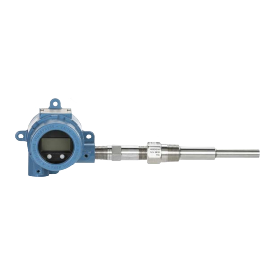
Temperature transmitter
Hide thumbs
Also See for Rosemount 644:
- Reference manual (182 pages) ,
- Quick start manual (48 pages) ,
- Service manual (37 pages)

Related Manuals for Emerson Rosemount 644


Summary of Contents for Emerson Rosemount 644
- Page 1 Reference Manual 00809-0200-4728, Rev SD March 2021 ™ Rosemount 644 Temperature Transmitter ® with HART Protocol...
- Page 2 Using non-nuclear qualified products in applications that require nuclear-qualified hardware or products may cause inaccurate readings. For information on Rosemount nuclear-qualified products, contact your local Emerson Sales Representative. Physical access Unauthorized personnel may potentially cause significant damage to and/or misconfiguration of end users’ equipment. This could be intentional or unintentional and needs to be protected against.
- Page 3 CAUTION Conduit/cable entries The conduit/cable entries in the transmitter housing use a ½–14 NPT thread form. When installing in a hazardous location, use only appropriately listed or Ex certified plugs, glands, or adapters in cable/conduit entries. Unless otherwise marked, the conduit/cable entries in the housing enclosure use a ½–14 NPT form. Only use plugs, adapters, glands, or conduit with a compatible thread form when closing these entries.
-
Page 5: Table Of Contents
Operation and Maintenance..................85 5.1 Overview........................... 85 5.2 Safety messages........................85 5.3 Calibration overview........................87 5.4 Sensor input trim........................88 5.5 Trim the analog output......................91 5.6 Transmitter-sensor matching....................93 5.7 Switching HART Revision......................95 Chapter 6 Troubleshooting...................... 97 6.1 Overview........................... 97 Emerson.com/Rosemount... - Page 6 B.2 Field Communicator Fast Keys....................121 Appendix C Local Operator Interface (LOI)................125 C.1 Number entry.......................... 126 C.2 Text entry..........................127 C.3 Timeout...........................129 C.4 Saving and canceling....................... 129 C.5 LOI menu tree..........................131 C.6 LOI menu tree – extended menu..................... 132 Emerson.com/Rosemount...
-
Page 7: Chapter 1 Introduction
Safety Instrumented Systems (SIS) Certification provides identification, installation, configuration, operation and maintenance, and inspection information for Safety Instrumented Systems as it pertains to the Rosemount 644 Head Mount and Field Mount Temperature Transmitter. Reference Data supplies procedure on how to get the specifications, ordering information, and product certification. - Page 8 The Rosemount 644 Head Mount Transmitter is available in two housing materials (Aluminum and SST) and various housing options that allow for mounting flexibility in a variety of environmental conditions. The Rosemount 644 Field Mount is available in an aluminum housing.
- Page 9 Reference Manual Introduction 00809-0200-4728 March 2021 Table 1-2: Rail Mount HART Revisions Railmount Rosemount 644 Hardware revision Device revision HART revision Emerson.com/Rosemount...
- Page 10 Introduction Reference Manual March 2021 00809-0200-4728 Emerson.com/Rosemount...
-
Page 11: Chapter 2 Configuration
LOI menus are provided for each function below. The LOI is only available on the Rosemount 644 Head Mount and Field Mount designs, and the configuration instructions referencing the interface will not apply to the rail mount form factor. -
Page 12: System Readiness
Not all systems are capable of communicating with HART Revision 7 protocol. This transmitter can be configured for either HART Revision 5 or 7. For instructions on how to change the HART revision of your transmitter, see Switching HART Revision. Emerson.com/Rosemount... -
Page 13: Configuration Methods
To protect against high-energy transients, install the transmitter into a suitable connection head with the integral transient protector, option T1. Refer to the Rosemount 644 Product Data Sheet for more information. - Page 14 Signal loop may be grounded at any point or left ungrounded. • A Field Communicator may be connected at any termination point in the signal loop. The signal loop must have between 250 and 1100 ohms load for communications. • Max torque is 6 in-lb (0.7 N-m). Emerson.com/Rosemount...
- Page 15 DD’s are loaded into the Field Communicator for optimal transmitter performance. Visit Emerson.com/Rosemount to download latest DD library. Turn on the Field Communicator by pressing the ON/OFF key. The Field Communicator will ®...
- Page 16 Entering into the LOI menu effectively disables the ability to write to the device by any other host or configuration tool. Ensure this is communicated to necessary personnel before using the LOI for device configuration. Figure 2-3: LOI Configuration Buttons A. Configuration buttons Table 2-2: LOI Button Operation Button Left SCROLL Right ENTER Emerson.com/Rosemount...
- Page 17 Field Communicator. The values to which the transmitter drives its output in failure mode depend on whether it is configured to standard, NAMUR-compliant, or custom operation. See Rosemount 644 Temperature Transmitter...
-
Page 18: Verify Configuration
Field Communicator are located in Field Communicator Menu Trees and Fast Keys. A Rosemount 644 Device Descriptor (DD) must be installed on the Field Communicator to verify configuration. Verify device configuration using Fast Key sequences in Table 2-3. - Page 19 The default primary variable is Sensor 1. The secondary variable is the transmitter terminal temperature by default. Check or set process variables using the Field Communicator From the HOME screen, enter the Fast Key sequence. Device Dashboard Fast Keys 3, 2, 1 Emerson.com/Rosemount...
-
Page 20: Basic Configuration Of The Transmitter
The transmitter must be configured for certain basic variables in order to be operational. In many cases, all of these variables are pre-configured at the factory. Configuration may be required if the transmitter is not configured or if the configuration variables need revision. Emerson.com/Rosemount... - Page 21 LOI. Figure 2-5: Mapping Variables with LOI VIEW CONFIG CALIBRAT SENSOR CONFIG DAMPING RE-MAP PV UNITS VARIABLE MAP RE-MAP 2V RERANGE RE-MAP 3V LOOP TEST ALM SAT VALUES RE-MAP 4V DISPLAY PASSWORD ..EXTENDED MENU ..EXIT MENU Emerson.com/Rosemount...
- Page 22 The configure sensors method will guide you through the configuration of all necessary settings associated with configuring a sensor including: For a full list of Sensor Types available with the Rosemount 644 Transmitter and their associated levels of accuracy. From the HOME screen, enter the Fast Key sequence.
- Page 23 EXIT MENU EXIT MENU Note Sensor 2 configuration is available only if option code (S) or (D) is ordered. Contact an Emerson representative for information on the temperature sensors, thermowells, and accessory mounting hardware that is available through Emerson. Emerson.com/Rosemount...
- Page 24 1. Right click on the device and select Configure. 2. In the left navigation pane select Manual Setup and select the Sensor 1 or Sensor 2 tab depending on the need. Find the 2-wire offset text field and enter the value. 3. Select Apply when complete. Emerson.com/Rosemount...
- Page 25 Reference Manual Configuration 00809-0200-4728 March 2021 2.6.4 Setting output units The Units can be configured for a number of different parameters in the Rosemount 644 Transmitter. Individual Units can be configured for: • Sensor 1 • Sensor 2 • Terminal temperature •...
-
Page 26: Configure Dual Sensor Options
The list of choices available for Units after the primary menu is dependent on your Sensor configuration settings. Configure dual sensor options Dual-sensor configuration deals with the functions that can be used with a transmitter ordered with Dual Sensor inputs. In the Rosemount 644 Transmitter these functions include: • Differential temperature •... - Page 27 EXIT MENU EXIT MENU EXIT MENU * Available only if option code (S) or (D) is ordered. ** Available only if option codes (S) and (DC) are both ordered, or if option codes (D) and (DC) are both ordered. Emerson.com/Rosemount...
- Page 28 (DC) are both ordered. 2.7.2 Average temperature configuration The Rosemount 644 Transmitter ordered and configured for dual-sensors can output and display the average temperature of any two inputs. Use the following procedures to configure the transmitter to measure the average temperature:...
- Page 29 (via HART ) states that both Sensor 1 and Sensor 2 have failed In the first two scenarios, the 4–20 mA signal is not disrupted and the status available to the control system (via HART) specifies which sensor has failed. Emerson.com/Rosemount...
- Page 30 5. Select Apply when complete. Configure Hot Backup using LOI ™ To configure Hot Backup on the LOI, enable the mode and set the PV values. Reference Figure 2-12 for where to find these in the menu. Emerson.com/Rosemount...
- Page 31 The combination of sensor drift alert and Hot Backup improves sensor diagnostic coverage while maintaining a high level of availability. Refer to the Rosemount 644 FMEDA report for the impact on safety. Emerson.com/Rosemount...
- Page 32 Enabling the drift alert option to WARNING will set a flag (through the HART communications) whenever the maximum acceptable difference between Sensor 1 and Sensor 2 has been exceeded. For the transmitter’s analog signal to go into ALARM when drift alert is detected, select alarm during the configuration process. Emerson.com/Rosemount...
-
Page 33: Configure Device Outputs
2. In the left navigation pane select Manual Setup. 3. On the Analog Output Tab find the Primary Variable Configuration group box. 4. Change the Upper Range Value and Lower Range Value to their desired settings. 5. Select Apply when complete. Emerson.com/Rosemount... - Page 34 5.0 seconds, the transmitter calculates and reports a new reading every 500 milliseconds using the damping equation. At 5.0 seconds, the transmitter outputs 106.3 degrees, or 63 percent of the input change, and the output continues to approach the input curve according to the equation above. Emerson.com/Rosemount...
- Page 35 Intermittent sensor detection. Figure 2-15: Change in Input vs. Change in Output with Damping Set to Five Seconds Damping can be applied to a number of parameters in the Rosemount 644 Transmitter. Variables that can be damped are: • Primary Variable (PV) •...
- Page 36 0.1 mA less than the high alarm max. Rail mount transmitters have a low saturation min of 0.1 mA greater than the low alarm setting, with a minimum of 0.1 mA greater than the low alarm min. Emerson.com/Rosemount...
- Page 37 HOT BACK CONFIG** DRIFT ALERT** ..* Available only if option code (S) or (D) is ordered. ** Available only if option codes (S) and (DC) are both ordered, or if option codes (D) and (DC) are both ordered. Emerson.com/Rosemount...
- Page 38 Min and max 2 • Average temperature • Min and max 3 • First good temperature • Min and max 4 • Differential temperature Reference Figure 2-18 to view the differences between the LCD display and LOI options available with the transmitter. Emerson.com/Rosemount...
- Page 39 On the Display tab there will be a group box with all available variables that can be displayed. 3. Check and uncheck the desired display variables, with a checked box indicating that the variable will be displayed. 4. Select Apply when complete. Emerson.com/Rosemount...
-
Page 40: Inputting Device Information
It has no impact on the operation of the transmitter or the HART-based communicator. The Descriptor variable provides a longer user-defined electronic label to assist with more specific transmitter identification than is available with tag. The Descriptor may be up to Emerson.com/Rosemount... - Page 41 Figure 2-20 to find the tag configuration path in the LOI. Figure 2-20: Configuring the Tag with LOI CALIBRAT VIEW CONFIG DAMPING SENSOR CONFIG VARIABLE MAP UNITS RERANGE ALM SAT VALUES LOOP TEST PASSWORD DISPLAY ..EXTENDED MENU EXIT MENU Emerson.com/Rosemount...
-
Page 42: Configure Measurement Filtering
Reset the device using AMS Device Manager Procedure 1. Right click on the device and select Service Tools. 2. In the left navigation pane select Maintenance. 3. On the Reset/Restore tab select the Processor Reset button. 4. Select Apply when complete. Emerson.com/Rosemount... - Page 43 (100 percent of sensor limits if Intermittent Sensor Detect is OFF). Unless a rapid response rate is necessary, the suggested setting is ON with 0.2 percent threshold. Configure intermittent sensor detect using AMS Device Manager Procedure 1. Right click on the device and select Configure. Emerson.com/Rosemount...
-
Page 44: Diagnostics And Service
2.10.4 Open sensor hold off The open sensor hold off option, at the normal setting, enables the Rosemount 644 Transmitter to be more robust under heavy EMI conditions. This is accomplished by the software having the transmitter perform additional verification of the open sensor status prior to activating the transmitter alarm. - Page 45 Digital loop test is only available in HART Revision 7 mode. Simulate a digital signal using a Field Communicator From the HOME screen, enter the Fast Key sequence. Device Dashboard Fast Keys 3, 5, 2 Emerson.com/Rosemount...
- Page 46 Then a Trigger threshold must be selected, which can be two, three, or four times the baseline resistance, or the default of 5000 ohms. If the thermocouple loop resistance reaches the Trigger Level, a maintenance alert is generated. Emerson.com/Rosemount...
- Page 47 SIMULATE BACK TO MENU EXTENDED MENU HART REV EXIT MENU EXIT MENU HOT BACK CONFIG* DRIFT ALERT* TC DIAG CONFIG MIN MAX TRACK BACK TO MENU EXIT MENU * Available only if option code (S) or (D) is ordered. Emerson.com/Rosemount...
- Page 48 Minimum/maximum tracking diagnostic Minimum and maximum temperature tracking (min/max tracking) when enabled records minimum and maximum temperatures with date and time stamps on Rosemount 644 HART Head Mount and Field Mount Temperature Transmitters. This feature records values for Sensor 1, Sensor 2, Differential, Average, First Good, and Terminal temperatures.
-
Page 49: Establishing Multi-Drop Communication
(1–15) and responds to the commands defined in the HART protocol. A Field Communicator can test, configure, and format a multidropped transmitter the same as in a standard point-to-point installation. Note Multi-drop is not suitable for safety-certified applications and installations. Emerson.com/Rosemount... - Page 50 H. Transmitter Note Rosemount 644 Transmitters are set to address 0 at the factory, allowing them to operate in the standard point-to-point manner with a 4–20 mA output signal. To activate multidrop communication, the transmitter address must be changed to a number between 1 and 15.
-
Page 51: Using The Transmitter With The Hart Tri-Loop
The procedures are to be used when the sensors and transmitters are connected, powered, and functioning properly. Also, Field Communicator must be connected and communicating to the transmitter control loop. For communicator usage instructions, see Verify configuration using the Field Communicator. Emerson.com/Rosemount... - Page 52 Hot Backup To enable the Hot Backup feature of a transmitter with dual-sensor option operating in conjunction with the HART Tri-Loop, ensure that the output units of the sensors are the Emerson.com/Rosemount...
- Page 53 5. Configure the DCS so that TV < –148 °F (–100 °C) or TV > 212 °F (100 °C) indicates a sensor failure and, for example, TV ≤ 26.6 °F (–3 °C) or TV ≥ 37.4 °F (3 °C) indicates a drift alert. See Figure 2-26. Emerson.com/Rosemount...
-
Page 54: Transmitter Security
To enable the write protect feature, perform the following procedures. Configure transmitter security using a Field Communicator From the HOME screen, enter the Fast Key sequence. Write Protect 2, 2, 9, 1 HART Lock 2, 2, 9, 2 LOI Password 2, 2, 9, 3 Emerson.com/Rosemount... - Page 55 1. Right click on the device and select the Configure menu. 2. In the left navigation pane select Manual Setup then select the Security tab. • All three parameters can be configured from this screen. 3. Select Apply when complete. Emerson.com/Rosemount...
- Page 56 Configuration Reference Manual March 2021 00809-0200-4728 Emerson.com/Rosemount...
-
Page 57: Chapter 3 Hardware Installation
Overview The information in this section covers installation considerations for the Rosemount 644 ® Temperature Transmitter with HART Protocol. A Quick Start Guide is shipped with every transmitter to describe recommended mounting and wiring procedures for initial installation. -
Page 58: Considerations
Keep in mind the need for easy access, personnel safety, practical field calibration, and a suitable transmitter environment. Install the transmitter to minimize vibration, shock, and temperature fluctuation. Emerson.com/Rosemount... - Page 59 Special mounting Special mounting hardware is available for mounting a Rosemount 644 Head Mount Transmitter to a DIN rail or assembling a new Rosemount 644 Head Mount to an existing threaded sensor connection head (former option code L1). 3.3.5...
- Page 60 (35 °C [95 °F]) and reduces temperature-effect errors but would probably require extra transmitter support. Gauge the requirements for individual applications along this scale. If a thermowell with lagging is used, the extension length may be reduced by the length of the lagging. Emerson.com/Rosemount...
-
Page 61: Installation Procedures
1. Set the loop to manual (if applicable) and disconnect the power. 2. Remove the housing cover. 3. Set the physical hardware alarm switch to the desired position. H indicates High, L indicates Low. Then reattach the housing cover. See Figure 3-3 for alarm switch location. Emerson.com/Rosemount... - Page 62 If using an LCD Display or LOI, first remove the display by detaching it from the top of the device, set the switch to the desired position and reattach the display. See Figure 3-4 for proper display orientation. Figure 3-4: Display Connection Transmitter Field mount transmitter Emerson.com/Rosemount...
- Page 63 • To a DIN rail using an optional mounting clip. The Rosemount 644 Field Mount installs in a field mount housing, directly mounted on a sensor or apart from a sensor assembly using an optional bracket. The Rosemount 644 Rail Mount attaches directly to a wall or to a DIN rail.
- Page 64 7. Insert the shielded cable leads into the connection head through the conduit entry. 8. Connect the shielded power cable leads to the transmitter power terminals. Avoid contact with sensor leads and sensor connections. Connect and tighten the cable gland. Emerson.com/Rosemount...
- Page 65 March 2021 9. Install and tighten the connection head cover. Enclosure covers must be fully engaged to meet explosion-proof requirements. Head mount transmitter with threaded sensor installation A. Rosemount 644 Transmitter B. Universal junction box C. Threaded style sensor D. Extension E.
- Page 66 9. Install and tighten the universal head cover. Enclosure covers must be fully engaged to meet explosion-proof requirements. Field mount transmitter with threaded sensor installation A. Rosemount 644 Field Mount B. Field mount housing C. Threaded style sensor D. Extension E.
- Page 67 5. Tighten the connection head cover. Enclosure covers must be fully engaged to meet explosion-proof requirements. 6. Run sensor lead wires from the sensor assembly to the transmitter. 7. Verify the transmitter failure mode switch. 8. Attach the sensor wires to the transmitter. Emerson.com/Rosemount...
- Page 68 7. Attach additional sensor lead wires from the connection head to the transmitter. 8. Attach and tighten the connection head cover. Enclosure covers must be fully engaged to meet explosion-proof requirements. 9. Set the transmitter failure mode switch. 10. Attach the sensor wires to the transmitter. Emerson.com/Rosemount...
- Page 69 Between 250 Ω and 1100 Ω if no load resistor. A. Transmitter no. 1 B. Transmitter no. 2 C. R Lead D. Readout or controller no. 1 E. Readout or controller no. 2 F. Backup battery G. To additional transmitters H. DC power supply Emerson.com/Rosemount...
- Page 70 Meter cover with O-ring in place Figure 3-7: Display Connection Transmitter Field mount transmitter A. Rosemount 644 Transmitter A. Rosemount 644 Field Mount B. Mounting screw and springs B. LCD rotation screws C. LCD display C. LCD display D. LCD rotation screws Procedure 1.
- Page 71 Reference Manual Hardware Installation 00809-0200-4728 March 2021 Note Observe the following LCD display temperature limits: • Operating: –40 to 175 °F (–40 to 80 °C) • Storage: –50 to 185 °F (–45 to 85 °C) Emerson.com/Rosemount...
- Page 72 Hardware Installation Reference Manual March 2021 00809-0200-4728 Emerson.com/Rosemount...
-
Page 73: Chapter 4 Electrical Installation
March 2021 Electrical Installation Overview The information in this section covers installation considerations for the Rosemount 644 Temperature Transmitter. A Quick Start Guide is shipped with every transmitter to describe mounting, wiring, and basic hardware installation procedures for initial installation. -
Page 74: Wiring And Powering The Transmitter
The sensor wiring diagram is located on the device’s top label below the terminal screws. Figure 4-1 Sensor wiring for where to find and how to correctly wire all sensor types to the transmitter. Figure 4-1: Wiring Diagram Location Head mount transmitter Field mount transmitter Emerson.com/Rosemount... - Page 75 To ensure a proper sensor connection, anchor the sensor lead wires into the appropriate captive terminals and tighten the screws. Sensor wiring Emerson provides a 4-wire sensors for all single element RTDs. You can use these RTDs in 3-wire configurations by leaving the unneeded leads disconnected and insulated with electrical tape.
- Page 76 See the transient label for indication of “+” and “-” terminal connections. 4. Tighten the terminal screws. When tightening the sensor and power wires, the maximum torque is 6.5 in-lb (0.73 N-m). 5. Reattach and tighten the cover (if applicable). 6. Apply power (12–42 Vdc). Emerson.com/Rosemount...
- Page 77 Instead of the shield carrying the currents away from the transmitter, the currents will now flow through the sensor leads into the transmitter circuitry where it will interfere with the circuit operation. Emerson.com/Rosemount...
- Page 78 If the technique does not eliminate the transmitter alarms, try another technique. If all of the techniques do not eliminate or prevent the transmitter alarms because of high EMI, contact an Emerson representative.
- Page 79 3. Ground shield at the power supply end only. 4. Ensure the sensor shield is electrically isolated from the surrounding grounded fixtures. A. Sensor wires B. Transmitter C. Shield ground point D. 4-20 mA loop Note Connect shields together, electrically isolated from the transmitter. Emerson.com/Rosemount...
- Page 80 3. Do not connect the signal wiring shield to the sensor wiring shield. 4. Ground the signal wiring shield at the power supply end. A. Sensor wires B. Transmitter C. Shield ground point D. 4-20 mA loop Emerson.com/Rosemount...
- Page 81 2. Ensure the sensor wiring and signal wiring shields are electrically isolated from the transmitter housing. 3. Do not connect the signal wiring shield to the sensor wiring shield. 4. Ground signal wiring shield at the power supply end. A. Sensor wires B. Transmitter C. Shield ground point D. 4–20 mA loop Emerson.com/Rosemount...
- Page 82 Note that the resistance of intrinsic safety barriers, if used, must be included. Note Permanent damage to the transmitter could result if the voltage drops below 12.0 Vdc at the power terminals, when changing transmitter configuration parameters. Emerson.com/Rosemount...
- Page 83 Reference Manual Electrical Installation 00809-0200-4728 March 2021 Figure 4-5: Load Limits Maximum Load = 40.8 × (Supply voltage - 12.0) A. Load (ohms) B. Supply voltage (V C. Operating region Emerson.com/Rosemount...
- Page 84 Electrical Installation Reference Manual March 2021 00809-0200-4728 Emerson.com/Rosemount...
-
Page 85: Operation And Maintenance
00809-0200-4728 March 2021 Operation and Maintenance Overview This section contains information on calibrating Rosemount 644 Temperature Transmitter. Field Communicator, AMS Device Manager, and Local Operator Interface (LOI) instructions are given to perform all functions. Safety messages Read this manual before working with the product. For personal and system safety, and for optimum product performance, ensure you thoroughly understand the contents before installing, using, or maintaining this product. - Page 86 Using non-nuclear qualified products in applications that require nuclear-qualified hardware or products may cause inaccurate readings. For information on Rosemount nuclear-qualified products, contact your local Emerson Sales Representative. Physical access Unauthorized personnel may potentially cause significant damage to and/or misconfiguration of end users’...
-
Page 87: Calibration Overview
One or more of the trim functions may be used when calibrating. The trim functions are as follows: • Sensor input trim • Transmitter-sensor matching • Output trim • Output scaled trim Emerson.com/Rosemount... -
Page 88: Sensor Input Trim
5.4.2 Application: Linear offset and slope correction (two- point trim) Procedure 1. Connect sensor to transmitter. Place sensor in bath at low range point. 2. Enter known bath temperature using the Field Communicator. 3. Repeat at high range point. Emerson.com/Rosemount... - Page 89 Figure 5-2: Trimming the Sensor with the LOI CALIBRAT SENSOR 1 CALIB VIEW CONFIG DAMPING SENSOR 2 CALIB* SENSOR CONFIG VARIABLE MAP ANALOG TRIM UNITS FACTORY RECALL RERANGE ALM SAT VALUES BACK TO MENU LOOP TEST PASSWORD EXIT MENU DISPLAY ..EXTENDED MENU EXIT MENU Emerson.com/Rosemount...
- Page 90 Disable this mode before putting the transmitter back into the process to set the transmitter back to pulsating current. “Active Calibrator Mode” is volatile and will automatically be disabled when a master reset is performed (through HART) or when the power is cycled. Emerson.com/Rosemount...
-
Page 91: Trim The Analog Output
Field Communicator 5.5.2 Analog output trim The analog output trim allows the transmitter’s conversion of the input signal to a 4–20 mA output to be altered (Figure 5-4). Adjust the analog output signal at regular intervals to maintain measurement precision. Emerson.com/Rosemount... - Page 92 4 and 20 mA (2–10 volts, for example). To perform a scaled D/A trim, connect an accurate reference meter to the transmitter and trim the output signal to scale as outlined in the Trim the analog output procedure. Emerson.com/Rosemount...
-
Page 93: Transmitter-Sensor Matching
Use Transmitter-Sensor Matching to enhance the temperature measurement accuracy of the system and if you have a sensor with Callendar-Van Dusen constants. When ordered from Emerson, sensors with Callendar-Van Dusen constants are NIST-traceable. The transmitter accepts Callendar-Van Dusen constants from a calibrated RTD schedule and generates a special custom curve to match that specific sensor Resistance vs. - Page 94 Table 5-1: Standard RTD vs. RTD with Matched CVD Constants with Standard Transmitter Accuracy System accuracy comparison at 150 °C using a PT 100 (α=0.00385) RTD with a span of 0 to 200 °C Standard RTD Matched RTD Rosemount 644 ±0.15 °C Rosemount 644 ±0.15 °C Standard RTD ±1.05 °C Matched RTD ±0.18 °C...
-
Page 95: Switching Hart Revision
HART Revision 7 and HART Revision 5 from a generic menu in any HART compliant configuration tool. Procedure Locate “Message” field. a) To change to HART Revision 5, Enter: HART5 in the message field. b) To change to HART Revision 7, Enter: HART7 in the message field. Emerson.com/Rosemount... - Page 96 CALIBRAT ZERO TRIM DAMPING UNITS VARIABLE MAP RERANGE LOOP TEST ALM SAT VALUES DISPLAY PASSWORD EXTENDED MENU SIMULATE HART REV 7 EXIT MENU HART REV HART REV 5 ..BACK TO MENU BACK TO MENU MAIN MENU EXIT MENU Emerson.com/Rosemount...
-
Page 97: Chapter 6 Troubleshooting
All connection head covers must be fully engaged to meet explosion-proof requirements. Process leaks Process leaks could result in death or serious injury. Do not remove the thermowell while in operation. Install and tighten thermowells and sensors before applying pressure. Emerson.com/Rosemount... - Page 98 Using non-nuclear qualified products in applications that require nuclear-qualified hardware or products may cause inaccurate readings. For information on Rosemount nuclear-qualified products, contact your local Emerson Sales Representative. Physical access Unauthorized personnel may potentially cause significant damage to and/or misconfiguration of end users’...
-
Page 99: 4-20 Ma/Hart Output
(improved), or reference Field Communicator for previous versions. Contact Emerson Customer Central for assistance. 2. Check for a minimum of 250 ohms resistance between the power supply and Field Communicator connection. 3. Check for adequate voltage to the transmitter. If a Field Communicator is connected and 250 ohms resistance is properly in the loop, then the transmitter requires a minimum of 12.0 V at the terminals to operate (over... - Page 100 Potential cause Sensor element Recommended actions 1. Connect a Field Communicator and enter the transmitter test mode to isolate a sensor failure. 2. Check the process variable to see if it is out of range. Potential cause Loop wiring Emerson.com/Rosemount...
-
Page 101: Diagnostic Messages
Essential electronics in the device have failed. The transmitter may have experienced an electronics failure while attempting to store information. Recommended actions 1. Restart the transmitter. 2. If condition persists, replace the transmitter. Contact the nearest Emerson Field Service Center if necessary. Emerson.com/Rosemount... - Page 102 Terminal temperature failure ALARM TERM ALARM FAIL Potential cause The terminal temperature is outside the internal RTD’s specified operating range. Recommended actions Verify the ambient temperature is within the device specified operating range using the terminal temperature information button. Emerson.com/Rosemount...
- Page 103 HOT BU SNSR 1 HOT BU FAIL Potential cause Sensor 1 has failed (open or shorted) and Sensor 2 is now the primary process variable output. Recommended actions 1. Replace Sensor 1 at you earliest convenience. 2. Reset Hot Backup feature in the device software. Emerson.com/Rosemount...
- Page 104 3. Verify the integrity of the sensor itself. Harsh process conditions may cause long-term sensor failures. Calibration error Potential cause The value entered for the user trim point was not acceptable. Recommended actions Re-trim the device, ensure the user entered calibration points are close to the applied calibration temperature. Emerson.com/Rosemount...
- Page 105 Terminal Temperature Information Button. 6.4.3 Other LCD display messages LCD is not displaying correctly or at all Rosemount 644 HART 7 on screen Potential cause The display may not be functioning or it may be stuck on Home screen. Recommended actions If the meter does not appear to function, ensure the transmitter is configured for the meter option you desire.
-
Page 106: Return Of Materials
3. Perform a device reset. Return of materials To expedite the return process in North America, call the Emerson National Response Center toll-free at 800-654-7768. This center, available 24 hours a day, will assist you with any needed information or materials. -
Page 107: Safety Instrumented Systems (Sis) Certification
SIL 3 for systematic integrity Safety certified identification All Rosemount 644 HART Head Mount and Field Mount Transmitters must be identified as safety certified before installing into a SIS. To identify a safety-certified transmitter, ensure the device satisfies the requirements... -
Page 108: Configuration
Alarm and saturation levels DCS or safety logic solver should be configured to match transmitter configuration. Figure identifies the three alarm levels available and their operations values. Figure 7-1: Alarm Levels (1)(2) Rosemount alarm level (1)(2) Namur alarm level Emerson.com/Rosemount... -
Page 109: Operation And Maintenance
The partial proof test 1 consists of a power cycle plus reasonability checks of the transmitter output. Reference the FMEDA Report for percent of possible DU failures in the device. FMEDA report can be found at Rosemount 644 Temperature Transmitter product page. - Page 110 Visual inspection Not required. Special tools Not required. Product repair The Rosemount 644 is repairable by replacement only. All failures detected by the transmitter diagnostics or by the proof-test must be reported. Feedback can be submitted electronically at Emerson.com/Rosemount/Contact-Us. Emerson.com/Rosemount...
-
Page 111: Specifications
Reference Manual Safety Instrumented Systems (SIS) Certification 00809-0200-4728 March 2021 Specifications The Rosemount 644 Transmitter must be operated in accordance to the functional and performance specifications provided in the Product Data Sheet. 7.6.1 Failure rate data The report is available at the Rosemount 644 Temperature Transmitter product page. - Page 112 Safety Instrumented Systems (SIS) Certification Reference Manual March 2021 00809-0200-4728 Emerson.com/Rosemount...
-
Page 113: Appendix A Reference Data
Reference Data 00809-0200-4728 March 2021 Reference Data Product certifications To view current Rosemount 644 Temperature Transmitter product certification, follow these steps: Procedure 1. Go to Emerson.com/Rosemount/Rosemount-644. 2. Scroll as needed to the green menu bar and click Documents & Drawings. -
Page 114: Ams Terms
Launches a method to recalculate the Baseline value (which may resistance: take several seconds). TC diagnostic This field will read either enabled or disabled indicating when the mode sensor 1or thermocouple degradation diagnostic is on or off for that sensor. Emerson.com/Rosemount... -
Page 115: Appendix B Field Communicator Menu Trees And Fast Keys
2 High Saturation 3 Low Saturation 4 High Alarm 5 Low Alarm 6 Software Write Protect 7 Lock Status 8 Password Protection Options Ordered 1 Dual Sensor Option 2 Hot BU and Sensor Drift 3 T/C Diag & Min/Max Emerson.com/Rosemount... - Page 116 6 Fourth Variable 6 Variable Mapping 7 Config Adt’l Messages Security Variable Mapping 1 Software Write Protect 1 Primary Variable 2 HART Lock 2 Second Variable 3 Local Operator Interface* 3 Third Variable 4 Fourth Variable 5 Re-Map Variables Emerson.com/Rosemount...
- Page 117 Sensor Calibration 1 Calibrate Sensors 2 Restore Facotry Cal 3 Sensor 1 Lower Cal 4 Sensor 1 Upper Cal 5 Sensor 2 Lower Cal 6 Sensor 2 Upper Cal 7 Active Calibrator Analog Calibration 1 Analog Trim 2 Scaled Trim Emerson.com/Rosemount...
- Page 118 2 High Saturation 3 Low Saturation 4 High Alarm 5 Low Alarm 6 Software Write Protect 7 Lock Status 8 Password Protection Options Ordered 1 Dual Sensor Option 2 Hot BU and Sensor Drift 3 T/C Diag & Min/Max Emerson.com/Rosemount...
- Page 119 6 Fourth Variable 6 Variable Mapping 7 Config Adt’l Messages Security Variable Mapping 1 Software Write Protect 1 Primary Variable 2 HART Lock 2 Second Variable 3 Local Operator Interface* 3 Third Variable 4 Fourth Variable 5 Re-Map Variables Emerson.com/Rosemount...
- Page 120 Sensor Calibration 1 Calibrate Sensors 2 Restore Facotry Cal 3 Sensor 1 Lower Cal 4 Sensor 1 Upper Cal 5 Sensor 2 Lower Cal 6 Sensor 2 Upper Cal 7 Active Calibrator Analog Calibration 1 Analog Trim 2 Scaled Trim Emerson.com/Rosemount...
-
Page 121: Field Communicator Fast Keys
Open Sensor Hold off 2, 2, 7, 3 2, 2, 7, 3 Percent Range 2, 2, 5, 2 2, 2, 5, 2 Sensor 1 Configuration 2, 1, 1 2, 1, 1 Sensor 2 Configuration 2, 1, 1 2, 1, 1 Emerson.com/Rosemount... - Page 122 1, 3, 3, 3, 4 Calibration 1, 2, 2 Callendar-Van Dusen 1, 3, 2, 1 Configuration 1, 3 D/A Trim 1, 2, 2, 2 Damping Values 1, 1, 10 Date 1, 3, 4, 2 Descriptor 1, 3, 4, 3 Emerson.com/Rosemount...
- Page 123 1, 3, 2, 1, 2 Sensor Serial Number 1, 3, 2, 1, 4 Sensor 1 Trim 1, 2, 2, 1 Sensor 1 Trim- Factory 1, 2, 2, 1, 2 Sensor Type 1, 3, 2, 1, 1 Software Revision 1, 4, 1 Emerson.com/Rosemount...
- Page 124 1, 2, 1 URV (Upper Range Value) 1, 1, 7 USL (Upper Sensor Limit) 1, 1, 9 Variable Mapping 1, 3, 1 Variable Re-Map 1, 3, 1, 5 Write Protect 1, 2, 3 2-Wire Offset 1, 3, 2, 1, 2, 1 Emerson.com/Rosemount...
-
Page 125: Appendix C Local Operator Interface (Loi)
Entering into the LOI menu effectively disables the ability to write to the device by any other host or configuration tool. Ensure this is communicated to necessary personnel before using the LOI for device configuration. Figure C-1: LOI Configuration Buttons A. Configuration buttons Table C-1: LOI Button Operation Button Left SCROLL Right ENTER Emerson.com/Rosemount... -
Page 126: Number Entry
Press scroll to navigate through the 00001122 numbers until the “1”, is on the screen. Press the enter button to select the “1” for 00001122 the sixth digit. The seventh digit from the left will now be blinking. Emerson.com/Rosemount... -
Page 127: Text Entry
Menu scrolling Simply hold down the left button after it brings you to the next menu item, each of the proceeding menus will be shown one after another while the button is pressed down. Emerson.com/Rosemount... - Page 128 B A C K T O M E N U M e n u E X I T B A C K T O M E N U M E N U E X I T M E N U Emerson.com/Rosemount...
-
Page 129: Timeout
“SAVE?” to ask the user if they want to save the information just entered. You can select the cancel function (choose NO) or the save function (choose YES). After the save function is selected, “SAVED” shall appear on the screen. Emerson.com/Rosemount... - Page 130 Damping, and Calibration values. If you do not want to re-enter the value and desire to continue canceling, select the NO option when prompted. Figure C-6: Canceling 005.0000 005.0000 005.0000 S A v e ? S A v e D S E C RE-- E N T E R ? Emerson.com/Rosemount...
-
Page 131: Loi Menu Tree
MINMAX 3 (on/off) MINMAX 4 (on/off) BACK TO MENU EXIT MENU EXTENDED MENU CALIBRAT DAMPING VARIABLE MAP ALM SAT VALUES PASSWORD SIMULATE HART REV HOT BACK CONFIG DRIFT ALERT TC DIAG CONFIG MIN MAX TRACK BACK TO MENU EXIT MENU Emerson.com/Rosemount... -
Page 132: Loi Menu Tree - Extended Menu
TRIGGER CONFIG CONFIG SNSR 2 BACK TO MENU TRIGGER VIEW EXIT MENU SNSR OHM VIEW BASELINE RE-SET MIN MAX TRACK BASELINE VIEW MIN-MAX MODE BACK TO MENU PARAM CONFIG EXIT MENU VIEW VALUES RESET VALUES BACK TO MENU EXIT MENU Emerson.com/Rosemount... - Page 133 Reference Manual 00809-0200-4728 March 2021 Emerson.com/Rosemount...
- Page 134 2021 Emerson. All rights reserved. Emerson Terms and Conditions of Sale are available upon request. The Emerson logo is a trademark and service mark of Emerson Electric Co. Rosemount is a mark of one of the Emerson family of companies. All other marks are the property...
Need help?
Do you have a question about the Rosemount 644 and is the answer not in the manual?
Questions and answers