Table of Contents
Advertisement
Instruction Manual
Form 5596
July 2005
4200 Series Electronic Position
Transmitters
Contents
. . . . . . . . . . . . . . . . . . . . . . . . . . . . . . .
. . . . . . . . . . . . . . . . . . . . . . . . .
. . . . . . . . . . . . . . . . . . . . . . . . . . . . . .
. . . . . . . . . . . . . . . . . . . . . . . . . . . .
. . . . . . . . . . . . . . . . . . . . . . . . . . . . . . . .
. . . . . . . . . . . . . . . . . . . . . . . . . . . . . . . .
. . . . . . . . . . . . . . . . . . . . . . . . . . . . .
. . . . . . . . . . . . . . . . . . . . . . . . . .
. . . . . . . . . . . . . . . . . . . . . . . .
. . . . . . . . . . . . . . . . . . . . . . . . . . . . . . .
. . . . . . . . . . . . . . . . . . . . . . . . .
. . . . . . . . . . . . . . . . . . . . . . . . . . .
. . . . . . . . . . . . . . . . . . . . . . . . . . .
. . . . . . . . . . . . . . . . . . . . . . . . . . .
. . . . . . . . . . . . . . . . . . . . . . .
. . . . . . . . . . . . . . . . . . . . . . . . . . . . .
www.Fisher.com
. . . . . . . . . . . . . . . . . . . . . .
. . . . . . . . . . . . . . . . . . .
. . . . . . . . . . .
. . . . . . . . . . .
. . . . . . . .
. . . . . . . .
. . . . . . . . . . . . . . . . . . . . .
. . . . . . . . . . . . . . . . .
. . . . . . . . . . . . . . . . . .
. . . . . . . . . . . . . . . . . . . . .
. . . . . . . . . . . . . . . . . . . . .
. . . . . . . . . . . . . . . . .
. .
. . . . . . . . . .
. . . . . . . . . .
. . . . . . . . . . . . .
. . . . . . . . . . . . . . . . . . . . .
. . . . . . . . . . . . . . . . . . . .
. . . . . . . . . . . . . .
. . . . . . . . . . . . . . . . . . . . . .
. . . . . . . . . . . . . . . . . .
4200 Series Transmitters
1
1
2
2
4
6
7
7
7
8
9
9
9
9
12
14
16
16
W4273-1
SLIDING-STEM
16
ACTUATOR MOUNTING
16
17
17
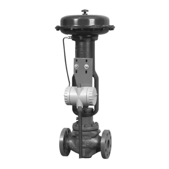
Figure 1. Typical 4200 Series Position Transmitters
17
17
. . . . . . . . . . . . . . . . . . . . . . . . . . . . . . . .
19
19
19
19
Introduction
20
20
Scope of Manual
21
21
This instruction manual provides installation,
21
operating, calibration, maintenance, and parts
22
ordering information for the 4200 Series electronic
23
position transmitters (figure 1). Refer to separate
23
instruction manuals for information on the actuator
23
and valve.
W4274-1
ROTARY
ACTUATOR MOUNTING
. . . . . . . . . . . . . . . . . . . . . . . . . . . .
. . . . . . . . . .
26
27
40
Advertisement
Table of Contents

Related Manuals for Emerson Fisher 4200 Series


Summary of Contents for Emerson Fisher 4200 Series
-
Page 1: Table Of Contents
Instruction Manual Form 5596 4200 Series Transmitters July 2005 4200 Series Electronic Position Transmitters Contents Introduction ....... Scope of Manual . -
Page 2: Description
OPERATING your Fisher sales office. REGION Note Neither Emerson , Emerson Process Management, Fisher, nor any of their affiliated entities assumes MAXIMUM TRANSMITTER responsibility for the selection, use TERMINAL VOLTAGE and maintenance of any product. - Page 3 Instruction Manual Form 5596 4200 Series Transmitters July 2005 Table 1. Specifications Available Configurations Operating Influences See table 2 Ambient Temperature : For a 56_C (100_F) change in normal operating conditions, maximum zero shift is ±0.5%; maximum span shift is Input Signal ±0.75% of span Source: Single potentiometer is standard or a...
-
Page 4: Educational Services
Educational Services For information on available courses for 4200 Series electronic position transmitters, as well as a variety of other products, contact: Emerson Process Management Educational Services, Registration P.O. Box 190; 301 S. 1st Ave. Marshalltown, IA 50158−2823 Phone: 800−338−8158 or Phone: 641−754−3771... - Page 5 Instruction Manual Form 5596 4200 Series Transmitters July 2005 Table 5. Hazardous Area Classifications for North America CERTIFICATION MODEL/ TEMPERATURE ENCLOSURE CERTIFICATION OBTAINED ENTITY RATING BODY TYPE CODE RATING (Intrinsic Safety) Class/Division t 71°C) 4211, 4221 − − − TC3 (T SClass I,II,III Division 1 GP A,B,C,D,E,F,G per drawing 20B6503 4210, 4211,...
-
Page 6: Installation
Instruction Manual Form 5596 4200 Series Transmitters July 2005 PORT TRANSMITTER 1/2-INCH NPT FIELD WIRING COMPARTMENT (2 PLACES) COMPARTMENT (4.00) (6.25) (2.00) 5/16-18UNC 13 DEEP (0.53) (2.00) (4.00) (2 PLACES) BOTTOM VIEW (1.38) 6 (0.25) DIA. (3.00) POTENTIOMETER SHAFT (2.62) (2.62) (0.81) ALLOW 254 mm (10 INCHES) -
Page 7: Mechanical Connections
Instruction Manual Form 5596 4200 Series Transmitters July 2005 removing the covers to perform maintenance and to (keys 23, 24, and 22) using the two tapped holes in make the wiring connections. Figure 3 also shows the side of the actuator yoke. the basic transmitter outline dimensions. -
Page 8: Long Stroke Sliding-Stem Actuator Mounting Type 585C And 470-16
Instruction Manual Form 5596 4200 Series Transmitters July 2005 screws (key 32) holding the transmitter to the 4. Attach the cable transducer housing (key 100A) mounting plate (key 21). to the mounting plate (key 63) using cap screws (key 103) and hex nuts (key 104). 5. -
Page 9: Long Stroke Sliding-Stem Actuator Mounting Type 585Cls And 490
Instruction Manual Form 5596 4200 Series Transmitters July 2005 Long Stroke Sliding-Stem Type 585CLS 8. Mount the mounting plate (key 100C) to the transmitter using cap screws (key 105). and 490 Actuator Mounting, Types 4220, 4221, and 4222 9. Verify that the actuator is still in the mid-stroke position. - Page 10 Instruction Manual Form 5596 4200 Series Transmitters July 2005 determine the power supply requirements. For units (−) terminal of the power supply to the (R) without position switches, the 24 volts dc can be terminal on TB3. Also connect a wire from the (−) provided by the receiving device or an external terminal on the power supply to the negative (−) supply.
- Page 11 Instruction Manual Form 5596 4200 Series Transmitters July 2005 TRANSMITTER FIELD WIRING RELAY RETURN FIELD WIRING COMPARTMENT FIELD CIRCUIT PRINTED POWER WIRING BOARD SUPPLY − EARTH GROUND DEVICE RECEIVING 4 TO 20 MA DC SIGNAL − POSITION SWITCH DEVICE FIELD WIRING RECEIVING LO GROUNDING TERMINAL...
-
Page 12: Potentiometer Alignment
Instruction Manual Form 5596 4200 Series Transmitters July 2005 Potentiometer Alignment 3. Loosen the appropriate set screw connecting the potentiometer shaft to the linkage: a. For sliding stem applications, loosen the set CAUTION screw (key 26, figure 15) in the operating arm (key 30) on the potentiometer shaft. - Page 13 Instruction Manual Form 5596 4200 Series Transmitters July 2005 SPAN LOW POSITION ADJUSTMENT SWITCH (R2) ADJUSTMENT (R6) HIGH POSITION SWITCH DEADBAND ZERO ADJUSTMENT (R4) ADJUSTMENT (R1) JUMPER W3 LOW POSITION SWITCH DEADBAND ADJUSTMENT (R5) JUMPER W1 JUMPER W2 HIGH POSITION SWITCH ADJUSTMENT (R3) FOR TYPE 4210, 4215, OR 4220 TRANSMITTERS WITH POSITION SWITCHES...
-
Page 14: Direct Or Reverse Action
Instruction Manual Form 5596 4200 Series Transmitters July 2005 FIELD WIRING FEEDTHROUGH TRANSMITTER TRANSMITTER FIELD CIRCUIT PRINTED COMPARTMENT PORT PRINTED WIRING COMPARTMENT WIRING BOARD BOARD FILTER BROWN WIRES FROM GROUNDING ORANGE RFI FILTER TERMINALS POTENTIOMETER O-RINGS SHAFT END VIEW CUTAWAY SIDE VIEW END VIEW FOR TYPE 4210, 4215, OR 4220 TRANSMITTER WITH POSITION SWITCHES AND FOR TYPE 4212 OR 4222 POSITION SWITCHES WITHOUT THE TRANSMITTER... - Page 15 Instruction Manual Form 5596 4200 Series Transmitters July 2005 FOR ROTARY ACTUATORS Transmitter Transmitter Actuator Stem Input Potentiometer Type Actuator Style Set Position Switch Current Output, Action Travel Rotation Milliampere Down Direct Direct Down 4210 4210 Down Reverse Reverse Down Down Direct Direct...
-
Page 16: Operating Information
Instruction Manual Form 5596 4200 Series Transmitters July 2005 Arrange wires on the terminal block (TB1) for either from relays K1 and K2 (figures 4 and 9). The high direct or reverse action to match the application position switch circuit output controls relay K1 requirements;... -
Page 17: Calibration
Instruction Manual Form 5596 4200 Series Transmitters July 2005 blocks (TB1 and TB2) in the field wiring Test Connections to the Field Wiring compartment. Refer to the Calibration section for the Compartment test setup. During calibration setup the transmitter as shown in figure 8. - Page 18 Instruction Manual Form 5596 4200 Series Transmitters July 2005 VIEW A (SEE VIEW A) TO RFI FILTERS J1 FROM RFI FILTERS + 24 VOLT DC POWER SUPPLY FIELD WIRING TRANSMITTER COMPARTMENT COMPARTMENT NOTES: CONNECT DVM TO TEST POINTS AS DIRECTED BY CALIBRATION AND MAINTENANCE PROCEDURES.
-
Page 19: High And Low Position Switch Adjustment
Instruction Manual Form 5596 4200 Series Transmitters July 2005 High and Low Position Switch Note Adjustment The potentiometers are 25 turn trimpots with a slip clutch. To set these potentiometers at their maximum counterclockwise position, Note turn them 25 or more turns in the counterclockwise direction. -
Page 20: Setting The Low Position Switch Deadband
Instruction Manual Form 5596 4200 Series Transmitters July 2005 TRANSMITTER 24 VOLT DC POWER SUPPLY FIELD CIRCUIT TRANSMITTER PRINTED WIRING PRINTED WIRING − BOARD BOARD TRANSMITTER CIRCUIT DEVICE RECEIVING 4 TO 20 MA DC SIGNAL − MECHANICAL CONNECTION SWITCHING DEVICE RELAY TO DEVICE CIRCUIT... -
Page 21: Principle Of Operation
Instruction Manual Form 5596 4200 Series Transmitters July 2005 position switches, turn the high position switch element for the position switch circuit input. On an potentiometer (HIGH, R3) fully clockwise, and turn instrument with position switches only, the single the low position switch potentiometer (LOW, R6) element potentiometer is used for the position switch fully counterclockwise. -
Page 22: Maintenance
Instruction Manual Form 5596 4200 Series Transmitters July 2005 NOTES: RELAYS K1 AND K2 ARE SHOWN IN THE DE-ENERGIZED POSITION. (TRIPPED POSITION) 29A6206-C / DOC Figure 10. Schematic Diagram for the Field Printed Wiring Board Maintenance WARNING On an explosion-proof instrument, WARNING remove the electrical power before removing the instrument covers in a... -
Page 23: Troubleshooting Procedures
Instruction Manual Form 5596 4200 Series Transmitters July 2005 Troubleshooting Procedures c. If the potentiometer voltage is present but the transmitter output current does not change linearly as the position of the potentiometer Transmitter Circuit changes, replace the transmitter printed wiring board, or return the transmitter to the factory for Note repair. - Page 24 Instruction Manual Form 5596 4200 Series Transmitters July 2005 FOR TYPE 4211 OR 4221 TRANSMITTER WITHOUT POSITION SWITCHES FOR TYPE 4210, 4215, OR 4220 TRANSMITTER FOR TYPE 4212 OR 4222 POSITION SWITCHES 39A7236-E WITH POSITION SWITCHES WITHOUT TRANSMITTER 39A6156-F 39A6156-F A3504-2 / IL A3497-2 / IL Figure 11.
- Page 25 Instruction Manual Form 5596 4200 Series Transmitters July 2005 Table 8. Jumper Selection POSITION TRANSMITTER WITH SWITCHES AND SINGLE TRANSMITTER WITH SWITCHES AND JUMPER* SWITCH POTENTIOMETER 4210, 4220 DUAL POTENTIOMETER 4215 4212 Not Installed Installed Not Installed Not Installed Installed Not Installed Installed Not Installed...
-
Page 26: Parts Ordering
6. Remove the pot/bushing assembly (key 3) from the housing (key 1). Note 7. When installing the pot/bushing assembly (key 3) Neither Emerson, Emerson Process in the transmitter housing, apply lubricant (key 50) to Management, Fisher, nor any of their the bushing threads. -
Page 27: Parts List
Instruction Manual Form 5596 4200 Series Transmitters July 2005 APPLY LUBRICANT OR SEALANT NOTES: ON 4212, 4222, USE KEY 35 INSTEAD OF KEY 19 AT THE “−”FEEDTHROUGH POSITION, OMIT KEY 10 49A7893-L / IL Figure 13. Housing Assembly for Type 4210, 4215, or 4220 Transmitter with Position Switches and for Type 4212 or 4222 Position Switches without Transmitter Description Part Number... - Page 28 Instruction Manual Form 5596 4200 Series Transmitters July 2005 APPLY LUBRICANT OR SEALANT 49A7891-K / IL Figure 14. Housing Assembly for Type 4211 or 4221 Transmitter without Position Switches Description Part Number Description Part Number Stem Mounting Bracket, zn pl steel Size 30, 40, 45, 63, 64 16A0430X012 Mounting Parts for Sliding Stem...
- Page 29 Instruction Manual Form 5596 4200 Series Transmitters July 2005 PICK-UP PIN TRAVEL, CONNECTION mm (Inch) NUMBER OPERATING HEX NUT Up to 54 (2.125) max Up to 105 (4.125) max PICK-UP PIN ACTUATOR YOKE ACTUATOR STEM CONNECTION TRANSFER LEVER ASSEMBLY HEX CAP SCREW PICK-UP PIN IN PICKUP PIN...
- Page 30 Instruction Manual Form 5596 4200 Series Transmitters July 2005 Description Part Number Description Part Number Washer, pl steel (2 req’d) Stem Washer, pl steel (2 req’d) (cont’d) Size 30 thru 40 1D716228982 Size 70 thru 87 w/MO Size 45 thru 100 1B865928982 76 mm (4 inch) travel 1H723125072...
- Page 31 Instruction Manual Form 5596 4200 Series Transmitters July 2005 STEM BRACKET VIEW INDENT 1 INDENT 2 INDENT 3 INDENT 4 INDENT MARK TRAVEL INDENT NUMBER INCHES 0.75 1.125 FOR SIZES 25 AND 50 39A7636-D / DOC STEM BRACKET VIEW INDENT 1 INDENT 2 INDENT 3 INDENT 4...
- Page 32 Instruction Manual Form 5596 4200 Series Transmitters July 2005 37B4775-A / DOC Figure 17. Typical Transmitter Mounting on Type 585C or 585CR Actuator...
- Page 33 Instruction Manual Form 5596 4200 Series Transmitters July 2005 APPLY LUBRICANT 40B7441−A / DOC Figure 18. Typical Transmitter Mounting on Type 1250 or 1250R Actuator Description Part Number Description Part Number Stem Bracket, steel Size 225, 450 30B6736X012 Parts for Mounting the Transmitter on Size 675 30B7385X012 Type 1250 or 1250R Actuator (figure 18)
- Page 34 Instruction Manual Form 5596 4200 Series Transmitters July 2005 APPLY LUBRICANT 49A7766-B / DOC Figure 19. Typical Transmitter Mounting on Type 1051, 1052, or 1061 Actuator Description Part Number Description Part Number Mounting Parts for Rotary Actuators Cap Screw, pl steel (2 req’d) 1C631224052 Anti-seize (not furnished with transmitter) Parts for Mounting the Transmitter on...
- Page 35 Instruction Manual Form 5596 4200 Series Transmitters July 2005 NOTE: FIELD MOUNTING PARTS APPLY LUBRICANT APPLY LUBRICANT 34A8843-B / DOC 34A8841-A / DOC Figure 21. Typical Transmitter Mounting on Type 1063, 1064, 1065, 1066, or 1066SR Actuator Parts for Mounting the Transmitter on Figure 20.
- Page 36 Instruction Manual Form 5596 4200 Series Transmitters July 2005 SECTION A−A TRANSDUCER ASSEMBLY GE13433 GE16564 Figure 22. Typical Transmitter Mounting on a Type 470-16 Actuator (585C with Travel Greater than 4-inches)
- Page 37 Instruction Manual Form 5596 4200 Series Transmitters July 2005 Mounting Parts for Long Stroke Sliding Description Part Number Stem Actuators Mounting Plate, stainless steel Yoke boss 5H, Parts for Mounting the Transmitter on Cylinder size 127 to 254 mm (5 to 10 inches), Max travel Type 470-16 Actuator (585C with travel 305 mm (12 inches) and...
- Page 38 Instruction Manual Form 5596 4200 Series Transmitters July 2005 Description Part Number Description Part Number Cap Screw, stainless steel, (4 req’d) Lockwasher, stainless steel 1A3291X0012 Yoke boss 5H, Washer, pl steel (6 req’d), (not shown) 1F230328992 Cylinder size 127 to 254 mm (5 to 10 inches), Transducer Assy Max travel 305 mm (12 inches) and...
- Page 39 Instruction Manual Form 5596 4200 Series Transmitters July 2005 SECTION A−A 77 86 GE13430 TRANSDUCER ASSEMBLY GE16563 Figure 23. Typical Transmitter Mounting on a Type 490 (585CLS) Actuator...
-
Page 40: Loop Schematics And Nameplates
Instruction Manual Form 5596 4200 Series Transmitters July 2005 Loop Schematics and Nameplates This section includes loop schematics required for wiring of intrinsically safe installations. It also contains the approvals nameplates. If you have any questions, contact your Fisher sales office. 20B6503-A Sheet 1 of 2 Figure 24. - Page 41 Instruction Manual Form 5596 4200 Series Transmitters July 2005 20B6503-A Sheet 2 of 2 Figure 24. CSA Schematics (continued) TYPES 4211 AND 4221 TYPES 4210, 4212, 4215, 4220, AND 4222 INTRINSICALLY SAFE EXPLOSION PROOF Figure 25. CSA Approval Nameplates...
- Page 42 Instruction Manual Form 5596 4200 Series Transmitters July 2005 20B6408-E Figure 26. FM Schematics TYPES 4210, 4211, 4212, 4215, 4220, TYPES 4211 AND 4221 4221 AND 4222 INTRINSICALLY SAFE EXPLOSION PROOF Figure 27. FM Approval Nameplates...
- Page 43 Instruction Manual Form 5596 4200 Series Transmitters July 2005 SPECIFIC CONDITIONS FOR SAFE USE STHIS EQUIPMENT IS INTRINSICALLY SAFE AND CAN BE USED IN POTENTIALLY EXPLOSIVE ATMOSPHERES. STHE APPARATUS MUST ONLY BE CONNECTED TO A CERTIFIED ASSOCIATED INTRINSICALLY SAFE EQUIPMENT AND THIS COMBINATION TYPES 4211 AND 4221 MUST BE COMPATIBLE AS REGARDS INTRINSIC SAFETY RULES.
- Page 44 Fisher is a mark owned by Fisher Controls International LLC, a member of the Emerson Process Management business division of Emerson Electric Co. Emerson and the Emerson logo are trademarks and service marks of Emerson Electric Co. All other marks are the property of their respective owners.
Need help?
Do you have a question about the Fisher 4200 Series and is the answer not in the manual?
Questions and answers