
Related Manuals for Svantek SV 803


Summary of Contents for Svantek SV 803
- Page 1 USER MANUAL SV 803 VIBRATION MONITORING TERMINAL NEED HELP? Warsaw, 2023-04-21 Copyright © 2023 SVANTEK. Rev. 1.03 All rights reserved. SCAN OR CLICK HERE TO CONTACT US Air-Met Scientific www.airmet.com.au...
- Page 2 To download the most up to date user's manual please visit Svantek website at www.svantek.com. This user manual presents the SV 803 firmware revision 1.03. and the Assistant Pro software revision 1.0.5. WEEE Notice: Do not throw the device away with the unsorted municipal waste at the end of its life.
-
Page 3: Important Notes Before Use
In this case the warranty for the Li-ion battery is void. ✓ If SV 803 is to be stored for a long period, it is recommended that the battery is charged to 60% capacity. The battery should be charged at least once every 6 months. - Page 4 SV 803 User Manual SAFETY AND ENVIRONMENTAL PROTECTION MARKING OF THE UNIT Marking on the Unit Explanation This product meets consumer safety, health or environmental requirements This product meets EU consumer safety, health or environmental requirements Do not throw into standard municipal waste containers. The user is...
- Page 5 Axes are assigned to the channels of the SV 803: the X-axis is assigned to channel 1, the Y-axis is assigned to channel 2 and the Z-axis is assigned to channel 3.
-
Page 6: Table Of Contents
Keypad and LEDs ....................... 11 Instrument control ......................11 Waterproof housing ......................12 Battery removal and charging ..................13 Replacing geophones ......................15 Optional accessories for SV 803 ..................17 2.6.1 External power adapter ....................17 2.6.2 Solar panel ........................17 OPERATING SV 803 .................. - Page 7 SV 803 User Manual 4.4.2 Live View ........................29 4.4.3 Cloud .......................... 33 4.4.4 Files list ........................34 4.4.5 Instrument settings ..................... 34 4.4.6 Restoring factory settings ................... 35 Assistant Pro auxiliary functions and settings ............... 36 Instrument settings ......................38 Measurement settings –...
- Page 8 Transportation and storage ....................90 Cleaning ..........................90 Troubleshooting ......................... 90 SV 803 TECHNICAL DATA ................91 APPENDIX D. DEFINITIONS AND FORMULAE OF MEASURED VALUES ... 94 Basic terms and definitions ..................94 Definitions and formulas of measuring results ............95...
-
Page 9: Introduction
(VDV). One of the biggest advantages of the SV 803 is its energy efficiency. It can run on the battery up to 180 days. The instrument can be powered by the internal battery or an external DC power supply, such as a solar panel. -
Page 10: Accessories Included
Torque screwdriver SA 83 32 GB memory card SA 85 Key to unfasten geophone plugs Note: SV 803 is delivered in protective packaging. Please keep it for use when transporting your equipment. 1.3 A CCESSORIES AVAILABLE SV 110 Hand-held vibration calibrator (80Hz & 160Hz) including carrying case... -
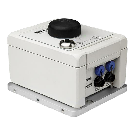
Page 11: 803 Description
2.2 I NSTRUMENT CONTROL SV 803 can be controlled via the Bluetooth connection, 4G connection or USB. Each type of connection is supported by special software: Assistant Pro mobile device application (see Chapter 4) that supports the Bluetooth connection, SvanNET web-service that supports the 4G connection to the Internet (see Chapter 5) -
Page 12: Waterproof Housing
If the instrument is to be used for continuous monitoring, choose a service provider that guarantees good reception at the measurement point. Note: Make sure the SIM card has the PIN code disabled before inserting it into the SV 803. To open the housing, loosen the clamp and then using the torque screwdriver, unscrew the two screws under the clamp that ensure the watertightness of the SV 803. -
Page 13: Battery Removal And Charging
The battery must be removed from the instrument housing to be charged using the SV 83 mains charger. Note: If SV 803 is not supplied via the WEIPU5 connector, it is necessary to turn off SV 803 before removing the battery. - Page 14 After inserting the battery, tighten the screw (not too tight) to secure the battery in the housing. The battery has: 4. contacts for connecting the battery to the SV 803 circuit, 5. six green LEDs indicating the state of charge, 6.
-
Page 15: Replacing Geophones
SV 803 User Manual 2.5 R EPLACING GEOPHONES Note: Before removing the geophones, the SV 803 must be switched off. Geophones must be placed in the geophone block according to the SV 803 position. If SV 803 is positioned horizontally (usually on the ground), the central geophone must be of the vertical type. - Page 16 SV 803 User Manual To remove the geophone block: • unscrew the four screws that fix the base of the geophone block to the housing of the geophone. (1) and • unscrew the left-down long screw on the central geophone (2).
-
Page 17: Optional Accessories For Sv 803
SV 803 User Manual 2.6 O SV 803 PTIONAL ACCESSORIES FOR 2.6.1 External power adapter SB 274 is waterproof single output switching power supply which is characterised by: • Universal AC input / Full range (90 ~ 305V AC) •... -
Page 18: Operating Sv 803
In this case, the warranty for the Li-Ion battery is void. Note: If SV 803 is to be stored for a long period, it is recommended that the battery is charged to 60% capacity. The battery should be charged at least once every 6 months. -
Page 19: Establishing 4G Connection
Internet provider uses a different APN. In this case, the APN must be entered manually using the Assistant Pro application (see Chapter 4.6.6) or the SvanPC++ program (see Chapter 6.4). Note: If the connection to SvanNET fails, contact your local distributor or the SVANTEK support team. -
Page 20: Mounting The Instrument
If the instrument was automatically switched off due to a discharged battery, it will switch on automatically when a charged battery is inserted. In other cases, you should turn on SV 803 manually by pressing two keys at the same time (for appx. -
Page 21: Measurement Run And Data Storage
When SV 803 uses the 4G connection to SvanNET, it can periodically transfer data files to the Cloud in automatic mode (and, if configured, delete transferred files). The programmable periodic connection mode is used to prolong the battery life. -
Page 22: Overload Indication
SV 803 should be calibrated by an authorised laboratory. Note: SV 803 is sensitive to shock. If it is dropped on a hard surface, it must be recalibrated. Note: The recommended factory calibration interval is 12 months to ensure continued accuracy and compliance with international specifications. -
Page 23: System Check
YSTEM HECK SV 803 has a special mechanism for testing the measurement chain, so called System Check, by triggering an electronic pulse and then evaluating the response of the sensor signal. If the System Check finds an error, the warning about this is displayed in the Assistant Pro application and in the SvanNET web service. -
Page 24: Application For Mobile Devices - Assistant Pro
Note: The geophone positions in the geophone pack should match the SV 803 position (on the ground or on the wall) – see Chapter 2.5. If the geophones do not match the SV 803 position, the instrument icon will start flashing red. -
Page 25: Description Of The Status Icons
SV 803 User Manual Note: You cannot have access to the instruments controlled by other users who are simultaneously running Assistant Pro applications on other mobile devices. The first time you pair the instrument, the application will try to use the default PIN code (1234). If it does not match, you will be prompted to enter the PIN code. -
Page 26: Controlling The Instrument
SV 803 User Manual Bluetooth – connected. The instrument is measuring. The instrument is not measuring. 4G modem – not connected. 4G modem – connected to the Internet. 4G modem – connected to SvanNET. 4.4 C ONTROLLING THE INSTRUMENT The visible instruments appear on the Assistant Pro screen as a bar that can be expanded by tapping it. Once expanded, the instrument panel displays the device's battery and memory status, as well as the values of some predefined readings. - Page 27 SV 803 User Manual Below are screens after tapping function icons: Live View, Cloud, Files and Setup. You can access these and other functions by long tapping on the instrument bar. The pop-up menu allows you to: • check the Status of the instrument, •...
-
Page 28: Auxiliary Commands
SV 803 User Manual 4.4.1 Auxiliary commands When you tap Status, the Status dialogue box will tell you if the measurement and communication configurations are correct. If not, the anomalies are listed. When you tap Identify, the three LEDs on the front of the instrument will flash red four times to indicate which unit you are currently working with. -
Page 29: Live View
SV 803 User Manual 4.4.2 Live View From the Live View screen, you can start or stop the measurement and set a marker - a note during the measurement. The measurement results are displayed in two sections which you can adjust by scrolling through the presentation views. - Page 30 SV 803 User Manual Note: The FFT or 1/3 octave spectra views depend on the selected standard – see Chapter 4.6.1.1. FFT spectra are displayed for most standards based on the PPV and its dominant frequency analysis. 1/3 octave spectra are displayed for the User standard based on the 1/3 octave analysis.
- Page 31 SV 803 User Manual Tap the marker icon to open the Create Marker dialogue box, where you can activate the marker to which you can assign the photo, video, or audio recording. Tap Title to enter the marker name. Tap Comment to enter the comment text.
- Page 32 SV 803 User Manual When you tap , you can: • see the Product overview, • see the User manual, • Identify instrument, Chapter 4.4.1, • perform Systen check, In-situ check and Calibration. To return to the “Stations in range” screen, tap the...
-
Page 33: Cloud
SV 803 User Manual 4.4.3 Cloud Tap Cloud, to open the Remote Connection screen. -
Page 34: Files List
SV 803 User Manual 4.4.4 Files list The Files section displays the list of files created by the instrument on the instrument’s memory card. You can tap on each file to download it to your mobile device (Get). Once the file has been downloaded, you can share it. -
Page 35: Restoring Factory Settings
SV 803 User Manual After configuring the settings, you can save them to the mobile device catalogue (Save), load them to the instrument as the current settings (Apply), or save and load them simultaneously (Save & Apply). When you save settings, a new setup file is created in the dedicated application’s directory on your mobile device, but the current instrument settings are not changed. -
Page 36: Assistant Pro Auxiliary Functions And Settings
SV 803 User Manual 4.5 A SSISTANT RO AUXILIARY FUNCTIONS AND SETTINGS By tapping , you can open SvanNET in your mobile device, configure Assistant Pro settings, share the log file with Android applications and view, edit and share previously created markers, get quick tips, read the terms and conditions and privacy policy and exit the application. - Page 37 SV 803 User Manual If your mobile device has an OLED or AMOLED screen, you can turn on Dark mode to save the power. Quick tips give you a quick overview of the Assistant Pro.
-
Page 38: Instrument Settings
SV 803 User Manual 4.6 I NSTRUMENT SETTINGS The configuration menu (Settings) contains the following sections: • Measurement – to configure the measurement parameters, • Logger – to configure data storage in a logger file, • Recording – to configure signal recording to a WAV file, •... - Page 39 SV 803 User Manual Standard settings – Application 4.6.1.1 In the Standard field, you can select the application method/standard: PPV, BS-7385-2, DIN-4150-3, KBfmax, 22/09/1994, 23/07/1986/1, 23/07/1986/2, IN-1226-A, IN-1226-B, IN-1226-C, IEST VC or User. The content of the Application sub-section depends on the selected standard and may include the following settings: •...
- Page 40 SV 803 User Manual The table below describes the application methods/standards used: Standard / Reference Filtering Method Method DIN-4150-3 Part 3: Effects of vibration DIN 80 Measurement of unweighted PPV on structures bandpass without frequency analysis DIN 315 bandpass BS-7385-2...
- Page 41 SV 803 User Manual If you don’t find the application method in the Standard list, you can customise your own parameters for a criterion curve based on the FFT or 1/3 octave velocity spectra (RMS and Peak) and create your own criterion curve.
- Page 42 SV 803 User Manual Human vibration measurements – Human Vibration 4.6.1.2 The instrument can simultaneously measure vibration acceleration, allowing VDV to measured measurement with a different recording step to PPV. The instrument has built-in weighting filters according to ISO 2631-1 and ISO 2631- 2 and BS 6472-1.
-
Page 43: Configuring Data Storage - Logger
SV 803 User Manual 4.6.2 Configuring data storage – Logger The Logger section allows you to configure the way in which the measurement results are stored in files. The instrument performs measurements of velocity vibration (according to the selected standard) and acceleration vibration (if activated in the Human Vibration) for measurement periods (called Steps) that can be set. - Page 44 SV 803 User Manual In other cases, the logging is done in separate files and the logging in a new file is synchronised to every quarter of the RTC (Sync. to full 15m), or to every half an hour of the RTC (Sync. to full 30m), or to every hour of the RTC (Sync.
- Page 45 SV 803 User Manual The Storage Results section allows you to select the results for logging in the logger file: • Velocity Results: PPV, P-P (Peak-to-Peak), Max, RMS, RRMS (Rolling RMS), VEC (Vector PPV), (Overload time), • spectrum results (Spectrum...
-
Page 46: Configuring Alarms - Alarm
SV 803 User Manual 4.6.3 Configuring alarms – Alarm SV 803 can generate SMS and e-mail notifications as well as visual and audible alarms when a specific event occurs. You can configure alarms when either some PPV, RMS etc. values or some standard’s criterion curves (e.g., DIN 4150-3) or user’s criterion curves based on FFT, or... - Page 47 SV 803 User Manual Configuring events – Event 4.6.3.2 The Event x sub-section allows you to configure the event. When the event is active (On), you can define its Name, enable specific alarms, set the trigger source, threshold level(s) time...
- Page 48 SV 803 User Manual The settings of some parameters depend on the selected standard/method. As the Source of the event trigger, you can select: System, PPV, RMS, RRMS (Rolling RMS), Vector PPV which will be compared with the threshold level(s) or select the building type criterion curve (Curve) to be checked for exceedance.
- Page 49 SV 803 User Manual The Days of Week item allows you to select the days of the week, and the Start (hh:mm) and Stop (hh:mm) items allow you to define the time frame in which alarms are generated. If System is selected as the Source, the System...
- Page 50 SV 803 User Manual Lamp Connected – the alarm lamp is connected; the alarm is generated after the Lamp Disconnected • alarm • Cover Open – opening of the instrument lid; the alarm is generated when the lid is opened •...
- Page 51 SV 803 User Manual Threshold X/Y/Z for RMS or RRMS Event trigger level for each or PPV trigger axis. For triggering, it is sufficient to exceed the value of one axis Threshold for Vector PPV Event trigger level for trigger...
-
Page 52: System Checking - Calibration
SV 803 User Manual 4.6.4 System checking – Calibration SV 803 has a special mechanism for testing the measurement chain, called the system check, by triggering an electronic pulse and then evaluating the response of the sensor signal. The Calibration section allows you to enable the system check and set the time and days of the week when the instrument will be performing the system check. -
Page 53: Configuring Remote Communication - Communication
SV 803 User Manual Configuring internal GPS – GPS 4.6.5.2 The GPS item allows you to switch GPS on/off, select the Time Zone, switch RTC synchronization on/off synchronisation time. If RTC Synchronization is On, the Stop to sync at time of day... - Page 54 SV 803 User Manual Configuring 4G modem – Wireless transfer 4.6.6.2 In the Wireless transfer sub-section, you can switch Off the 4G modem, or select mode (Modem): Continuous Periodically active. In continuous mode, the modem is active all the time. However, this mode is...
-
Page 55: Internet Service Platform - Svannet
By default, SV 803 is configured for the periodic connection to SvanNET. When the station is turned on, the 4G modem works for two hours and then goes into sleep mode. If you want to wake up the 4G modem, press the key on the SV 803 keypad and after a while SV 803 will be connected to SvanNET again. -
Page 56: Remote Communication Service - Stations
SV 803 User Manual SvanNET includes the standard function - Remote Communication Services, which is available to all SvanNET users, and the optional extension - Automatic Monitoring Services, which is offered via a licence. Remote Communication Services maintain a remote connection to the monitoring devices and the service includes status alarms (e.g., battery, memory), remote access to device settings and measurement files stored... - Page 57 SV 803 User Manual Project status: this icon appears when the station is involved in the project. Clicking on this icon displays the project name and a link to it. Alert status: blue - everything is OK, red – an irregular event is happening.
-
Page 58: Status View
SV 803 User Manual 5.2.1 STATUS view From the STATUS view you can check status of the station and:. • switch the modem mode (Power Saving Mode Override Switch), • enable e-mail notification when the station is reconnected to SvanNET (Notify when station comes online), •... - Page 59 SV 803 User Manual 2. click OK and new condition will be displayed in the CONDITIONS area. 3. click the E-mail button to enter/edit e-mail recipients. 4. click the Assign button to refer alarm to the station(s). 5. Made selections are displayed in the ACTIONS and MEASUREMENT POINTS areas.
-
Page 60: Certificates Dialog Box
SV 803 User Manual The Status sources have the following meanings: • Mains Trigger Value: Off – an alarm is generated when the system detects loss of power supply Trigger Value: On – an alarm is generated when the system detects the occurence of power supply •... -
Page 61: Log Views
SV 803 User Manual 5.2.3 LOG views There are three station logs, that record system events, connections, and data transfer: • Status log that records the type of power source and charge level, free memory space, GSM signal quality, system check history and GPS information. -
Page 62: Web Interface View
SV 803 User Manual • Data transfer log that registers history of data transfers (uploads). In the top line you can: refresh the log, select the period of records to be viewed, and select the period for viewing the data transfer: Monthly, Weekly, Daily or Hourly. -
Page 63: Status View
SV 803 User Manual 5.2.4.1 Live data view Live data view displays the map with the instrument location and results measured in three channels, updated every second: 1. Instantaneous velocity results measured/averaged over a 1-second period; and 2. Current averaged velocity results in the three channels measured/averaged over the INTERGRATION TIME in the range [1s ÷... - Page 64 SV 803 User Manual 5.2.5.1 Configuration views The Configuration view consists of several sections that allow configuring measurement parameters (Measurement setup), measurement results storage (Storage), files export in CSV format (CSV export), the measured signal recording in WAV format (Wave recording), station alarms based on events (Event trigger), periodic system check (Calibration), auxiliary parameters (Auxiliary) and the firmware upgrade (Firmware upgrade).
- Page 65 SV 803 User Manual There are two ways to create a curve – using a table or a graph. Both ways complementary. First select the curve you wish to create or modify (Curve 1, Curve 2 or Curve 3). If you want to use a table, enter the...
- Page 66 SV 803 User Manual If you want to change the position of the previously created point, you can change its coordinates using either the table or the graph. You can change the Velocity units from µm/s to mm/s by clicking on the Units button.
- Page 67 SV 803 User Manual Note: All measurement results and waveforms are stored in files with automatically defined names. You can define both file names manually via the Assistant Pro or SvanPC++ interface (see Chapters 4.6.2.1, 4.6.2.2 and 6.3.4). The CSV export section allows you to export results in the CSV (Comma Separated Values) format.
- Page 68 SV 803 User Manual In the Wave recording section, you can: 1. set the Mode of the recording: Disable, Continuous (signals are recorded from the measurement start till the measurement end) or On event (signals are recorded during the event period), 2.
- Page 69 SV 803 User Manual To add a new event, click on +Add event. The new Event section will appear with the CONDITIONS and Actions fields. To edit the event name, click on After editing the event name confirm it by clicking on...
- Page 70 SV 803 User Manual Threshold trigger condition The Threshold type trigger activates the event when the measured value (Source) exceeds above the threshold. In the Source list, select the result to be compared with the threshold: PPV, RMS, RRMS (rolling RMS), Vector or Curve.
- Page 71 SV 803 User Manual System trigger condition The System trigger type activates the event when some of the system conditions occur. You can select some or all of the conditions presented in the SYSTEM CONDITION configuration box (see description in Chapter 4.6.3.2).
- Page 72 SV 803 User Manual After the event occurs, actions are performed while the event is active, at its start or at its end depending on the action type. The Alarm lamp action triggers an alarm signal on the EXTERNAL INTERFACE connector to which an alarm device can be connected (e.g., alarm lamp).
- Page 73 SV 803 User Manual When confirmed (OK), the pop-up boxes close, and the selections are displayed in the lines of the corresponding Actions buttons. Address book The ADDRESS BOOK pop-up box appears in the SMS and E-mail alarm actions pop-up boxes after you click on +Add recipients.
- Page 74 In the Firmware upgrade section, you can upload new firmware to the instrument’s SD-card and perform the upgrade process remotely. Before upgrading, it is essential to download the correct firmware file from the SVANTEK website to your PC. To upgrade the firmware: 1.
-
Page 75: Storage View
SV 803 User Manual 5.2.6 STORAGE view The Storage view presents a list of files stored in the instrument’s SD card memory. The list contains only files from a single directory on the memory card and it initially displays the contents of the current working directory. -
Page 76: Automatic Monitoring Services - Projects
WYSIWYG (What You See Is What You Get) functionality. Configuring panels, formatting and creating reports is described in detail in the SvanNET User Manual. This manual only describes parts related to the operation of SV 803. 5.3.1 Viewing time-history of measured results – Charts panel The Charts panel presents time-histories of some results. -
Page 77: Viewing Events - Events Panel
SV 803 User Manual If you point the mouse at the plot, you can read the Pointer coordinates in the legend box. Click on the plot and read the Cursor coordinates in the legend box. 5.3.2 Viewing events – Events panel The Events panel displays the list of events (left pane) and details of selected events (right pane). - Page 78 SV 803 User Manual...
-
Page 79: Printing Reports
SV 803 User Manual By clicking on the icon in the Events panel, you can change the Panel title and customise the display of events details: 1. Select the time range for viewing events (Select time range): Default period (Default time range), Last hour, Last day, Last month, Last year, Last x period, Fixed period. -
Page 80: Data Post-Processing - Svanpc
The SvanPC++ software for the PC enables configuring instrument settings and provides also wide spectrum of data post-processing and reporting functionalities. SV 803 needs to be connected to the computer running SvanPC++ either by the USB cable or the internet. In the last case SvanPC++ should be supplemented with the Remote Communication module. -
Page 81: Downloading/Uploading Files
SV 803 User Manual 6.3.1 Downloading/uploading files Arrows in between are used to download files from the instrument to the PC and upload files from the PC to the instrument. PC files Instrument files 6.3.2 Opening files Double click the file name to open the Viewer module that enables different tools for data viewing. This module... -
Page 82: Changing Working Directory
The Setup file editor is available in two modes: Standard and Extended. The settings available in the Setup file editor correspond to those available via the SV 803 instrument’s interface. Setup file editor in the Standard mode allows for viewing the settings that are most likely to be modified, presented in a simple and intuitive way. - Page 83 Parameters In the Extended mode, all the settings of SV 803 are visible and available for editing. The list of settings, located at the left-hand side of the window, can be displayed in a tree view or a list view. You can switch the view using the buttons located in the lower part of the window.
-
Page 84: Configuring Wireless Connection
The internet connection can be configured via SV 803 instrument wizard. For this: 1. In the SV 803 instrument wizard dialog box, click the Remote Connection using SvanNET button. 2. In the Remote Connection Wizard dialog box, type the Station name, Station description and APN of the mobile operator. -
Page 85: Building Vibration View
Rxx, where xx is a number, and extension WAV. One Rxx file includes waveform signal recorded for one detected event during the period set in SV 803 as a PreTrigger + Duration + Post Trigger. Note: While retrieving data from SV 803 remember to retrieve all files created during a measurement. -
Page 86: Fft Approach
6.5.2 FFT approach In case of the FFT approach, the Building vibration view presents a table with SV 803 settings and data for the time history, events or alarms and Criterion curves with measurement results for three axes (X, Y, Z) as a points. - Page 87 SV 803 User Manual If you press the Events list button located next to the Alarm/Event/Time history selector, the new Alarms view will appear. This view presents the table with all events detected. You can display two tables, Building vibration and Alarms side by side. If you change the row in the Alarms table...
- Page 88 SV 803 User Manual To create a report, press the Send to MS Word button at the left side of the view Toolbar...
-
Page 89: Maintenance
7.1 K EEPING DRY INSIDE Keep SV 803 dry inside If suspicion of any moisture inside the housing, find the cause, dry it out. If sent to repair after damage from moisture, please remove the battery to minimize damage. 7.2 E... -
Page 90: Preservation Of The Internal Battery
Note: If SV 803 is planned to be stored for a long period of time, it is recommended to charge its battery to 60% capacity. The battery should be charged at least once per 6 months. -
Page 91: 803 Technical Data
SV 803 User Manual SV 803 TECHNICAL DATA Parameter Value/ Description Physical data Dimensions 163 x 128 x 115 mm (without accessories) Weight Approx. 3 kg including battery Approx. 3 kg including battery and mounting plate Leakproof classification IP 67 according to EN 60529 (1997) + A1 (2000) Working ambient -20C do +50C (Ambient air temperature, without direct sunlight). - Page 92 SV 803 User Manual External DC input voltage: 5 V to 28 V External DC power 15 V (waterproof) supply SB 274 Solar panel (option) OCV voltage up to 28 V Note: Size and power of the panel depend on the climate of the area where the station operates.
- Page 93 SV 803 User Manual • Position Accuracy (horizontal): < 2.5 m CEP (autonomous), • Tracking Sensitivity: -163dBm • Time accuracy: <1µs (directly depends on position deviation) Measurement characteristics Standards DIN 45699-1:2020-06; ISO 4866:2010, Class 1; IEC 61260:2014, Class 1 Meter Mode...
-
Page 94: Appendix D. Definitions And Formulae Of Measured Values
SV 803 User Manual APPENDIX D. DEFINITIONS AND FORMULAE OF MEASURED VALUES �� Basic terms and definitions current time period of the measurement in seconds. reference duration of 28 800 seconds (8 hours) �� exponential time constant in seconds with the time-weighting 125 ms. -
Page 95: Definitions And Formulas Of Measuring Results
SV 803 User Manual Definitions and formulas of measuring results The instrument calculates the vibration measurement results for two profiles, one for the velocity vibration and another for the acceleration vibration. The calculation flow diagram for one profile is presented below:... - Page 96 SV 803 User Manual ( �� ) ���� ������ = ( ∫ �� 2 ⁄ �� ���� �� Root mean square result acceleration signal for the axis X, Y or Z that is frequency- and time-weighted and averaged for a stated time interval T.
Need help?
Do you have a question about the SV 803 and is the answer not in the manual?
Questions and answers