Samson 3731-3 Mounting And Operating Instructions
3731 series
electropneumatic ex d
with hart communication
Hide thumbs
Also See for 3731-3:
- Mounting and operating instructions (116 pages) ,
- Operating instructions manual (132 pages) ,
- Configuration manual (28 pages)

Subscribe to Our Youtube Channel
Related Manuals for Samson 3731-3


Summary of Contents for Samson 3731-3
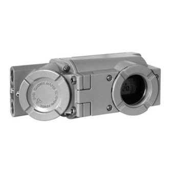
- Page 1 Series 3731 Type 3731-3 Electropneumatic Ex d Positioner ® with HART communication Fig. 1 · Type 3731-3 Mounting and Operating Instructions EB 8387-3 EN Firmware version 1.61 EB + CD Edition May 2017...
- Page 2 Definitions of the signal words used in these instructions DANGER! NOTICE indicates a hazardous situation which, if not indicates a property damage message. avoided, will result in death or serious injury. Note: Supplementary explanations, WARNING! information and tips indicates a hazardous situation which, if not avoided, could result in death or serious injury.
-
Page 3: Table Of Contents
Contents Contents Important safety instructions ..... . 6 Article code ......7 Design and principle of operation. - Page 4 Contents 7.5.1 Initialization based on MAX maximum range ... . . 51 7.5.2 Initialization based on NOM nominal range ....52 7.5.3 Initialization based on MAN manually selected range .
- Page 5 Modifications to positioner firmware Modifications to positioner firmware compared to the previous version 1.41 (old) 1.42 (new) After performing a reset to default values, the allocation of the closing position AIR TO OPEN (AtO) /AIR TO CLOSE (AtC) is not reset to the default setting. The setting is kept.
-
Page 6: Important Safety Instructions
Important safety instructions Important safety instructions For your own safety, follow these instructions concerning the mounting, start up and opera- tion of the positioner: The positioner is to be mounted, started up or operated only by trained and experienced personnel familiar with the product. According to these Mounting and Operating Instructions, trained personnel refers to individuals who are able to judge the work they are assigned to and recognize possible dangers due to their specialized training, their knowledge and experience as... -
Page 7: Article Code
Article code Article code x x x x x x x 0 0 x 1 x 0 0 0 Positioner Type 3731 - 3 ® With LCD, autotune, HART communication Explosion protection ATEX: II 2G Ex d IIC T6, T5, T4 Gb; II 2G Ex de IIC T6, T5, T4 Gb; II 2D Ex tb IIIC T80°C DB IP 66 Class I, Div. -
Page 8: Design And Principle Of Operation
Design and principle of operation variable y) is produced for the pneumatic Design and principle of actuator. operation The positioner basically consists of an elec- The electropneumatic Ex d positioner is trical travel sensor system (2), an analog i/p mounted on pneumatic control valves. It is converter (6) with downstream air capacity used to assign the valve stem position (con- booster (7) and the electronic unit with a... -
Page 9: Additional Equipment
Position transmitter accessories: The position transmitter (13) is a two-wire Direct attachment to SAMSON transmitter and issues the travel sensor sig- Type 3277 Actuator: section 4.1 nal as a 4 to 20 mA signal processed by the Attachment to actuators acc. -
Page 10: Communication
Connection to terminals A-B: Binary input vice. for DC voltage signals The device-specific module for Type 3731-3 Connection to terminals B-C: Contact input can be downloaded free of charge from the for an external contact SAMSON website (Services >... - Page 11 Design and principle of operation Technical data Type 3731-3 Ex d Positioner (technical data in test certificates additionally apply for explosion-protected devices) Rated travel Adjustable Direct attachment to Type 3277: 3.6 to 30 mm Attachment acc. to IEC 60534-6 (NAMUR): 3.6 to 300 mm Attachment to rotary actuators (VDI/VDE 3845): 24°...
-
Page 12: Technical Data
Design and principle of operation Type 3731-3 Ex d Positioner (technical data in test certificates additionally apply for explosion-protected devices) At ∆p = 6 bar: 8.5 m ³/h · At ∆p = 1.4 bar: 3.0 m to fill actuator ³/h · K = 0.09... - Page 13 Design and principle of operation Additional equipment Optional binary output, software limit switch, galvanically isolated Connection: Optionally NAMUR EN 60947-5-6 or PLC, configurable as a limit switch or fault alarm output Signal status Terminals B-C Terminals A-B Switching output AC/DC (PLC) ≥...
- Page 14 Design and principle of operation Summary of explosion-protection certificates Type Certificate Type of protection/comments 3731 EC-Type Number PTB 11 ATEX 1014 X II 2G Ex d IIC T6,T5,T4 Gb; Examination II 2G Ex de IIC T6,T5,T4 Gb; Date 2012-07-26 Certificate II 2D Ex tb IIIC T80°C DB IP66 Number RU C-DE-GB08.B.00697...
-
Page 15: Attachment To The Control Valve - Mounting Parts And Accessories
Direct attachment to SAMSON Type 3277 Actuator The positioner is standard equipped with the Attachment to actuators according to lever M (pin position 35). - Page 16 [cm²] [mm] Min. Travel Max. 25.0 120/175/240/350 35.0 355/700/750 10.0 50.0 Attachment according to IEC 60534-6 (NAMUR) SAMSON valves/Type 3271 Actuator Adjustment range at positioner Required Assigned Other valves/actuators Actuator size Rated travel lever pin position [cm²] [mm] min. Travel max.
-
Page 17: Direct Attachment
Attachment to the control valve – Mounting parts and accessories Direct attachment Align the marking of the switchover plate (9) to the corresponding symbol 4.1.1 Type 3277-5 Actuator and mount the plate on the actuator yoke. Refer to Table 1 on page 30 for required If applicable, mount pressure gauge mounting parts and accessories. - Page 18 Attachment to the control valve – Mounting parts and accessories it in the hole for pin position 25 and screw tight. Insert formed seal (15) into the groove of the positioner housing, pressing the four retaining rings over the housing screws and both fittings into the hous- ing recesses.
- Page 19 Attachment to the control valve – Mounting parts and accessories Lever Symbols Switchover plate (9) Disk spring Actuator stem Follower pin extends Follower clamp Screw plug Left attachment Right attachment Stopper Connecting plate for G ¼ Seal rings Actuator stem Pressure gauge bracket retracts Press.
-
Page 20: Type 3277 Actuator
Attachment to the control valve – Mounting parts and accessories 4.1.2 Type 3277 Actuator the lever (1) until it engages into place. Place positioner on the cover plate (10) Refer to Table 2 on page 31 for the required and fasten it using three fixing screws. mounting parts and accessories. - Page 21 Attachment to the control valve – Mounting parts and accessories Connection block Lever 12.1 Screw 1.1 Nut 12.2 Stopper or connection for 1.2 Disk spring external piping Follower pin 10 14 Switch plate Follower clamp Gasket Cover plate G ¼ Formed seal 11.1 Cover...
-
Page 22: Attachment According To Iec 60534-6 (Namur)
Attachment to the control valve – Mounting parts and accessories Mount cover (11) on the other side. Mount NAMUR bracket (10) to the con- Make sure that the vent plug (11.1) trol valve as follows: points to the back when the control –... - Page 23 Attachment to the control valve – Mounting parts and accessories Attachment to Attachment to rod-type yoke NAMUR rib Rods with 20 to 35 mm Ø Lever 1.1 Nut Disk spring Follower pin Follower plate Additional bracket for 3.1 Follower plate actuators with 2800 cm²...
-
Page 24: Attachment To Type 3510 Micro-Flow Valve
Attachment to the control valve – Mounting parts and accessories 6.2 Screw the long follower pin (2) in- (11.1) directly into the holes on the cluded in the mounting kit in the yoke. pin position of the required lever Fasten the bracket (10) to the hex bar (1) assigned in the table. - Page 25 Attachment to the control valve – Mounting parts and accessories Lever Disk spring Follower pin 11.1 Follower plate Connecting plate Seal rings Pressure gauge bracket Pressure gauge mounting kit Stem connector Bracket 12.1 Screws Bracket 10.1 Screw Hex bar 11.1 Screws 12.1 Screws...
-
Page 26: Attachment To Rotary Actuators
(11) underneath, if (accessories order no.1400-6964/item necessary. no. 0390-1424) into the signal pres- For SAMSON Type 3278 and VETEC sure output of the positioner (or the out- S160 Rotary Actuator, screw the put of the pressure gauge bracket or adapter (5) onto the free end of the connecting plate). - Page 27 4.3 Adhesive label Actuator shaft or adapter 5.1 Adapter 10.1 10.1 SAMSON Type 3278 Attachment acc. to VDI/VDE 3845 VETEC S160, VETEC R (Sept. 2010) level 1, size AA1 to AA4 (see section 12.1) Fig. 9 · Attachment to rotary actuators...
-
Page 28: Reversing Amplifier For Double-Acting Actuators
Remove the rubber seal (1.4). positioner must be fitted with a reversing Insert the gasket (1.2) into the recess of amplifier, e.g. the SAMSON Type 3710 Re- the reversing amplifier and push both versing Amplifier (see Mounting and Oper- the hollowed special screws (1.1) into ating Instructions EB 8392 EN). - Page 29 Attachment to the control valve – Mounting parts and accessories From the positioner Output 38 Supply 9 Control signals to the actuator Reversing amplifier 1.1 Special screws 1.2 Gasket 1.3 Special nuts 1.4 Rubber seal 1.5 Sealing plug 1.6 Filter Fig.
-
Page 30: Required Mounting Parts And Accessories
Attachment to the control valve – Mounting parts and accessories Required mounting parts and accessories Order no. Table 1 · Direct attachment to Type 3277-5 (Fig. 4) Mounting parts For actuators with 120 cm² effective diaphragm area 1400-7452 Version compatible with paint for actuators 120 cm² or smaller 1402-0940 Switchover plate (old) for Actuator Type 3277-5xxxxxx.00 (old) 1400-6819... - Page 31 Attachment to the control valve – Mounting parts and accessories Table 2 · Direct attachment to Type 3277 (Fig. 5) Order no. Mounting Standard version for actuators with 175, 240, 350, 355, 700, 750 cm² 1400-7453 parts 1402-0970 Steel 1402-0976 NPT / 175 cm²...
- Page 32 Attachment to the control valve – Mounting parts and accessories Table 3 · Attachment to NAMUR ribs or control valves with rod-type yokes (20 to 35 mm rod diameter) according to IEC 60534-6 (Figs. 6 and 7) Order no. Travel in mm Lever For actuators Type 3271-5 Actuator with 60/120 cm²...
- Page 33 Bracket surface corresponds to level 2, heavy-duty version 1400-9526 Mounting parts Attachment for SAMSON Type 3278 with 160 cm² and for VETEC Type S160, R and 1400-9245 M, heavy-duty version 1400-5891 Attachment for SAMSON Type 3278 with 320 cm² and for VETEC Type S320,...
-
Page 34: Connections
Connections Connections Follow the instructions below to avoid dam- aging the positioner. WARNING! – The screw fittings with ¼ NPT thread can Mount the positioner, keeping the following be screwed directly into the positioner. sequence: In case G ¼ threaded connections are 1. -
Page 35: Signal Pressure Gauges
Connections 5.1.1 Signal pressure gauges If there are no specifications, calculate as follows: To monitor the supply air (Supply) and sig- Required supply pressure = nal pressure (Output), we recommend that Upper bench range value + 1 bar pressure gauges be attached (see accesso- ries in Tables 1 to 5). -
Page 36: Electrical Connections
Connections Electrical connections DANGER! Risk of the formation of an explosive atmosphere! The following standard applies for assembly and installation in hazardous areas: EN 60079-14 (VDE 0165 Part 1) Explosive atmospheres - Electrical installations design, selection and erection. Connection to conform with the type of protection Ex d (EN 60079-1): The Type 3731-321 Positioner must be connected over the appropriate cable glands or conduit systems which meet the requirements of EN 60079-1 (Electri- cal apparatus for explosive gas atmospheres - Part 1: Flameproof enclosures... - Page 37 Connections Connection to conform with the type of protection Ex i (EN 60079-11): For connection to a certified, external instrinsically safe circuit, the terminal compartment of the positioner may be opened within the hazardous area. Only the terminal compartment is to be opened within the hazardous area to connect it to a certified instrinsically safe circuit.
- Page 38 Connections Cable entry mum (reverse polarity protection, see Tech- nical data). NOTICE The demanded degree of protection might not be met because the terminal compart- ment is not sealed tightly. Only operate the positioner with sealed cable entries and with the lid screwed on properly.
- Page 39 Connections Signal Option 2-wire transmitter A B C Supply unit for position transmitter 4...20 mA HART ® 11...35 V DC Control signal Forced venting A B C polarity insensitive N/ _ 0...40 V DC 0...28 V AC Binary output A B C Signal converter acc.
-
Page 40: Establishing Communication
Connections via point-to-point or standard bus 5.2.1 Establishing communication (Multidrop). Communication between PC and the FSK Point-to-point: modem or handheld communicator and The bus address/polling address must al- ® positioner is based on the HART protocol. ways be set to zero (0). Type Viator FSK modem Standard bus (Multidrop): RS-232... - Page 41 Connections Note: Communication errors may occur when the process controller/control station output is not HART-compatible. For adaptation, the Z box (order no. 1170-2374) can be installed between out- put and communication interface. At the Z box a voltage of 330 mV is re- leased (16.5 Ω...
-
Page 42: Operator Controls And Readings
Operator controls and readings Operator controls and Operating modes: readings Manual mode (MAN), section 8.2.1 The positioner follows the manual set Rotary pushbutton point (Code 1) instead of the mA signal blinks: The positioner has not yet The rotary pushbutton ( ) is located under- been initialized. - Page 43 Operator controls and readings each error. Classifications include “No message”, “Maintenance required”, “Maintenance demanded”, “Out of spec- ification” and “Maintenance alarm“ (see section 8.3). Configuration enabled This indicates that the codes marked with an asterisk (*) in the code list (section 11) are enabled for configuration (see sec- tion 8.1).
- Page 44 Operator controls and readings Manual mode Closed-loop operation Condensed state: Code Maintenance alarm Bar elements for system deviation or lever position Designation Units Position Parameter Limit switch Limit switch Alarm 2 Alarm 1 Configuration Condensed state: Fail-safe position enabled Maintenance required active Maintenance demanded Readings and their meanings...
-
Page 45: Hart ® Communication
DTM and ferred using a universal command. the operator interface. The dynamic variables of Type 3731-3 can be assigned as follows in the DD or Note: In the case, complex functions are TROVIS-VIEW [Settings > Operation unit]:... -
Page 46: Start-Up - Settings
Start-up – Settings Start-up – Settings ® Assignment of dynamic HART variables Variable Meaning Unit WARNING! Set point Attach the positioner, keeping the following Direction of action set point sequence: 1. Mount the positioner on the control valve Set point after transit time specification 2. -
Page 47: Adapting The Display
Start-up – Settings Enable configuration at the positioner before NOTICE activating the pressure limit function: Perform the start-up settings in the same se- quence as listed (section 7.1 to section 7.5). Note: If no settings are entered within 120 seconds, the enabled configuration Adapting the display function becomes invalid. -
Page 48: Checking The Operating Range Of The Positioner
Start-up – Settings Checking the operating A horizontal lever (mid-position) is equal to 0°. range of the positioner To ensure the positioner is working prop- To check the mechanical attachment, the erly, the outer bar elements may not blink valve should be moved through the operat- while the valve is moving through the oper- ing range of the positioner in the manual... -
Page 49: Allocating The Closed Position
Start-up – Settings Allocating the closed Turn until the required closed position appears on the display. position Press to confirm the closed position. Taking into account the type of valve and the → ESC Turn operating direction of the actuator, allocate Press to exit or: the closed position (0 % travel):... - Page 50 Start-up – Settings NOTICE If the positioner is mounted onto another ac- Alternating displays: Initialization running tuator or its mounting position is changed, reset the positioner to its default settings be- fore re-initializing it. Refer to section 7.7. Initialization progress indicated (MAX, NOM, MAN or SUB During initialization the positioner adapts it-...
-
Page 51: Initialization Based On Max Maximum Range
Start-up – Settings 7.5.1 Initialization based on MAX Start initialization: maximum range The positioner determines travel/angle of Initialization rotation of the closing member from the CLOSED position to the opposite side and adopts this travel/angle of rotation as the operating range from 0 to 100 %. Fail-safe position setting Enable configuration: Note: If no settings are entered within... -
Page 52: Initialization Based On Nom Nominal Range
Start-up – Settings Enter pin position: Enable configuration: Note: If no settings are entered within Pin position 120 seconds, the enabled configuration Default: No function becomes invalid. → Code 4 Turn Press , Code 4 blinks. Configuration enabled Default: No →... -
Page 53: Initialization Based On Man Manually Selected Range
Start-up – Settings Press Keep pressed down for 6 seconds. Initialization starts after the progress indica- Select initialization mode: tion has stopped. Note: After initialization, check the direction Initialization mode of action and, if necessary, change it Default: MAX (Code 7). →... - Page 54 Start-up – Settings Select initialization mode: Turn until the OPEN position of the valve is reached. Press to confirm the OPEN position. Initialization mode Default: MAX Enable configuration: Note: If no settings are entered within → Code 6 Turn 120 seconds, the enabled configuration Press , Code 6 blinks.
-
Page 55: Sub Substitute Calibration
Start-up – Settings 7.5.4 SUB substitute calibration Configuration enabled A complete initialization procedure takes Default: No several minutes and requires the valve to move through its entire travel range several times. This initialization mode, however, is → Code 3, display: No Turn an emergency mode, in which the control Press... - Page 56 Start-up – Settings Select initialization mode: Change pressure limit and control parame- ters: Initialization mode Note: Do not change the pressure limit Default: MAX (Code 16). Only change the control param- eters K (Code 17) and T (Code 18) if the settings of the replaced positioner are →...
- Page 57 Start-up – Settings → Code 0 Turn Press , Code 0 blinks. Blocking position Default: 0 → Init Turn Press . The setting of the fail-safe posi- tion AtO or AtC appears. → Code 34 Turn Keep pressed down for 6 seconds. Press , Code 34 blinks.
-
Page 58: Zero Calibration
Start-up – Settings Zero calibration Press The positioner changes to automatic mode In case of discrepancies with the closing po- (AUTO). The current valve position is indi- sition of the valve, e.g. with soft-sealed cated in % on the display. plugs, it may become necessary to recalibrate the zero point. -
Page 59: Reset To Default Values
Start-up – Settings Reset to default values Press display: MAN, Code 0 blinks. This function resets all start-up parameters → Init Turn and diagnosis data to their default values Press (see code list in section 11). The setting of the fail-safe position AtO or AtC appears. -
Page 60: Operation
Operation You can now configure codes one after the Operation other: Turn and select the required code. WARNING! The actuator stem moves while the positioner Press to access the selected code. The is being operated. code number starts to blink. Do not touch the actuator stem or obstruct it Turn and select the setting. -
Page 61: Operating Modes
Operation Operating modes Adjust the manual reference variable 8.2.1 Automatic (AUTO) and manual (MAN) modes After initialization has been completed suc- cessfully, the positioner is in automatic mode → Code 1 Turn (AUTO). Press , Code 1 blinks. Turn until sufficient pressure has been Automatic mode built up in the positioner and the control valve moves to the required position. -
Page 62: Fail-Safe Position (Safe)
Operation 8.2.2 Fail-safe position (SAFE) Malfunction/maintenance alarm If you want to move the valve to fail-safe po- sition determined during start-up (see sec- All status and fault alarms are assigned to a tion 7.4), proceed as follows: classified status in the positioner. The default settings of the status classification are listed in the code list. -
Page 63: Confirming Error Messages
Operation Fault alarm output Out of specification The positioner is operated outside speci- The “Maintenance alarm” as the condensed fied operating conditions. state causes the optional fault alarm output to be switched. Note: If an event is assigned to the “No The “Function check”... -
Page 64: Maintenance
Maintenance Maintenance Servicing explosion- protected devices The positioner does not require any mainte- nance. If a part of the positioner on which the ex- There are filters with a 100 µm mesh size in plosion protection is based needs to be ser- the pneumatic connections for supply and viced, the positioner must not be put back output which can be removed and cleaned,... -
Page 65: Code List
Code list Code list Parameter – Display, values Code Description [default setting] Note: Codes with marked with an asterisk (*) must be enabled with Code 3 prior to configuration. Operating mode AUtO Automatic mode [MAN] Manual mode AUtO · SAFE SAFE Fail-safe position Escape... - Page 66 Code list Parameter – Display, values Code Description [default setting] Note: Codes with marked with an asterisk (*) must be enabled with Code 3 prior to configuration. The follower pin must be inserted into the correct pin position ac- Pin position cording to the valve travel/angle of rotation.
- Page 67 Code list Parameter – Display, values Code Description [default setting] Note: Codes with marked with an asterisk (*) must be enabled with Code 3 prior to configuration. Direction of action w/x Direction of action of the reference variable w in relation to the travel/angle of rotation x (increasing/increasing or in- [ää] creasing/decreasing).
- Page 68 Code list Parameter – Display, values Code Description [default setting] Note: Codes with marked with an asterisk (*) must be enabled with Code 3 prior to configuration. Limitation of the travel/angle of rotation upwards to the entered Travel/angle upper limit (upper x-limit) value.
- Page 69 Code list Parameter – Display, values Code Description [default setting] Note: Codes with marked with an asterisk (*) must be enabled with Code 3 prior to configuration. If reference variable w reaches the percentage adjusted that Setpoint cutoff decrease (final position w <) causes the valve to close, the actuator is immediately completely vented (with AIR TO OPEN) or filled with air (with AIR TO 0.0 to 49.9 [1.0] %...
- Page 70 0 to 9 [0] Linear Equal percentage Reverse equal percentage SAMSON butterfly valve linear SAMSON butterfly valve equal percentage VETEC rotary plug valve linear VETEC rotary plug valve equal percentage Segmented ball valve linear Segmented ball valve equal percentage User-defined (defined over operating software) Note: The various characteristics are listed in the Appendix (sec- tion 13.1).
- Page 71 Code list Parameter – Display, values Code Description [default setting] Note: Codes with marked with an asterisk (*) must be enabled with Code 3 prior to configuration. Limit value of total valve travel. If the limit is exceeded, the fault Limit of total valve travel alarm and the wrench icons appear on the display.
- Page 72 Code list Parameter – Display, values Code Description [default setting] Note: Codes with marked with an asterisk (*) must be enabled with Code 3 prior to configuration. Testing the software limit switches alarm A1 and A2 as well as Alarm test the fault alarm contact A3.
- Page 73 Position transmitter indicates whether the position transmitter option is installed. [No] YES Inductive alarm Type 3731-3 does not have an optional inductive alarm. System deviation e Deviation from the target position (e = w – x) –99.9 to 999.9 %...
- Page 74 Code list Parameter – Display, values Code Description [default setting] Note: Codes with marked with an asterisk (*) must be enabled with Code 3 prior to configuration. Time [s] needed by the system (positioner, actuator and valve) to Minimum transit time OPEN move through the nominal travel/angle to open the valve (100 % 0 to 240 s [0 s] position).
- Page 75 Code list Parameter – Display, values Code Description [default setting] Note: Codes with marked with an asterisk (*) must be enabled with Code 3 prior to configuration. When the write protection function is activated, device data can Write protection HART ®...
- Page 76 Code list Initialization errors Error codes – Recommended action Condensed state message active, when prompted, Err appears. When fault alarms exist, they are displayed here. x > range The value supplied by the measuring signal is either too high or too low, the measuring sensor is close to its mechanical limit.
- Page 77 Code list Error codes – Recommended action Condensed state message active, when prompted, Err appears. When fault alarms exist, they are displayed here. The initialization routine lasts too long. Initialization time exceeded (Init time >) • No pressure on the supply line or there is a leak. •...
- Page 78 Code list Operational errors Error codes – Recommended action Condensed state message active, when prompted, Err appears. When fault alarms exist, they are displayed here. Control loop Control loop error, the control valve does not react within the tol- erable times of the controlled variable (tolerance band alarm Code 19).
- Page 79 Status classification [Maintenance required] Recommended action Return the positioner to SAMSON AG for repair. The reference variable w is lower than 3.7 mA. This message oc- w too low curs whenever the power source that drives the positioner does not comply with the standard.
- Page 80 Additional alarm at the fault Valve moves to the fail-safe position. alarm output Status classification Maintenance alarm (cannot be classified) Recommended action Return the positioner to SAMSON AG for repair. Test calculation The hardware controller is monitored by means of a test calculation.
- Page 81 Additional alarm at the fault alarm output Status classification [Maintenance required] Recommended action Return the positioner to SAMSON AG for repair. Parameter errors that are not critical for the control. General parameters Status classification [Maintenance required] Recommended action Confirm error.
- Page 82 Status classification Maintenance alarm (cannot be classified) Recommended action Interrupt current and restart positioner. Otherwise, return the positioner to SAMSON AG for repair. Options parameter Errors in options parameters Status classification [Maintenance required] Recommended action Return the positioner to SAMSON AG for repair. EB 8387-3 EN...
- Page 83 Code list Diagnosis errors Error codes – Recommended action Condensed state message active, when prompted, Err appears. When fault alarms exist, they are displayed here. Diagnostic alarms Error messages are generated in the extended EXPERTplus diag- nostics (refer to EB 8389 on EXPERTplus valve diagnostics) Status classification Maintenance required (cannot be classified) Diagnostic parameters Errors that are not critical for control.
-
Page 84: Dimensions In Mm
Dimensions in mm Dimensions in mm Pressure or connecting plate gauge (G ¼ only) bracket Attachment acc. to IEC 60534-6 → Lever in mm S = 17 M = 50 L = 100 XL = 200 Electrical connections: Direct 2 x female thread attachment →... - Page 85 Dimensions in mm Output Y Output Y Supply (9) Output Y Output Y Type 3710 Reversing Ø 101 Amplifier Output A1 Supply (9) Output A2 Reversing amplifier 1079-1118 or 1079-1119 Ø 101 (option) Fig. 16b · Attachment to rotary actuators VDI/VDE 3845 (Sept. 2010), level 1, size AA1 to AA4 EB 8387-3 EN...
-
Page 86: Fixing Levels According To Vdi/Vde 3845 (September 2010)
Dimensions in mm 12.1 Fixing levels according to VDI/VDE 3845 (September 2010) Level 2 (bracket surface) Level 1 (actuator surface) Actuator Dimensions in mm ∅d ∅D* Size 5.5 for M5 5.5 for M5 5.5 for M5 5.5 for M5 ØD 5.5 for M5 6.5 for M6 * Flange type F05 according to DIN EN ISO 5211... -
Page 87: Appendix
Appendix Appendix 13.1 Selecting the valve characteristic The characteristics that can be selected in Code 20 are shown in following in graph form. Note: A characteristic can only be defined (user-defined characteristic) using a workstation/ operating software (e.g. TROVIS-VIEW). Linear (select characteristic: 0) Travel/ angle of rotation [%] Reference variable [%] Equal percentage (select characteristic: 1) - Page 88 SAMSON butterfly valve linear SAMSON butterfly valve equal percentage (select characteristic: 3) (select characteristic: 4) Travel/ angle of rotation [%] Travel/ angle of rotation [%] Reference variable [%] Reference variable [%] VETEC rotary plug valve linear VETEC rotary plug valve equal percentage...
-
Page 89: Test Certificates
EB 8387-3 EN... - Page 90 EB 8387-3 EN...
- Page 91 EB 8387-3 EN...
- Page 92 EB 8387-3 EN...
- Page 93 EB 8387-3 EN...
- Page 94 EB 8387-3 EN...
- Page 95 EB 8387-3 EN...
- Page 96 EB 8387-3 EN...
- Page 97 EB 8387-3 EN...
-
Page 98: Index
Index Connections Index electrical ....36 - 37, 41 pneumatic ....34 Accessories. - Page 99 Index Maintenance..... 64 Technical data ....12 - 13 additional equipment .
- Page 100 SAMSON AG · MESS- UND REGELTECHNIK Weismüllerstraße 3 · 60314 Frankfurt am Main, Germany Phone: +49 69 4009-0 · Fax: +49 69 4009-1507 EB 8387-3 EN Internet: http://www.samson.de...
Need help?
Do you have a question about the 3731-3 and is the answer not in the manual?
Questions and answers