
User Manuals: Samson TROVIS 3731-3 Positioner
Manuals and User Guides for Samson TROVIS 3731-3 Positioner. We have 6 Samson TROVIS 3731-3 Positioner manuals available for free PDF download: Operating Instructions Manual, Mounting And Operating Instructions, Configuration Manual
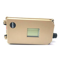
Samson TROVIS 3731-3 Operating Instructions Manual (132 pages)
3730 Series, 3731 Series
Brand: Samson
|
Category: Valve Positioners
|
Size: 3 MB
Table of Contents
Advertisement
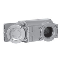
Samson TROVIS 3731-3 Mounting And Operating Instructions (116 pages)
Electropneumatic Ex d Positioner with HART communication
Brand: Samson
|
Category: Valve Positioners
|
Size: 8 MB
Table of Contents
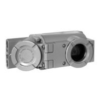
Samson TROVIS 3731-3 Mounting And Operating Instructions (100 pages)
3731 series
Electropneumatic Ex d
with HART communication
Brand: Samson
|
Category: Valve Positioners
|
Size: 2 MB
Table of Contents
Advertisement

Samson TROVIS 3731-3 Mounting And Operating Instructions (100 pages)
Electropneumatic Ex d Positioner With HART communication
Brand: Samson
|
Category: Valve Positioners
|
Size: 1 MB
Table of Contents
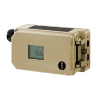
Samson TROVIS 3731-3 Operating Instructions Manual (40 pages)
EXPERT+ Valve Diagnostics
Brand: Samson
|
Category: Valve Positioners
|
Size: 1 MB
Table of Contents

Samson TROVIS 3731-3 Configuration Manual (28 pages)
Series 3730, Series 3731, (Ex d) Electropneumatic Positioners, HART Communication
Brand: Samson
|
Category: Valve Positioners
|
Size: 0 MB