Samson 3731-3 Mounting And Operating Instructions
Electropneumatic ex d positioner with hart communication
Hide thumbs
Also See for 3731-3:
- Mounting and operating instructions (116 pages) ,
- Operating instructions manual (132 pages) ,
- Configuration manual (28 pages)

Related Manuals for Samson 3731-3


Summary of Contents for Samson 3731-3
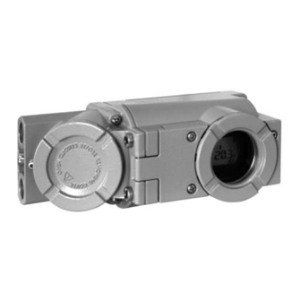
- Page 1 Electropneumatic Ex d Positioner Type 3731-3 ® With HART communication Fig. 1 · Type 3731-3 Mounting and Operating Instructions EB 8387-3 EN Firmware version 1.3x Edition November 2005...
-
Page 2: Table Of Contents
Contents Contents Page Design and principle of operation ....6 Communication ......7 Technical data . - Page 3 Contents Extended EXPERT diagnostics ..... 51 Classification of the status alarms and the condensed status ..52 Maintenance .
- Page 4 Safety instructions General safety instructions The positioner may only be assembled, started up or operated by trained and experienced personnel familiar with the product. According to these mounting and operating instructions, trained personnel is referred to as individuals who are able to judge the work they are assigned to and recognize possible dangers due to their specialized training, their knowledge and experience as well as their knowledge of the relevant standards.
- Page 5 Article code Article code Type 3731-3 X X X X X X 0 0 0 0 0 X X Explosion protection II 2 G EEx d IIC T6/II 2 G EEx de IIC T6 acc. to ATEX EEx d IIC T6 acc. to FM/CSA...
-
Page 6: Design And Principle Of Operation
The positioner is equipped with an interface VDI/VDE 3845. to allow the SAMSON TROVIS-VIEW Con- Springless rotary actuators require a revers- figuration and Operator Interface software ing amplifier included in the accessories to... -
Page 7: Communication
Design and principle of operation and one signal to a fault alarm contact (con- Communication densed status). The assignment of these signals to the The positioner is equipped with an interface A/B/C terminals is determined over for HART ® protocol (Highway Addressable Code 25. -
Page 8: Technical Data
Design and principle of operation Technical data Positioner Nominal travel, Direct attachment to Type 3277: 3.6 to 30 mm, attachment acc. to IEC 60534-6: adjustable 3.6 to 200 mm or 24° to 100° opening angle for rotary actuators Travel range Adjustable within the nominal travel/nominal angle, max. - Page 9 ® Communication (HART) HART field communication protocol For handheld communicator: device description for 3731-3, Software requirements For PC: DTM file acc. to Specification 1.2, suitable for integrating the positioner in frame (HART) applications that supports the FDT/DTM concept (e.g. PACTware);...
-
Page 10: Attachment To The Control Valve - Mounting Parts And Accessories
The positioner can be attached either di- as it will go in both directions to adapt it to rectly to a SAMSON Type 3277 Actuator or the internal measuring lever. according to IEC 60534-6 (NAMUR) to con-... - Page 11 Max. lever pin position 3277-5 25.0 120/240/350 35.4 3277 Actuator 10.0 50.0 Travel table for attachment acc. to IEC 60534-6 (NAMUR) SAMSON valves Other valves/actuators Required Assigned lever pin position cm² Rat. travel mm Min. Travel Max. 60 and 120 17.7...
- Page 12 Attachment to the control valve – Mounting parts and accessories Direct attachment Order no. Table 1 1400-7452 Mounting parts For actuators with 120 cm effective diaphragm area, see Fig. 3 1400-6819 Switchover plate (old) for Actuator Type 3277-5xxxxxx.00 (old) 1400-6822 Switchover plate new for Actuator Type 3277-5xxxxxx.01 (new) 1400-6820 Accessories...
- Page 13 Attachment to rotary actuators (VDI/VDE 3845 for all sizes of fixing level 2) see Figs. 7 and 8 Attachment acc. to VDI/VDE 3845 1400-9244 Mounting Attachment for SAMSON Type 3278 (also for VETEC Type S160 and Type R) 1400-9245 parts Attachment for Camflex II...
-
Page 14: Direct Attachment
Attachment to the control valve – Mounting parts and accessories Direct attachment 4. Press the brass restriction 1400-6964 from the accessories into the seal of the 2.1.1 Type 3277-5 Actuator signal pressure input at the actuator yoke. Refer to Table 1 on page 12 for the required 5. - Page 15 Attachment to the control valve – Mounting parts and accessories Symbols Lever Switchover plate (9) 1.1 Nut Actuator stem 1.2 Disk spring extends Follower pin Follower clamp Screw plug Attachment left Attachment right Stopper Connecting plate for G ¼ Actuator stem 6.1 Seal rings retracts Pressure gauge bracket...
-
Page 16: Type 3277 Actuator
Attachment to the control valve – Mounting parts and accessories 9. Mount cover (11) on the other side. 1. Place follower clamp (3) on the actuator Make sure that the vent plug points stem, align and screw tight so that the downwards when the control valve is in- mounting screw is located in the groove stalled to allow any condensed water... - Page 17 Attachment to the control valve – Mounting parts and accessories actuator symbol that corresponds with fixing screws and the cover. Then repo- the actuator with fail-safe action "Actua- sition the gasket (16) turned by 180°. tor stem extends" or "Actuator stem re- The previous version of the connection tracts."...
-
Page 18: Attachment According To Iec 60534-6
Attachment to the control valve – Mounting parts and accessories then the follower plate (3) to the bracket to- plate (13) to be turned such that the cor- gether with the bolts (14) and screws (14.1). responding actuator symbol points to the marking. - Page 19 Attachment to the control valve – Mounting parts and accessories Attachment to rod-type yoke Attachment to Rods with Ø max. 35 mm NAMUR rib Lever 1.1 Nut Disk spring Follower plate 3.1 Follower plate Additional bracket for Connecting plate actuators with 2800 cm only for G ¼...
-
Page 20: Attachment To Type 3510 Micro-Flow Valve
Attachment to the control valve – Mounting parts and accessories Attachment to Type 3510 6. Place lever (1) on the positioner shaft and screw tight using the disk spring Micro-flow Valve (1.2) and nut (1.1). The positioner is attached to the valve yoke using a bracket. - Page 21 Attachment to the control valve – Mounting parts and accessories 8. Place positioner on the bracket (10) in Adjust the lever (1) correspondingly. such a manner that the follower pin Screw the positioner to the bracket (10) slides into the groove of the clamp (3). using three fixing screws.
-
Page 22: Attachment To Rotary Actuators
(or the out- necessary. put of the pressure gauge bracket or 2. In case of SAMSON Type 3278 and connecting plate). VETEC S160 Rotary Actuator, screw the adapter (5) onto the free end of the shaft or place adapter (5.1) onto the shaft of... - Page 23 10.1 Screws 4.1 Screw Spacers 4.2 Disk spring 4.3 Adhesive label Actuator shaft or adapter 5.1 Adapter SAMSON Type 3278 Attachment acc. to VDE/VDI 3845, level 2 VETEC S160, VETEC R Fig. 8 · Attachment to rotary actuators EB 8387-3 EN...
-
Page 24: Reversing Amplifier For Double-Acting Actuators
Attachment to the control valve – Mounting parts and accessories 8. Place positioner on the housing (10) and Note! screw it tight. Considering the actuator's The sealing plug (1.5) in the Type 3731 direction of rotation, align lever (1) so Positioner should not be unscrewed out of that it engages in the correct slot of the the reversing amplifier. - Page 25 Attachment to the control valve – Mounting parts and accessories From the positioner Control signals to Reversing amplifer the actuator 1.1 Special screws 1.2 Gasket 1.3 Special nuts 1.4 Rubber seal 1.5 Sealing plug 1.6 Filter Fig. 9 · Mounting a reversing amplifier EB 8387-3 EN...
-
Page 26: Connections
Connections If the positioner is attached directly to the Connections Type 3277 Actuator, the connection of the positioner's output pressure to the actuator Pneumatic connections is fixed. For attachment according to IEC 60534-6 (NAMUR), the signal pressure Supply air can be routed to either the top or bottom di- The inlet pressure of the supply air may not aphragm chamber of the actuator, depend- exceed 6 bar. - Page 27 Connections For tight-closing valves, the maximum signal pressure pst is roughly estimated as fol- lows: ⋅ ⋅ π Δ = F + [bar] ⋅ d = Seat diameter [cm] Δp = Differential pressure across the valve [bar] A = Actuator diaphragm area [cm = Upper bench range of the actuator [bar] If there are no specifications, calculate as...
-
Page 28: Electrical Connections
Connections In case the temperature exceeds 70 °C at Electrical connections the cable entries, appropriate temperature- resistant connecting leads must be used. For electrical installation, you are re- The positioner must be integrated into the quired to observe the relevant equipotential bonding system on site. - Page 29 Connections The threaded connections for the terminal The position transmitter is operated in a compartment are designed as ½ NPT or two-wire circuit. The usual supply voltage is M20x1.5 connections. 24 V DC. Considering the resistance of the supply leads, the voltage at the position The electrical connections are intended to be transmitter terminals can be between 11 V connected to screw terminals for wire...
-
Page 30: Establishing Communication
Connections If the load impedance of the controller or 3.2.1 Establishing communication control station is too low, an isolation ampli- Communication between PC and the FSK fier functioning as load converter is to be modem or handheld communicator and connected between controller and ®... - Page 31 Connections Standard bus (Multidrop): In the standard bus (Multidrop) mode, the positioner follows the analog current signal (reference variable) as for point-to-point communication. This operating mode is, for example, suitable for split-range operation of positioners (series connection). The bus address/polling address has to be within a range of 1 to 15.
-
Page 32: Operation
Operation Operation Enabling and selecting parameters The positioner is operated using the black rotary pushbutton which is only accessible The codes which are marked with an aster- after opening the screwed down protective isk (*) in section 9 on page 55 onwards cover on the front of the positioner. - Page 33 Operation Manual operation Control operation Condensed status: Fault Code Bar graph for system deviation Designation or lever position Position Units Parameter Limit switch Limit switch Alarm 2 Alarm 1 Condensed status: Configuration Fail-safe position Maintenance required enabled active Maintenance demanded Displays and their meaning Maximum range TunE...
-
Page 34: Operating Modes
Operation Operating modes Note! To cancel a value that you have just entered 4.2.1 Automatic and manual ope- under a code, turn the button until ESC ap- rating modes pears on the display and press to confirm. After initialization has been completed suc- cessfully for the first time, the positioner is automatically in automatic operating... -
Page 35: Safe - Fail-Safe Position
Operation Adjusting the manual set point 4.2.2 SAFE – Fail-safe position If you want to move the valve to fail-safe po- sition, proceed as follows: Select Code 0 , press the button, AUtO or MAN appears on the display, Code 0 blinks. -
Page 36: Start-Up - Settings
Start-up – Settings Start-up – Settings Adapting the display Undo fastening screws and flip open the The data representation on the positioner protective cover on the enclosure. display can be turned by 180°. If the displayed data appear upside down, Connect pneumatic supply air proceed as follows: (Supply 9), making sure the pressure is... -
Page 37: Checking The Operating Range Of The Positioner
Start-up – Settings Checking the operating when the displayed angle is greater than 30°, and the outer right or left bar range of the positioner graph element blinks. To check the mechanical attachment and the If this is the case, it is absolutely neces- proper functioning, the valve should be sary to check lever and pin position as moved through the operating range of the... - Page 38 Start-up – Settings Double-acting actuators must always be set Simplified start-up! to AIR TO OPEN ( AtO ). Connect the pneu- For most applications, the positioner with its default settings is ready for operation, matic connections of the reversing amplifier as described in section 2.5.
-
Page 39: Positioner Initialization
Start-up – Settings Select Code 0 and press the button. MAN Positioner initialization appears on the display. During initialization the positioner adapts it- Code 0 blinks. self optimally to the friction conditions and the signal pressure demand of the control valve. -
Page 40: Initialization Modes
Start-up – Settings tions start plotting the reference graphs after After a successful initialization, the the initialization process has been com- positioner runs in control operation indi- pleted. See note at the end of this section. cated by the control symbol. A malfunctioning leads to the process being Warning! interrupted. - Page 41 Start-up – Settings MAX – Initialization based on maximum Keep the button pressed down for at least range 6 seconds! The initialization procedure starts. Initialization mode for simplified start-up for The initialization procedure may valves with two clearly defined mechanical take several minutes, depending on travel stops, e.g.
- Page 42 Start-up – Settings After configuration has been enabled: NOM – Initialization based on nominal range Initialization mode for all globe valves. For this initialization mode, pin position Default OFF (Co de 4 ), nominal travel/angle (Code 5 ) must be entered. Turn button →...
- Page 43 Start-up – Settings Turn button → MAN , press button. The initialization procedure may take several minutes, depending on the actuator size. The valve moves through its entire travel/angle of ro- tation range. Positioners with EXPERT diagnostic func- tions automatically start plotting the refer- Turn button →...
- Page 44 Start-up – Settings The set fail-safe position AtO or AtC ap- sure signal which is routed to the actuator pears on the display. externally. The blocking position ensures that the plant continues to operate with this Keep the button pressed down for at least valve position.
- Page 45 Start-up – Settings Enable configuration: Default ää Default OFF Turn button → Code 7 , press button, Turn button → Code 3 , Turn button → Retain direction of action ää or select äæ press button, turn button → ON , press button. Press button.
- Page 46 Start-up – Settings Retain default value, change value only if Start initialization: Turn button → Code 0 , necessary. Turn button → Select K press button, Turn button → Init press button. press button. The set fail-safe position AtO or AtC appears on the display. Default 2 Keep the button pressed down for at least 6 seconds! The initialization procedure...
- Page 47 Start-up – Settings Canceling the blocking position Zero point correction Finally, if process operations allow it, the For the positioner to follow its reference zero point must be adjusted according to variable again, the blocking position must section 5.7 on page 49. be canceled and the positioner must be set to automatic operation AUtO as follows: Turn button →...
-
Page 48: Fault/Failure
Start-up – Settings fer to the codes listed in section 9 on Fault/failure page 55 onwards All status and fault alarms are assigned a classified status in the positioner. Display indicating an To provide a better overview, the classified error code alarms are summarized in a condensed sta- tus for the positioner (see section 6). -
Page 49: Zero Calibration
Start-up – Settings Zero calibration The valve briefly moves from the cur- rent travel/angle of rotation position In case of discrepancies with the closing po- to the closed position. sition of the valve, e.g. with soft-sealed plugs, it may become necessary to recalibrate the zero point. -
Page 50: Start-Up Via Local Interface (Ssp)
Specification 1.2 is available for 1400-7700). communication. This allows the device, for Use the TROVIS-VIEW software with 3731-3 example, to be run with the PACTware op- device module installed which allows you to erator interface. All the positioner's parame- access all the device parameters. -
Page 51: Status And Diagnostic Alarms
Status and diagnostic alarms Status and diagnostic alarms Extended EXPERT diagnostics The Type 3731-3 Positioner contains an in- tegrated diagnostic approach to generate In addition to the standard EXPERT diagnos- classified status and diagnostic alarms. tic features, the optional EXPERT... -
Page 52: Classification Of The Status Alarms And The Condensed Status
Status and diagnostic alarms the positioner. Additionally, it is possible to Maintenance required activate EXPERT at a later point in time in The positioner still performs its control task an existing positioner. (with restrictions). A maintenance For this purpose, an activation code can be requirement or above average wear has ordered, specifying the serial number of the been determined. - Page 53 Status and diagnostic alarms Classification process in the positioner Note! An alarm is assigned to one of following All additional alarms generated by EXPERT classified states in the table: have the status “No alarm” by default. Condensed status Logging and displaying diagnostic To provide a better overview, the state of the functions/alarms positioner is summarized in a condensed...
-
Page 54: Maintenance
Maintenance Maintenance Servicing explosion-protected devices The positioner does not require any mainte- nance. If a part of the positioner on which the ex- plosion protection is based needs to be ser- There are filters with a 100 μm mesh size in viced, the positioner must not be put back the pneumatic connections for supply and into operation until an expert has inspected... -
Page 55: Code List
Code list Code list Code Parameter – Display, values Description [default setting] Important! Codes with marked with an asterisk (*) must be enabled with Code 3 prior to configuration. AUtO = Automatic mode MAN = Manual mode Operating mode SAFE = Fail-safe position ESC = Escape [MAN]... - Page 56 Code list Pin position The follower pin must be inserted into the correct pin position according to the valve travel/angle of rotation. [OFF] This pin position must be entered for initialization using NOM or 17, 25, 35, 50 mm SUb. 70, 100, 200 mm, 90°...
- Page 57 Code list Direction of action of the reference variable w in relation to the travel/angle of rotation x (increasing/increasing or [ää] increasing/decreasing) äæ Automatic adaptation: AIR TO OPEN: On completing initialization, the direction of action remains increasing/increasing (ää), a globe valve opens as the mA signal increases.
- Page 58 Code list Upper x-limit Limitation of the travel/angle of rotation upwards to the entered value, the characteristic is not adapted. [100 %] 50.0 to 120.0 [100] % of Example: In some applications, it may be a good idea to limit the the operating range valve travel, e.g.
- Page 59 Code list If w approaches the final value up to the adjusted percentage Final position w > that causes the valve to open, the actuator is immediately [OFF] completely filled with air (with AIR TO OPEN) or vented (with AIR 50.0 to 100.0 % TO CLOSE).
- Page 60 Code list Tolerance band Used for error monitoring 0.1 to 10.0 [5] % of the Determination of the tolerance band in relation to the operating operating range range. Associated lag time [30] s is a reset criterion. If a transit time is determined during initialization, which is 6 times >...
- Page 61 Code list This code allows you to find out on site whether the device has an Binary output optional binary output or not. When a binary output exists, its [- / -] switching performance can be read and set. If there is no binary output, “- - - -” appears on the display of the positioner.
- Page 62 Code list Position transmitter x/ix Operating direction of the position transmitter; indicates how the travel/angle position is assigned to the output signal i, based on [ää] the closed position. äæ The operating range (see Code 8) of the valve is represented by the 4 to 20 mA signal.
- Page 63 Code list Entering the blocking position. Blocking position Distance up to the CLOSED position. [0] mm/° /% Only necessary in SUb initialization mode. Reset Resets all parameters to default (factory setting). Note: After setting RUN, the positioner must be re-initialized. [OFF] Display only, Position transmitter...
- Page 64 Code list Forced venting info Display only, indicates whether the forced venting option is installed. HIGH/LOW No forced venting function installed Forced venting installed If a voltage supply is connected at the terminals of the forced venting function, YES and HIGH appear on the display in alter- nating sequence.
- Page 65 Code list Diagnostics Diagnostic parameters d0 Current temperature Operating temperature [°C] inside the positioner (precision approx. 2.4 %) –55 to 125 d1 Minimum temperature The lowest temperature below 20 °C that has ever occurred. [20] d2 Maximum temperature The highest temperature above 20 °C that has ever occurred. [20] d3 Number of zero The number of zero calibrations since the last initialization.
- Page 66 Code list Error codes – Remedy Condensed status alarm active, when prompted, Err appears. If there are any fault alarms, they are displayed here. Initialization error (indicated on the display by the condensed status with the corresponding classification) The value supplied by the measuring signal is either too high or x <...
- Page 67 Code list The initialization routine lasts too long. The positioner returns to Init time > its previous operating mode. • No pressure on the supply line or there is a leak. • Supply air failure during initialization. Remedy Check attachment and supply pressure. Re-initialize the positioner.
- Page 68 The positioner switches to emergency mode where the position cannot be accurately controlled anymore. However, the positioner continues operation according to its reference variable signal so that the process remains in a safe state. Remedy Return the positioner to SAMSON AG for repair. EB 8387-3 EN...
- Page 69 Additional alarm at the fault alarm contact! Valve moves to the fail-safe position. Remedy Return the positioner to SAMSON AG for repair. The hardware positioner is monitored by means of a test Test calculation calculation.
- Page 70 Calibration disturbances. Subsequently, the device runs on default values Additional alarm at the fault alarm contact! Remedy Return the positioner to SAMSON AG for repair. Parameter errors that are not critical for the control. General parameters Remedy Confirm error. Check and, if necessary, reset required parameters.
- Page 71 Remedy Interrupt current and restart positioner. Otherwise, return the positioner to SAMSON AG for repair. Errors in options parameters, e.g. due to EMC disturbances. Options parameter Remedy Return the positioner to SAMSON AG for repair. Diagnostic alarms Alarms are generated in the EXPERT extended diagnostics if EXPERT has been successfully activated in Code 48.
-
Page 72: Setting With Trovis-View Software - Parameter List
The Activation dialog box will stalling the TROVIS-VIEW Configuration come up displaying the generated request and Operator Interface is provided by code and an Internet link to SAMSON’s ac- SAMSON. tivation server where a unique activation The system requirements are specified in the code will then be generated and displayed. -
Page 73: Starting Trovis-View And Performing Basic Settings
Setting with TROVIS-VIEW software – Parameter list Upload data from the positioner and 10.2 Starting TROVIS-VIEW and display them in the operator interface performing basic settings Settings may be entered into the TROVIS-VIEW operator interface when ei- Download data onto the positioner ther the positioner is connected or not con- from the operator interface nected. - Page 74 Setting with TROVIS-VIEW software – Parameter list 1. Start TROVIS-VIEW. Make required settings in View menu by activating or deactivating functions. When the Trend Viewer is activated, all operating data are uploaded cyclically from the positioner in online mode and shown in the form of graphs. Right-click on the graph to edit the graph format or to copy the logged data to a file.
- Page 75 Setting with TROVIS-VIEW software – Parameter list 3. Select Communication from the Options menu and choose. communication settings. 4. Click on Port settings and select port as well as server setting. 5. Select Convert in the File menu to select the firmware version of the positioner.
-
Page 76: Setting The Parameters
Setting with TROVIS-VIEW software – Parameter list 10.3 Setting the parameters Click on one of the folders listed in the left column to open a window listing the settings of the corresponding parameters. Place the mouse arrow on the parameter name to open a tool tip providing information about that particular parameter. -
Page 77: Parameter List
Text field 1 to 5 Max. 32 characters Positioner serial Serial number of the positioner number Positioner product 3731-3 xxx Manufacturer model number of the positioner number Firmware version x.xx Current firmware version of device, Code 43 Diagnosis level EXPERT... - Page 78 Parameter list Identification – Positioner Device type 3731-3 Indicates exact model designation Identification – Positioner – Actuator Type identification Manufacturer ID number of the actuator that the actuator positioner is mounted upon Actuator type Single-acting Single-acting Actuator with or without spring return...
- Page 79 Parameter list Flow characteristic Linear 30:1/ Linear 50:1 Valve characteristic: Flow to valve travel Eq. perc. 30:1/ Linear 50:1/ Eq. perc. 50:1/ Other Valve dimensions DIN/ANSI Valve dimensions according to DIN or ANSI standard Nominal size DN 8...2100 Nominal size in mm (DIN) or inch (ANSI) Kvs coefficient 0.0001...
- Page 80 Parameter list Status Condensed state Summarized state of the positioner. The condensed status is made up from the various states. The condensed status can take on the following states: No alarm Maintenance required Maintenance demanded Failure Function check The condensed states “Maintenance required” and “Maintenance demanded”...
- Page 81 Parameter list Positioner – Reference variable Direction of action Increasing/ Increasing/ Code 7 increasing >> increasing >> Incr./decr. <> Lower reference 0.0...75.0 % 0.0 % Code 12 range value Upper reference 25.0...100.0 % 100.0 % Code 13 range value Enable final On/Off Code 14 position smaller...
- Page 82 Parameter list Positioner – Characteristic Characteristic Linear Linear Code 20 selection Equal percentage Eq. perc. reverse SAMSON butterfly valves linear eq. perc. VETEC rotary plug valves linear eq. perc. Segmented ball valves linear eq. perc. Graphs of the user-defined characteristics, loading and saving characteristics.
- Page 83 Parameter list Example for user-defined characteristic • Select User defined characteristic in Characteristic selection parameter. • Double-click on Edit, open or save characteristic to open a window where the characteristic can be edited. Click on Characteristic button on the bottom right to open and save a characteristic. •...
- Page 84 Parameter list Parameter Values Default Description Positioner – Performance characteristics Required 0...17 Code 17 proportional-action coefficient KP (step) Proportional-action Code 17 coefficient KP (step) Required Off/1/2/3/4 Code 18 derivative-action time TV (step) Derivative-action Code 18 time TV (step) Positioner – Fail-safe action Fail-safe position Closing Fail-safe action of the actuator upon...
- Page 85 Parameter list “Maintenance Yes/No Code 33 required” condensed status Zero point limit 0.0...100.0 % 5.0 % Limit for zero point monitoring Positioner – Error control – Classification report Condensed status fault alarms Note! Each fault alarm has a status assigned to it. The possible states are placed in order starting with the lowest priority: No alarm Alarm is not added to the condensed status...
- Page 86 Parameter list x > range Code 50 Delta x < range Code 51 Attachment Code 52 Initialization time Code 53 Determines the individual status exceeded for each alarm Initialization/ Code 54 solenoid valve with symbol Transit time not Code 55 achieved Pin position Code 56...
- Page 87 Parameter list Positioner – Start-up Reading direction Pneumatic Pneumatic Code 2 connection connection right/left right Pin position Code 4 17/25/35/50/ 70/100/200 mm 90° Initialization mode Nominal range Maximum Code 6 range Maximum range Manual adjustment Substitution Pressure limit Off /1.4 / 2.4 Code 16 /3.7 bar Determined...
- Page 88 Parameter list Initialization Running initialization procedure has been canceled canceled. The control valve moves to its fail-safe position. Target operating Automatic Automatic Code 0 mode Manual SAFE Current operating Indicates current operating mode of positioner mode Initialization error x > range Code 50 Delta x <...
- Page 89 Parameter list Positioner – Simulation Alarm test A1 Code 28 Alarm test A2 Code 28 Alarm test A3 Code 28 (alarm fault output) Diagnosis Diagnosis level EXPERT setting Current operating Automatic Indicates current operating mode of positioner mode Diagnosis – Status alarms Status Condensed status Alarm symbol...
- Page 90 Parameter list Number of zero Number of zero calibrations performed since calibrations last initialization Number of Number of initializations performed initializations Zero point limit Limit for zero point monitoring Operation Control loop Code 57 Zero point Code 58 Autocorrection Code 59 Fatal error Code 60 Alarm...
- Page 91 Parameter list Data memory Control parameter Code 68 Poti parameter Code 69 Calibration Code 70 parameter General parameters Code 71 Internal device Code 73 Alarm error 1 HART parameter Code 74 Info parameter Code 75 Option parameter Code 78 Diagnostic Code 80 parameters Temperature...
- Page 92 Parameter list Reset initialization error Reset x > range Code 50 Reset Delta x < Code 51 range Reset attachment Code 52 Reset initialization Code 53 Resetting corresponding exceeded alarms Reset initialization/ Code 54 solenoid valve Reset transit time Code 55 too short Reset pin position Code 56...
- Page 93 Parameter list EB 8387-3 EN...
-
Page 94: Dimensions In Mm
Dimensions in mm Dimensions in mm Pressure gauge or connecting plate Attachment acc. to IEC 60534-6 bracket (G ¼ only) Lever mm S = 17 M = 50 L = 100 XL = 200 Direct attachment Electrical connections: 2x female threads ½... -
Page 95: Test Certificates
EB 8387-3 EN... - Page 96 EB 8387-3 EN...
- Page 97 EB 8387-3 EN...
- Page 98 EB 8387-3 EN...
- Page 99 EB 8387-3 EN...
- Page 100 SAMSON AG · MESS- UND REGELTECHNIK Weismüllerstraße 3 · 60314 Frankfurt am Main · Germany Phone: +49 69 4009-0 · Fax: +49 69 4009-1507 EB 8387-3 EN Internet: http://www.samson.de...
Need help?
Do you have a question about the 3731-3 and is the answer not in the manual?
Questions and answers