Table of Contents

Subscribe to Our Youtube Channel
Related Manuals for HIOS BLT-AY-61


Summary of Contents for HIOS BLT-AY-61
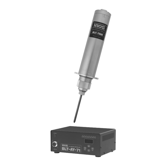
- Page 1 Driver Controller for Automatic BLF Brushless Screwdriver BLT-AY-61 BLT-AY-71 Operation Manual (As of September of 2017) HIOS Inc. 1-16-5 Akiyama, Matsudo City, Chiba Pref., Japan 270-2223 Phone: 81-47-392-2001 FAX: 81-47-392-7773 No. ET-A048...
-
Page 2: Table Of Contents
Contents ■ Introduction ............................3 ■ Outline ..............................4 ■ Precautions ............................. 5 ■ BLT-AY-61/BLT-AY-71 Specifications .................... 6 ■ Exterior Drawings ..........................7 ■ Main Functions ............................. 8 ■ Main Terminology ..........................9 ■ Front Panel ............................. 10 ■ Rear Panel Input / Output ........................ 11 ■... -
Page 3: Introduction
Store this instruction manual in a safe place for future reference. BLT-AY-71 is only up to 120V ac for warranty more then 120V ac, HIOS can not take any respon- sibility. -
Page 4: Outline
The BLT-AY-61 and BLT-AY-71 Driver controller uses a brushless motor and not use consumable parts such as carbon brush. That saves much of maintenance efforts for this driver. -
Page 5: Precautions
● Do not install the unit in an area where it may be subjected to dust or metal fragments. ● Do not use the unit with anything other than HIOS drivers as this will cause the unit to mal- function. -
Page 6: Blt-Ay-61/Blt-Ay-71 Specifications
■ BLT-AY-61/BLT-AY-71 Specifications BLT-AY-61 BLT-AY-71 Input Voltage AC100-240V (47-63Hz) Power 100W Fuse Rating 3A/250V (spare fuse included) Dimensions See p.7 for Exterior Drawings. Weight Approximately 1.75kg (main unit only) Driver (See p19, 20) BLF-7000 or BLF-7000X and Compatible Drivers... -
Page 7: Exterior Drawings
■ Exterior Drawings BLT-AY-61 and BLT-AY-71 have common exterior drawings. (Front View) Unit: mm (Overhead View) (Right Side View) Input terminal block Front Front ∅ Footing size 4- (Caution) The above exterior drawing of the power supply for brushless screwdrivers Not to scale. -
Page 8: Main Functions
■ Main Functions 1. The motor control circuitry is incorporated into the BLT-AY-61/ BLT-AY-71, giving the driver a simpler construction. 2. The internal buzzer can be turned off (internal SW 6-1). 3. The FOR input for forward rotation from an external source can be switched between pulse and reading (internal SW 6-2). -
Page 9: Main Terminology
■ Main Terminology 1. Tightening Check (setting the impact number) To check that the screw has been tightened properly or to tighten the screw further, the screw is tightened two or three times after the initial tightening. A tightening check can also be referred to as a second tightening or re-tightening. -
Page 10: Front Panel
■ Front Panel 4. Setting Value 3. Operation Display LED Segment Display 5. Function Button ▲ UP Button ▼ DOWN Button ENT Button 2. Driver Connector 1. Main SW A green LED will light up when the power is turned ON, and the operation display LEDs and all segments of the value display will light up for 1 second. -
Page 11: Rear Panel Input / Output
■ Rear Panel Input / Output External I/O terminal Terminal block connector 1. Main SW on the main body Model number: XW4A-10B1-V1 Inlet with Fuse Holder 3 A / 250 V Accessories: Power supply side Terminal block connector Input / Signal Name Outline Output... -
Page 12: Display When The Power Is On With The Default Settings
DRIVER The BLT-AY-61 and BLT-AY-71 can be switched between 2WS HIGH (20 – 30) and 2WS LOW (5 – 15) by turning 2WS ON / OFF. The bit can be rotated in reverse by turning REV (reverse rotation input) ON / OFF. -
Page 13: How To Switch Between Reading Start/Pulse Start
■ How to switch between Reading Start/Pulse Start 1) Turn the power to the BLT-AY-61 or BLT-AY-71 off and remove the power cable from the power outlet. 2) Remove the driver cable from the plug on the main unit. 3) Remove the cover of the main unit. Take care not to lose the screws. -
Page 14: Mode Settings 1
MODE Settings 1 (1) Hold down the Function Button "Beep (2 seconds) beep beep" (2) Forward rotation (2WS – HIGH) torque up settings Use ▲ / ▼ to change the settings (U0 to U4 and d0 to d4) Always check the changes with ENT. If changes to other settings are not required, hold down the Function Button to complete the setting process. -
Page 15: Mode Settings 2
MODE Settings 2 (6) Forward rotation (2WS – LOW) torque up settings Use ▲ / ▼ to change the settings (U0 to U4 and d0 to d4) Always check the changes with ENT. If changes to other settings are not required, hold down the Function Button to complete the setting process. -
Page 16: Torque Up Settings
The BLT-AY-61/BLT-AY-71 controller is designed to control the rotational speed of the driver over a large range of speeds from low to high, as well as to allow settings for torque up with DOWN trigger at low speeds and UP trigger at high speeds. -
Page 17: Clutch Mechanism
■ Clutch Mechanism The clutch mechanism is described below. Diagram of the mechanism that 1 Torque adjustment Detection SW allows the driver to pressure "OFF" detect torque. Roller Movement to traverse cam Torque adjustment pressure 2 Detection SW "ON" If the speed when traversing the cam is high, the detection Movement to... -
Page 18: Input/Output Connections
■ Input/Output Connections Internal Power / DC 24V Input/Output circuit layout The input circuit consists of a photo coupler. Drop Internal the input terminal to GND circuit level using an open col- lector. FOR input terminal RESET input terminal Same as above circuit layout 2WS input terminal Same as above circuit layout REV input terminal... -
Page 19: Relationship Between Rpm And Torque
■ Relationship between RPM and Torque (BLF-2000 / BLF-5000) For the unloaded rotation speed, consider the value in the chart with the range of ± 10%. Screwdriver BLF-2000* BLF-5000 Speed Set- Max Torque Min Torque Max Torque Min Torque ting 120 r.p.m 115 r.p.m 150 r.p.m... -
Page 20: Relationship Between Rpm And Torque
■ Relationship between RPM and Torque (BLF-7000 Series) For the unloaded rotation speed, consider the value in the chart with the range of ± 10%. Screwdriver BLF-7000 / BLF-7000X BLF-7025X Speed Set- Max Torque Min Torque Max Torque Min Torque ting 150 r.p.m 120 r.p.m... -
Page 21: Timing Chart Table
■ Timing Chart Table Note 1: If a pulse input is to be used for START and RESET, always use an input of 100 mS or more. Note 2: Set the interval between one START and the next START to 100 mS or more for the reading START settings. -
Page 22: Timing Chart 01-18
Timing Chart 01 Impact setting value Start Type 2WS setting Bit rotation FOR/ FOR/ REV/ REV/ HIGH HIGH Pulse start ー ー ー HIGH only FOR only Use “Pulse input” for the Use “Pulse input” for the RESET input to stop the FOR input to rotate the rotation of the driver driver... - Page 23 Timing Chart 02 Impact setting value Start Type 2WS setting Bit rotation FOR/ FOR/ REV/ REV/ HIGH HIGH Pulse start ー ー ー HIGH only FOR only Pulse is input for the FOR input and Use “Pulse input” for the FOR in- the driver is rotated freely (if used for put to rotate the driver meshing the screw)
- Page 24 Timing Chart 03 Impact setting value Start Type 2WS setting Bit rotation FOR/ FOR/ REV/ REV/ HIGH HIGH Pulse start ー ー ー LOW only FOR only Use “Pulse input” for the Use “Pulse input” for the FOR input to rotate the RESET input to stop the driver rotation of the driver...
- Page 25 Timing Chart 04 Impact setting value Start Type 2WS setting Bit rotation FOR/ FOR/ REV/ REV/ HIGH HIGH Pulse start ー ー ー LOW only FOR only Pulse is input for the FOR input and Use “Pulse input” for the FOR in- the driver is rotated freely (if used for put to rotate the driver meshing the screw)
- Page 26 Timing Chart 05 Impact setting value Start Type 2WS setting Bit rotation FOR/ FOR/ REV/ REV/ HIGH HIGH Pulse start ー ー ー LOW → HIGH FOR only Use “Pulse input” for the Use “Pulse input” for the FOR input to rotate the RESET input to stop the driver rotation of the driver...
- Page 27 Timing Chart 06 Impact setting value Start Type 2WS setting Bit rotation FOR/ FOR/ REV/ REV/ HIGH HIGH Pulse start ー ー ー HIGH → LOW FOR only Use “Pulse input” for the Use “Pulse input” for the FOR input to rotate the RESET input to stop the driver rotation of the driver...
- Page 28 Timing Chart 07 Impact setting value Start Type 2WS setting Bit rotation FOR/ FOR/ REV/ REV/ HIGH HIGH ー ー ー LOW → HIGH REV only FOR input RESET input Bit rotation Screw condition Torque up FINISH output 2WS input REV input The timing charts are applied to screwdrivers for counter-clock-wise for automatic BLF brush- less screwdriver.
- Page 29 Timing Chart 08 Impact setting value Start Type 2WS setting Bit rotation FOR/ FOR/ REV/ REV/ HIGH HIGH ー ー ー HIGH → LOW REV only FOR input RESET input Bit rotation Screw condition Torque up FINISH output 2WS input REV input The timing charts are applied to screwdrivers for counter-clock-wise for automatic BLF brush- less screwdriver.
- Page 30 Timing Chart 09 Impact setting value Start Type 2WS setting Bit rotation FOR/ FOR/ REV/ REV/ HIGH HIGH Pulse start ー ー ー HIGH only REV → FOR FOR input *Use “Pulse input”t of 100 mS or more RESET input Bit rotation Screw condition Torque up...
- Page 31 Timing Chart 10 Impact setting value Start Type 2WS setting Bit rotation FOR/ FOR/ REV/ REV/ HIGH HIGH Pulse start ー ー ー HIGH only FOR → REV *Use “Pulse input” of 100 mS or more FOR input RESET input Bit rotation Screw condition Torque up...
- Page 32 Timing Chart 11 Impact setting value Start Type 2WS setting Bit rotation FOR/ FOR/ REV/ REV/ HIGH HIGH Reading start ー ー ー HIGH only FOR only FOR input RESET input Bit rotation Freely rotate the bit to mesh with the screw Screw condition Torque up FINISH output...
- Page 33 Timing Chart 12 Impact setting value Start Type 2WS setting Bit rotation FOR/ FOR/ REV/ REV/ HIGH HIGH Reading start ー ー ー HIGH only FOR only Pulse is input for the FOR input and Rotate stops with RESET the driver is rotated freely (if used for meshing the screw) FOR input RESET input...
- Page 34 Timing Chart 13 Impact setting value Start Type 2WS setting Bit rotation FOR/ FOR/ REV/ REV/ HIGH HIGH Reading start ー ー ー LOW only FOR only FOR input RESET input Bit rotation Freely rotate the bit to mesh with the screw Screw condition Torque up FINISH output...
- Page 35 Timing Chart 14 Impact setting value Start Type 2WS setting Bit rotation FOR/ FOR/ REV/ REV/ HIGH HIGH Reading start ー ー ー LOW only FOR only Rotate stops with RESET FOR input RESET input Bit rotation Screw condition Torque up FINISH output 2WS input Impact starts when the...
- Page 36 Timing Chart 15 Impact setting value Start Type 2WS setting Bit rotation FOR/ FOR/ REV/ REV/ HIGH HIGH Reading start ー ー ー LOW → HIGH FOR only FOR input RESET input Bit rotation Screw condition Torque up FINISH output 2WS input REV input Input 2WS before the FOR...
- Page 37 Timing Chart 16 Impact setting value Start Type 2WS setting Bit rotation FOR/ FOR/ REV/ REV/ HIGH HIGH Reading start ー ー ー HIGH → LOW FOR only FOR input RESET input Bit rotation Screw condition Torque up FINISH output 2WS input REV input - 37 -...
- Page 38 Timing Chart 17 Impact setting value Start Type 2WS setting Bit rotation FOR/ FOR/ REV/ REV/ HIGH HIGH Reading start ー ー ー HIGH only REV → FOR FOR input RESET input Bit rotation Screw condition Torque up FINISH output 2WS input REV input - 38 -...
- Page 39 Timing Chart 18 Impact setting value Start Type 2WS setting Bit rotation FOR/ FOR/ REV/ REV/ HIGH HIGH Reading start ー ー ー HIGH only FOR → REV FOR input RESET input Bit rotation Screw condition Torque up FINISH output 2WS input REV input The timing charts are applied to screwdrivers for counter-clock-wise for automatic BLF brush-...
-
Page 40: After-Sale Service
- 40 -...
Need help?
Do you have a question about the BLT-AY-61 and is the answer not in the manual?
Questions and answers