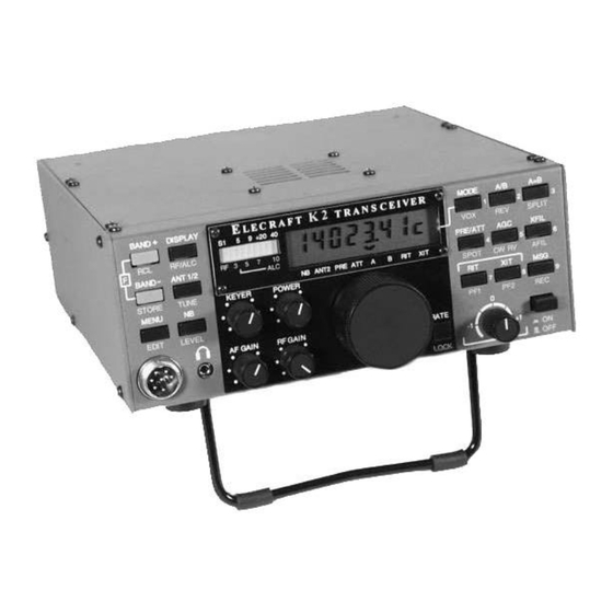
ELECRAFT K 2 Owner's Manual
160-10 meter ssb/cw transceiver
Hide thumbs
Also See for K 2:
- Owner's manual (161 pages) ,
- Instruction manual (16 pages) ,
- Troubleshooting (3 pages)
Advertisement
Quick Links
Advertisement

Subscribe to Our Youtube Channel
Related Manuals for ELECRAFT K 2


Summary of Contents for ELECRAFT K 2
- Page 1 Owner’s Manual Revision XC, Jan. 25, 1999 © Copyright 1999 Elecraft All Rights Reserved This revision of the K2 Owner’s Manual is for use by Field Test participants only. Missing or inaccurate information will be corrected in the next revision.
-
Page 2: Table Of Contents
K2 Manual 1/24/99 V.XC ©1999 Elecraft Table of Contents INTRODUCTION ....................................4 SPECIFICATIONS.................................... 4 PREPARATION FOR ASSEMBLY ..............................7 CONTROL BOARD ..................................13 FRONT PANEL BOARD ................................22 RF BOARD..................................... 34 FINAL ASSEMBLY..................................78 OPERATION ....................................81 MODIFICATIONS ..................................110 10. - Page 3 K2 Manual 1/24/99 V.XC ©1999 Elecraft...
-
Page 4: Introduction
10 watts. You can also customize your K2 by choosing from a wide range of internal option kits. These include: In addition to this owner’s manual, you’ll find extensive support for the K2 on our website, www.elecraft.com. Among the available materials are § SSB adapter manual updates, application notes, photographs, and information on new §... -
Page 6: Specifications
K2 Manual 1/24/99 V.XC ©1999 Elecraft 2. Specifications All measurements were made with a 13.8V supply and 50 ohm load at the antenna. Numeric values are typical; your results may be somewhat different. Specifications are preliminary and subject to change without notice. - Page 7 K2 Manual 1/24/99 V.XC ©1999 Elecraft Frequency range, MHz Load Tolerance 2:1 or better SWR recommended; Guaranteed 3.5-4.0, 7.0-7.3, will survive occasional operation 10.0-10.2, 14.0-14.5, 18.0-18.2, into high SWR 21.0-21.6, 24.8-25.0, 28.0-28.8 Typical [TBD] T-R delay 10ms-1.5sec, adjustable 160m (opt.) 1.8-2.0...
- Page 8 K2 Manual 1/24/99 V.XC ©1999 Elecraft Keyer Keying modes Iambic A and B Speed Range Approx. 9 - 40 WPM Messages 3 buffers, 84 bytes each, nonvolatile; auto-repeat...
-
Page 9: Preparation For Assembly
K2 Manual 1/24/99 V.XC ©1999 Elecraft 3. Preparation for Assembly Overview of the Kit As shown in Figure 3-2, there are three printed circuit boards (PCBs) in the basic K2 kit: the Front Panel board, Control Board, and RF board. - Page 10 K2 and its three circuit boards in various stages of assembly. If any of the above items is missing or damaged, contact Elecraft. Note to Field Testers Your kit has been carefully packed, so it is unlikely that any components are missing.
- Page 11 K2 Manual 1/24/99 V.XC ©1999 Elecraft Tools Assembly Notes The following specialized tools are supplied with the K2: This symbol is used to alert you to important information about § .050” (1.3mm) Allen Wrench, short handle assembly, alignment, or operation of the K2. You should read and §...
- Page 12 K2 Manual 1/24/99 V.XC ©1999 Elecraft Components which are mounted on the bottom of a board are identified example, a 1,500 ohm (1.5k) 5% resistor has color bands BROWN, on the schematic with this symbol: GREEN, and RED. A 1.5k, 1% resistor has color bands BROWN, GREEN, BLACK, BROWN.
- Page 13 K2 Manual 1/24/99 V.XC ©1999 Elecraft Resistor Color Code Tolerance (gold = 5%) Multiplier Second Digit First Digit Color Digit Multiplier Black Brown x 10 x 100 Orange x 1K Yellow x 10K Green x 100K Blue x 1M Violet...
- Page 14 K2 Manual 1/24/99 V.XC ©1999 Elecraft Integrated Circuits and ESD The K2 transceiver uses integrated circuits and transistors that can be damaged by electrostatic discharge (ESD). Problems caused by ESD can often be difficult to troubleshoot because components may only be degraded rather than fail completely.
-
Page 15: Control Board
K2 Manual 1/24/99 V.XC ©1999 Elecraft 4. Control Board The control board is the “brain” of the K2. It monitors all signals during receive and transmit, and handles display and control functions via the front panel board. The microprocessor, analog and digital... - Page 16 K2 Manual 1/24/99 V.XC ©1999 Elecraft color codes easier to read if you need to re-check the values after installation. Flat-head, 3/16” (4.8mm) Note: When multiple items appear on one line in a component list such as the one below, complete all items on one line before moving on to the next, as indicated by the small arrow.
- Page 17 K2 Manual 1/24/99 V.XC ©1999 Elecraft Resistor networks and other components with many leads are difficult to remove once soldered. Double-check the part numbers and orientation before soldering. Install the remaining resistor networks in the order listed below. Do not solder them until the next step.
- Page 18 K2 Manual 1/24/99 V.XC ©1999 Elecraft Install the diodes listed below, beginning with D1, which is in the Install and solder the electrolytic capacitors listed below, which upper left-hand corner of the PC board. (Refer to the parts list if are polarized.
- Page 19 K2 Manual 1/24/99 V.XC ©1999 Elecraft will be eliminated with the next revision of the PC board by using the solder mask to cover the pads on the top of the board. Slip a crystal spacer over the leads of each crystal (X1 and X2).
- Page 20 K2 Manual 1/24/99 V.XC ©1999 Elecraft Install U4 (LM2930T-8) and U5 (LM7805), bending the leads as Install the 2-pin male connectors, P5 and P6. As shown in Figure indicated (Figure 4-4). Long-nosed pliers should be used because the 4-5, the short end of the connector pins are inserted into the PC board.
- Page 21 K2 Manual 1/24/99 V.XC ©1999 Elecraft Top side of The three multi-pin connectors along the bottom edge of the PC Board board (P1, P2 and P3) must be positioned and soldered carefully. Incorrect alignment of these connectors may cause instability or intermittent operation, and it is very difficult to remove them once they are soldered.
- Page 22 K2 Manual 1/24/99 V.XC ©1999 Elecraft Install U2 in the orientation shown by its PC board outline, near Prepare the pins of the microcontroller, U6 (Figure 4-10). The two the upper left-hand corner of the PC board, but do not solder it yet.
-
Page 23: Visual Inspection
K2 Manual 1/24/99 V.XC ©1999 Elecraft Visual Inspection Nearly all problems with kits are due to incorrectly installed components or poor solder joints. You can avoid these problems by doing a simple visual inspection; a few minutes spent here may save you hours of troubleshooting time or repair charges. -
Page 24: Front Panel Board
K2 Manual 1/24/99 V.XC ©1999 Elecraft 5. Front Panel Board The front panel includes all of the control and display devices that Components you’ll use when operating the K2, including the liquid-crystal display (LCD), LED bargraph, push-button switches, and potentiometers. - Page 25 K2 Manual 1/24/99 V.XC ©1999 Elecraft __ R9, 220 (RED-RED-BRN) __ R11, 470 (YEL-VIO-BRN) __ R6, 4.7k (YEL-VIO-RED) __ R7, 4.7k (YEL-VIO-RED) __ R14, 100k (BRN-BLK-YEL)
- Page 26 K2 Manual 1/24/99 V.XC ©1999 Elecraft Flip the board over and install the following resistors on the There are two ground jumpers on the front panel board, one at the bottom of the board. Solder them on the top side.
- Page 27 K2 Manual 1/24/99 V.XC ©1999 Elecraft Remove any hardware supplied with the microphone jack, J2; the Install another 3/16” (4.8mm) diameter x 1/4” (6.4mm) long round nut and washer will not be used. standoff on the top of the PC board, on the left side of the large square hole in the middle of the board.
- Page 28 K2 Manual 1/24/99 V.XC ©1999 Elecraft The front panel attaches to the RF board via J1, a 20-pin single- Top of row female connector. Flip the board over and install J1 on the bottom board of the board (Figure 5-3), soldering just two pins at either end.
- Page 29 K2 Manual 1/24/99 V.XC ©1999 Elecraft end. (Do not remove the diffuser backing, which is glued to the bottom Install rectangular gray key caps on S1 and S3 so that the key caps surface of the diffuser.) are parallel to the long axis of the PC board (Figure 5-5). The caps are installed simply by pressing them onto the switch plungers.
-
Page 30: Uninstalled Components
K2 Manual 1/24/99 V.XC ©1999 Elecraft establish the correct spacing from front panel to control board and provide some vibration resistance. Caution: The LCD and its pins are fragile—handle carefully. Do not remove the protective plastic film from the surface of the LCD until later in this section when the front panel assembly is completed. - Page 31 K2 Manual 1/24/99 V.XC ©1999 Elecraft...
- Page 32 K2 Manual 1/24/99 V.XC ©1999 Elecraft Resistance Checks Turn the front panel face up. Position the clear plastic LCD bezel over the LCD hole, then secure it with four 2-56 screws (fillister head, Perform the resistance checks listed below to insure that there are no stainless steel) as shown in Figure 5-10.
- Page 33 K2 Manual 1/24/99 V.XC ©1999 Elecraft Insert the front panel PC board into the front panel. The pushbutton switch caps on both sides of the LCD should protrude The optical shaft encoder, Z1, will be connected to the bottom slightly as shown in the side view, Figure 5-4a.
- Page 34 K2 Manual 1/24/99 V.XC ©1999 Elecraft Remove the hardware from the shaft of the optical encoder, Z1. Set all potentiometers to approximately midway in their rotation (12 o’clock). Insert the encoder through the hole in the front panel board (Figure 5-5a).
- Page 35 K2 Manual 1/24/99 V.XC ©1999 Elecraft set screw and move the knob out slightly. If the knob is not contacting the felt washer at all, it may “drift” slightly. Tighten both set screws.
-
Page 36: Rf Board
K2 Manual 1/24/99 V.XC ©1999 Elecraft 6. RF Board Most of the K2’s receiver and transmitter circuits are located on the RF Components board, including filters, oscillators, and RF amplifiers. The front panel and control boards plug into the RF board, and the chassis pieces are... - Page 37 K2 Manual 1/24/99 V.XC ©1999 Elecraft fastener from the top side of the board with two chassis screws and two Take a moment to familiarize yourself with the RF board using #4 lock washers. Figure 6-1 to identify the major sections. If you flip the board over you’ll see that there are a few components on the bottom of the board,...
- Page 38 K2 Manual 1/24/99 V.XC ©1999 Elecraft Make sure that 2-D fasteners on the edges line up with the edge of Solder all of the remaining relay pins. the PC board and do not hang over. If they hang over or do not match Install R1 and R2 (1K, BRN-BLK-RED), near the back left their component outlines, they are installed backwards.
- Page 39 K2 Manual 1/24/99 V.XC ©1999 Elecraft Install the key jack, J1, at the back-left corner of the board. Before soldering, make sure that the jack is aligned with its PC board outline. In the steps that follow you’ll install the connectors that mate with the control and front panel boards.
- Page 40 K2 Manual 1/24/99 V.XC ©1999 Elecraft Flip the board over and install 20-pin male right-angle connector Flip the board over. You’ll find two additional ground jumpers on P1 on the bottom of the board (Figure 6-5), but do not solder P1 yet.
- Page 41 K2 Manual 1/24/99 V.XC ©1999 Elecraft When working with the side panels in the following steps, you may wish to place a soft cloth or piece of cardboard on your work surface to protect the paint. Holes offset Locate the two side panels, which are mirror images of each other, away from and arrange them as shown in Figure 6-5.
- Page 42 K2 Manual 1/24/99 V.XC ©1999 Elecraft The tilt stand is located with the MISCELLANEOUS items. It has three components: two oval feet and a tilt bail (Figure 6-9). Each Since the K2 chassis is made up of a number of individual oval foot has a notch into which the bail will be inserted.
- Page 43 K2 Manual 1/24/99 V.XC ©1999 Elecraft Before the bottom cover is installed in the next step, make sure that no component on the bottom of the board has an installed height of over 1/4" (6.4mm). Capacitors that protrude above this height must be bent downward at an angle to prevent them from hitting the bottom cover.
- Page 44 K2 Manual 1/24/99 V.XC ©1999 Elecraft Plug the control board assembly into the RF board, with the Once you have tried the control board extraction technique component side of the control board facing backwards. (Refer to the described above, plug the control board back in for the tests that follow.
- Page 45 K2 Manual 1/24/99 V.XC ©1999 Elecraft Alignment and Test, Part 1 For the remaining test and alignment steps, you’ll need a 12-14V power supply or battery. A power supply rated at 300mA or more of In this section you’ll test most of the circuits on the control board and output current will suffice for the tests in Parts I and II, but higher front panel.
- Page 46 K2 Manual 1/24/99 V.XC ©1999 Elecraft Relay Test Tap any button on the front panel once quickly to clear the I N F O message. You should then see the default K2 frequency Tap the DISPLAY button to return to the frequency display.
- Page 47 K2 Manual 1/24/99 V.XC ©1999 Elecraft Hookup wire, Tap the MENU button on the K2. The first menu entry will be 12” (0.3m) displayed: S T L 0 4 0 This is the sidetone level menu entry. 0 4 0 is the associated Tinned lead, parameter, in this case the sidetone volume setting.
- Page 48 K2 Manual 1/24/99 V.XC ©1999 Elecraft Turn the VFO knob now to see the various keying input selections. P D L n and P D L r configure the key jack for a keyer paddle, wired for either normal (tip = dot) or reverse (tip = dash) operation.
- Page 49 K2 Manual 1/24/99 V.XC ©1999 Elecraft Using the Calibration Functions In the bag labeled MISCELLANEOUS you’ll find the components for the frequency counter probe (Figure 6-1). These Scroll the menu until you see C A L O F F . This is the entry components include a 10pF capacitor, two crimp pins, a 2-pin housing, point into the calibration sub-menu, which you’ll be using during...
- Page 50 K2 Manual 1/24/99 V.XC ©1999 Elecraft Plug the frequency counter probe assembly into P6, which is at the Notice that turning the AF GAIN control does not affect the far left end of the control board (as viewed from the front of the sidetone volume.
- Page 51 K2 Manual 1/24/99 V.XC ©1999 Elecraft S-Meter Alignment Set the RF gain control for minimum gain. Segment 10 of the LED bargraph should now be on if you have done the S-meter The bargraph S-meter zero and sensitivity will be coarsely set in the adjustment as described above.
- Page 52 K2 Manual 1/24/99 V.XC ©1999 Elecraft are listed in the order they appear on the RF board, starting with R9 Assembly, Part II (near the left edge, about halfway back). In this section you’ll install the components for the synthesizer and Note: Remember to complete each line of resistors before proceeding to receiver circuits, the largest group of components in the kit.
- Page 53 K2 Manual 1/24/99 V.XC ©1999 Elecraft __ RP5, 100K, 6 pins (6A3.104G)
- Page 54 Note: D17, D21 and D22 are in the front-left corner. D37 and D38 are near the SSB option connector (J11). D29 through D34 are on the right Install Q22, which is to the right of the "ELECRAFT" label. Make side near the crystal filter.
- Page 55 __ C173, 220 __ C178, 0.1 __ C176, 0.1 __ C165, .01 Install the receive mixer, Z6 (TUF-1), below the “ELECRAFT” __ C169, 390 __ C168, .01 __ C160, .01 label at the middle of the board. Make sure that Z6 is lined up with its __ C159, .01...
- Page 56 K2 Manual 1/24/99 V.XC ©1999 Elecraft...
- Page 57 K2 Manual 1/24/99 V.XC ©1999 Elecraft There are two sets of pre-matched crystals used on the RF board: Locate a 3/8” (9.5mm) diameter ferrite toroidal core (type FT37- 12.096 MHz (quantity 2) and 4.915 MHz (quantity 9). Sort the crystals 43).
- Page 58 K2 Manual 1/24/99 V.XC ©1999 Elecraft Verify that the turns of RFC14 are not bunched together. They T5 will be wound on a yellow powdered-iron core (T50-6, 1/2” should occupy about 85% of the core’s circumference. If the turns are [12.7mm] diameter).
- Page 59 K2 Manual 1/24/99 V.XC ©1999 Elecraft Install T5 as shown by its component outline in the synthesizer area of the board. Figure 6-2 shows how the 1–2 and 3–4 windings are oriented with the numbered pads. Pull T5’s leads taut on the bottom of the board, but do not solder yet.
- Page 60 K2 Manual 1/24/99 V.XC ©1999 Elecraft T6 is the only toroidal inductor in the kit that is wound with #28 wire; all others use #24. Transformer T6 is mounted vertically, near the middle of the board. It uses a different winding technique where the wires for the two windings are twisted together before winding.
- Page 61 K2 Manual 1/24/99 V.XC ©1999 Elecraft __ C39, .001 __ C4, 820 __ C5, 100 __ C9, .001 __ C6, 5pF __ C7, 100 __ C8, 820 __ C108, .01 __ W6 (option bypass jumper) __ D1, 1N4007 __ R38, 1k (BRN-BLK-RED) __ D2, 1N4007 __ RFC1, 100µH (BRN-BLK-BRN)
- Page 62 K2 Manual 1/24/99 V.XC ©1999 Elecraft front panel connector (P1). It must be seated flat against the bottom of RFC3 is wound on an FT37-43 core (black) using 16 turns of #24 the PC board to prevent mechanical instability. Hold it firmly against red enamel wire (12”, 30cm).
- Page 63 K2 Manual 1/24/99 V.XC ©1999 Elecraft Visual Inspection The component outline and one pad for resistor R8 (100 ohms, BRN-BLK-BRN) were left off the revision XC PC board. To find the Examine the bottom (solder side) of the RF board carefully for correct location for R8, first find K16 and R76, just below U1 (near the unsoldered pins, solder bridges, or cold solder joints.
- Page 64 K2 Manual 1/24/99 V.XC ©1999 Elecraft Alignment and Test, Part II Subtract the lower frequency reading from the higher reading. If the result is less than 10 kHz or more than 20 kHz you may have a In this section you’ll test and align the synthesizer and receiver circuits.
- Page 65 K2 Manual 1/24/99 V.XC ©1999 Elecraft built-in voltmeter measure the VCO control voltage. Refer to Voltmeter If the VCO control voltage readings are < 1.5V or > 7.5V on some Probe Assembly in Part I.) bands, you have probably installed the wrong value at one or more of the VCO capacitors (C70-C76) or varactor diodes (D21-D26).
- Page 66 K2 Manual 1/24/99 V.XC ©1999 Elecraft BFO Alignment Using the same technique, set up the defaults for the other operating modes (CW Reverse, LSB, USB, and RTTY): The K2 uses a variable-bandwidth crystal filter, allowing the operator to set up three filter bandwidths for each operating mode. Filter set up 9.
- Page 67 K2 Manual 1/24/99 V.XC ©1999 Elecraft 5. When calibration is completed (about 2 minutes), you'll hear a short alert tone and see the message E N D on the LCD. You can then tap any button to return to normal operation.
- Page 68 K2 Manual 1/24/99 V.XC ©1999 Elecraft Note: you have an efficient antenna (such as a full-size dipole, beam, I.F. Amplifier Alignment vertical, or long wire), you should be able to turn the preamp OFF when using 40 meters. Note: L34 is a slug-tuned inductor, located near the right front corner of the RF board, very close to the Control board.
- Page 69 K2 Manual 1/24/99 V.XC ©1999 Elecraft __ C213, 33 __ C212, 150 __ C203, 47 Install the following 1/4-watt resistors, starting with R46 which is __ C199, 220 __ C200, 150 __ C202, 120 just to the left of I/O controller U1.
- Page 70 K2 Manual 1/24/99 V.XC ©1999 Elecraft Ferrite-bead assemblies Z1 and Z2 will be installed vertically near Flip the RF board over and install the following components on transformer T3 as indicated by their component outlines. To make these the bottom, working from left to right.
- Page 71 K2 Manual 1/24/99 V.XC ©1999 Elecraft TO-220 package transistors Q6, 7, and 8 look identical, but It is very important to wind and install toroidal transformers Q6 is different. Locate the two 2SC1969’s, Q7 and Q8, and set them to T1 through T4 exactly as described in the following steps.
- Page 72 K2 Manual 1/24/99 V.XC ©1999 Elecraft T2 is wound on the same core type as T1, and its windings are also similar to Figure 6-3. T2’s 1–2 winding is 12 turns of red enamel (GRN) wire (13”, 33cm), and its 3–4 winding is 8 turns of green (9”, 23cm).
- Page 73 K2 Manual 1/24/99 V.XC ©1999 Elecraft Locate the “binocular” (2-hole) ferrite core for T4. Wind 2 turns Before installing T4, verify that the screws holding the 2-D of #22 Teflon-insulated hookup wire (5”, 13cm) through the core as fastener beneath it are tightened, and that #4 internal-tooth lock washers shown in Figure 6-5.
- Page 74 K2 Manual 1/24/99 V.XC ©1999 Elecraft Make sure the smaller part of the shoulder washer is pressed into the hole in Q7’s metal tab (Figure 6-8). Q7 and Q8 (2SC1969) must be installed on the bottom of the PC board with their metal tabs facing the heatsink as explained in the Temporarily secure Q7 and its hardware with a 4-40 nut and #4 following steps.
- Page 75 K2 Manual 1/24/99 V.XC ©1999 Elecraft Install the two side panels and secure with four chassis screws as Attach two self-adhesive thermal pads to the inside of the heat sink you did in Part I and Part II. as shown in Figure 6-1. The holes in the thermal pads must be aligned precisely with the transistor mounting holes as shown.
- Page 76 K2 Manual 1/24/99 V.XC ©1999 Elecraft Using an ohmmeter on a low resistance scale, check for a short Connect a 50 ohm dummy load to the antenna jack. The dummy from Q7 or Q8 collector to ground. (This test should also be performed load should be rated at 5 watts or higher.
- Page 77 K2 Manual 1/24/99 V.XC ©1999 Elecraft 40-Meter Transmitter Alignment If necessary, repeat the adjustment of L1 and L2 one or two times to be sure that you have the inductors peaked correctly. If you cannot get power output to 3.0 watts or higher, see Troubleshooting.
- Page 78 K2 Manual 1/24/99 V.XC ©1999 Elecraft VFO Linearization (All Bands) Since some inductors are shared between two bands, you must In Part II you completed the VFO linearization procedure on 40 meters. always align the remaining bands in the order indicated. Specifically, 30 In the following steps you’ll do the VFO linearization on the remaining...
- Page 79 K2 Manual 1/24/99 V.XC ©1999 Elecraft Transmitter Alignment The remaining bands should always be aligned in the order Note: If you did the receiver alignment, above, you may find that little listed below as explained in the Receiver Alignment instructions.
-
Page 80: Final Assembly
K2 Manual 1/24/99 V.XC ©1999 Elecraft 7. Final Assembly Place the top cover upside down as shown in Figure 7-1, with the As shown in Figure 7-1, there are two spare holes provided in the rear panel facing backwards. The drawing shows how the speaker and top cover for the battery bracket. - Page 81 K2 Manual 1/24/99 V.XC ©1999 Elecraft for clarity. They should be pulled tight to hold the two lengths of speaker cable together. Trim any excess cable tie length. Ground Note: An extra .01µF bypass capacitor is provided with the MISCELLANEOUS items that may be used if needed to suppress RF pickup at your speaker terminals or at the EXT.
- Page 82 K2 Manual 1/24/99 V.XC ©1999 Elecraft Field test note: The embossed serial number labels did not arrive in time for the initial field-test shipment. They will be sent to you at a later date. For tracking purposes, your serial number has been assigned and has been sent to you by e-mail.
-
Page 83: Operation
K E Y PA D (0) O F F S E T P O W E R MIC R O P HO N E O N/O F F J A C K K 2 F R O NT PA N E L... - Page 84 K2 Manual 1/24/99 V.XC ©1999 Elecraft INTERNAL BATTERY DISABLE SWITCH ATU OPTION TRANS VERTER OPTION HOST ADAPTER AND AUX I/O INT. BATTERY EXT. SPKR ANT 1 UNBAL ANT 2 AUX. I/O ANTENNA TUNER XVTR ANTENNA 12VDC RCV. ANT. 50ž LECRAFT SER.
-
Page 85: Power Supply
K2 Manual 1/24/99 V.XC ©1999 Elecraft This section of the manual explains how to set up and operate the K2. The first four sections provide a quick overview, and can later be used Typical peak transmit current requirements are on the order of 1 amp at 5 as a reference: watts, and 2 amps at 10W, when working into a well-matched antenna. -
Page 86: External Speaker
4 or 8 ohm speaker at the “EXT. SPKR” jack on the upper rear panel. (Elecraft plans to offer a an external speaker kit at a later Any type of hand key, bug, or external keyer can be plugged into the date.) -
Page 87: Controls And Display
Power Switch during this time to check the firmware revision (see Advanced Operating Features). After displaying ELECRAFT for two seconds, the display will The power switch is located at the lower-right corner of the front show the operating frequency and mode, as well as other indications (see panel. - Page 88 K2 Manual 1/24/99 V.XC ©1999 Elecraft Annunciators: In addition to the eight 7-segment characters, the LCD Potentiometers provides eight Chevron-shaped annunciators, or status indicators. Annunciators will be turned on or will flash slowly under certain AF GAIN receiver audio level conditions.
- Page 89 K2 Manual 1/24/99 V.XC ©1999 Elecraft Switch Functions A/B VFO select A or B VFO HOLD quick alternate VFO check Switch functions are listed here in short form for reference, but you’ll also find switch usage details in sections that follow. If a switch tap or...
-
Page 90: Menu Functions
K2 Manual 1/24/99 V.XC ©1999 Elecraft Menu Functions Using the Menu All menu functions are listed below for reference. Details on specific The K2 menu is used for settings that are not changed very often. To functions can be found in the Calibration Functions, Basic K2 Operation, access the menu, tap the MENU switch. - Page 91 K2 Manual 1/24/99 V.XC ©1999 Elecraft Menu Defaults Calibration Function Defaults When you first power-up the K2, the following defaults are setup: When you first power-up the K2, the following Calibration defaults are setup: Bargraph mode = DOT; sidetone level = 40; sidetone pitch = 0.60 (600Hz);...
- Page 92 K2 Manual 1/24/99 V.XC ©1999 Elecraft Filter Settings (CAL FIL) CAL FIL is used to specify crystal filter bandwidths and BFO offsets for each operating mode. In most cases you’ll start with the default narrow/medium/wide filter settings and modify them slightly to achieve the best filter sound.
- Page 93 K2 Manual 1/24/99 V.XC ©1999 Elecraft In the previous example, the BFO was set for the same frequency for all three filters. Figure 8-2 shows the same filters as used on CW Reverse (opposite-sideband CW). In this case the BFO must be at a frequency above each filter, so the BFOs settings are all different.
- Page 94 K2 Manual 1/24/99 V.XC ©1999 Elecraft the BFO setting for CW filter FL1 is 159. (Tapping BAND+ will Filter Defaults (Narrow/Medium/Wide) return to the filter setting.) 4. Sweep the BF1 value through the entire 0-255 range using the VFO On initial power-up the filters will be set as shown below. These knob.
- Page 95 K2 Manual 1/24/99 V.XC ©1999 Elecraft adjustments on one of the lower bands (160-17m); (2) if you use To get a feeling for how DPT sounds, try using the following DPT (see below), you’ll have to set up both the LSB and USB configuration for the CW Reverse and LSB filters (your optimal settings filters this way to maintain consistency on all bands.
- Page 96 Repeat steps 4-8 for each remaining band. VFO Linearization (CAL PLL) and must be used once on each band. nonlinear on bands that are not yet calibrated. You can repeat CAL CAL BIAS allows you to set the bias current in the driver stage (Q6) on transmit.
-
Page 97: Frequency Selection
K2 Manual 1/24/99 V.XC ©1999 Elecraft active as well depending on installed options. If you have the host Basic K2 Operation interface adapter option installed, a time display mode will be available that shows UTC. Receiver Configuration In frequency display mode, the LCD will show the operating frequency, When using bands above 7 MHz (40 meters), you'll probably want to mode indicator, and any annunciators that are enabled. - Page 98 § hold RCL (memory recall); see below § use direct frequency entry; see below...
- Page 99 K2 Manual 1/24/99 V.XC ©1999 Elecraft Whenever you change bands or recall a frequency memory, your number of the memory you wish to recall. In both cases you can cancel current operating frequency, mode, and a number of other band- the operation by tapping any non-numeric switch.
-
Page 100: Mode Selection
K2 Manual 1/24/99 V.XC ©1999 Elecraft Tuning Rates and VFO Lock Filter Selection Three VFO tuning rates are provided, selected by tapping the Each operating mode provides three user-programmable filter settings: RATE/LOCK switch. Tuning rates include 10Hz, 50Hz, and 1kHz FL1, FL2, and FL3. -
Page 101: Power Control
Power Control Note: When you first power-up the K2, VFO B on each band will be pre- range of the control is about 0 to 12 watts in 0.1–watt steps. After Split and Reverse Operation adjusting the POWER control, you can send a few CW characters or new level. - Page 102 K2 Manual 1/24/99 V.XC ©1999 Elecraft current operating frequency in EEPROM. As long as you stay on a RIT and XIT particular frequency, no further updates will be done. You can turn on RIT (receive incremental tuning) by tapping the RIT By backing up the frequency data only when you move and then stop for switch.
- Page 103 K2 Manual 1/24/99 V.XC ©1999 Elecraft The SPOT Switch Keying Device Selection The SPOT switch can be used to zero-in on received signals or to test A single connector in the back is provided for your keyer paddle, hand the menu.
- Page 104 K2 Manual 1/24/99 V.XC ©1999 Elecraft Using the Internal Keyer Auto-Repeat: Any of the three message memories can be auto-repeated when played. To initiate auto-repeat, tap MSG as usual, but HOLD the numeric switch (7, 8 or 9) rather than TAPping it. The message will then...
-
Page 105: Ssb Operation
K2 Manual 1/24/99 V.XC ©1999 Elecraft § Use the CAL FIL menu function to setup three filter bandwidths for LSB and 3 for USB. For instructions and recommended settings see Whenever you change the sidetone pitch using the ST P menu entry, §... -
Page 106: Advanced Operating Features
K2 Manual 1/24/99 V.XC ©1999 Elecraft RTTY (Radio Teletype) Operation Scanning An “R” (RTTY) mode setting is provided so that the variable crystal The K2's scanning feature lets the K2 tune any band segment filter can be set up specifically for receiving RTTY. This may be continuously, keeping the receiver audio squelched until signals of useful if you wish to connect a TU (Terminal Unit) to the K2’s audio... - Page 107 K2 Manual 1/24/99 V.XC ©1999 Elecraft scanning, the MHz decimal point flashes quickly. When the scanning routine finds a signal, this decimal point is flashed more slowly. Once a signal has disappeared, the frequency will be incremented by 300Hz and scan resumed. (This usually prevents CW signals from locking in...
- Page 108 K2 Manual 1/24/99 V.XC ©1999 Elecraft § the scanning routine will stop scanning and "examine" each carrier for post-mixer amplifier current by about 50mA and automatically about 1 second to see if it is varying in amplitude. The receiver will forces the bargraph to use DOT mode if set for BAR.
- Page 109 K2 Manual 1/24/99 V.XC ©1999 Elecraft adapter on the RCV ANT jack. Connect the antenna to one side of the "Y," then run a small coaxial cable from the other side of the "Y" to the transmit attenuator output. Note that this configuration will result in a small (approx.
- Page 110 K2 Manual 1/24/99 V.XC ©1999 Elecraft Programmable Function Keys (PF1/PF2) The PF1 and PF2 switches (below RIT and XIT, respectively) can be programmed as direct edit shortcuts to any two menu entries of your choice. (See Edit Shortcut in the Menu section.) To program PF1 or PF2, enter the menu and scroll to PF1 or PF2, then change the parameter to the desired entry.
- Page 111 The first number is the main processor's firmware revision. The second number is the I/O controller's firmware revision. Both numbers should be reported when contacting Elecraft with questions about the Frequency Calibration Techniques The VFO is only as accurate as the built-in frequency counter, which in turn is only as accurate as the 4.000 MHz oscillator on the control...
-
Page 112: Modifications
9. Modifications phase at the time of this writing and will be posted to our web site It is Elecraft's policy to encourage kit owners to experiment with their own [TBD]. (careful) modifications to kits. You can build in your own accessories and make changes to the circuitry if desired. -
Page 113: Theory Of Operation
10. Theory of Operation Before reading this section you should become familiar with the schematics accommodated in the future. The front panel and its PC board can easily be unplugged from the front of the unit by removing just four screws, and is System Overview The K2’s modular design allows flexibility in configuration and provides for The block diagram (Appendix C) shows overall signal flow in the K2. - Page 114 K2 Manual 1/24/99 V.XC ©1999 Elecraft provides 10 watts output or more on all bands, and the output level can be set single device, the I/O Controller (see below), which also handles other accurately in 0.2W increments. The transmit strip is conservatively rated to miscellaneous I/O tasks on the RF board.
-
Page 115: Front Panel
Co-Processors and the AuxBus be turned off when ambient lighting is sufficient (“DAY” mode) because the LCD is transflective, i.e. it can either reflect or transmit light. The LCD switching is handled by co-processors. There is only one co-processor in the annunciators which indicate the settings of various controls. - Page 116 K2 Manual 1/24/99 V.XC ©1999 Elecraft In addition to the microcontroller the control board provides a number of The circuitry associated with J2, the mic jack, is only present if the SSB specialized hardware interfaces. Circuitry is described moving from left to option is installed.
- Page 117 K2 Manual 1/24/99 V.XC ©1999 Elecraft backup battery, which often has a high failure rate and must be periodically auxiliary I.F. of about 150 kHz. This auxiliary I.F. signal is then amplified replaced. by U2B and detected by D1 to create a positive-going AGC voltage, which is then routed back to the RF board to control the I.F.
- Page 118 K2 Manual 1/24/99 V.XC ©1999 Elecraft In order to provide some allowance for unit-to-unit variance in T5, a much RF Board higher value slug-tuned inductor (L30) is placed across T5’s high-impedance winding. L30 has only a small effect on the Q of T5, but provides about a The RF board is the largest of the three K2 boards, and serves as a structural 20% tuning range.
- Page 119 K2 Manual 1/24/99 V.XC ©1999 Elecraft U11 also provides the BFO signal, which is tunable over about a 4 to 5kHz The T-R switch (D1-D5) provides very high isolation using low-cost silicon range by varactor diodes D37 and D38. X3 and X4 have carefully-controlled diodes with a PIN characteristic (1N4007).
- Page 120 K2 Manual 1/24/99 V.XC ©1999 Elecraft output that supplies the bias voltage for the driver is used as the crystal filter bandwidth control voltage on receive. The bias to Q6 can be varied under firmware control to optimize efficiency for CW vs. SSB and at different output levels.
-
Page 121: Troubleshooting
K2 Manual 1/24/99 V.XC ©1999 Elecraft This section provides detailed troubleshooting tables that will help you find Your troubleshooting experience may be helpful to future K2 builders. Feel and correct problems with the K2. There are five tables (listed below). - Page 122 K2 Manual 1/24/99 V.XC ©1999 Elecraft § If the front panel is plugged in correctly but setting § the problem still persists, check all LCD Use voltage/current monitor mode to see if voltages and control lines (060) the power supply voltage drops below 11V §...
- Page 123 appears to be incorrect Remove the microprocessor to see if it is not be locked (see Operation as well as RF § board Alignment and Test, Part II) Make sure the supply voltage is above 8.5V if the voltage is still too low, replace the regulator.
- Page 124 K2 Manual 1/24/99 V.XC ©1999 Elecraft the K2. Using a voltmeter, measure the pins 1 and 20 at all times, even when the voltages on pins 16 and 17 of front panel IOC is sleeping (not being accessed by the connector J1 (ICLK and IDAT).
- Page 125 K2 Manual 1/24/99 V.XC ©1999 Elecraft pass and low-pass filters and T-R switch working; check the mute circuit (CTRL/Q6 (120) and Q7) and trace the volume control lines § Make sure you have headphones or speaker back to the product detector (RF/U11) §...
- Page 126 K2 Manual 1/24/99 V.XC ©1999 Elecraft power output. Transmitter (150-199) § If power goes up and down significantly during normal keying, you may have a Problem Troubleshooting Steps poorly-matched antenna OR you may have § 150 General If power output is too low, go to 155 power set too high for your battery or power §...
- Page 127 K2 Manual 1/24/99 V.XC ©1999 Elecraft Operation and Alignment (200-249) Problem § 201 EEPROM not a problem indication. You will see INFO 201 one time on power-up. The only other install a new version of the firmware that requires a reformat of EEPROM. (In most EEPROM reformat, however.)
-
Page 128: Internal Options
Space is also provided for a second filter that can be custom built by the user or purchased from Elecraft. Either filter can be a fixed- Note: If you install the PA (Power Amp) option, you cannot install the bandwidth CW or RTTY filter if desired. - Page 129 K2 Manual 1/24/99 V.XC ©1999 Elecraft Internal 12V Battery: The internal battery is a 12V, 3A-hour gel cell that ATU and/or host adapter is present. Recharging requires an external 13.8- 14.0V regulated power supply. aluminum battery bracket; gold-plated connectors; ultra-low-drop reverse- polarity protection diode;...
-
Page 130: Parts List
Appendix A K2 Front Panel Board Parts List Picture Ref. Value Description Bumpers; rubber, adhesive 1/4"d x 1/16" For front Panel Mounting C1, C3 .047 Red Monolithic Ceramic Caps C2, C4, C5, C6, C7, C8, Red Monolithic Ceramic Caps; C4-C8 are for SSB OPTION backlight LEDs + D2, D3... - Page 131 Appendix A K2 Front Panel Board Parts List Picture Ref. Value Description Keycap rectangular, gray Band up/down; S1, S3 Keycap square, black Rate / Lock Key; S7 KN11 Knob, 1.6" diam Main Tuning Knob, Black, 6mm bushings KN2, KN3, KN4, KN5, Knob, 0.5"...
- Page 132 Appendix A K2 Front Panel Board Parts List Picture Ref. Value Description 10K SIP SIP Resistor Pack 8pin , 4r, ISO; SSB option S1, S2, S3, S4, S5, S6, S7, S8, S9, S10, S11, S12, S13, S14, S15, S16 switch, push button Front Panel push button switches Socket 40 pin DIP socket...
- Page 133 Appendix A K2 Control Board Parts List Picture Designators Value Description var,8-50pF Ceramic trimmer C1, C33 2.2µF Electrolytic C10, C11 C17, C18, C23, C3, C35, C37, C39, C40, C41, C5, C9 .01 Red Monolithic Ceramic Caps C13, C32 22µF Electrolytic C14, C16, C19, C30, C6 .047 Red Monolithic Ceramic Caps...
- Page 134 Appendix A K2 Control Board Parts List Picture Designators Value Description 3p Female Audio Filter OPTION...
- Page 135 Appendix A K2 Control Board Parts List Picture Designators Value Description 6P male To RF Board, J6 18x2 male 10x2 male 5x2 male 0.1 centers. P5, P6 2p male Volt Meter, Freq. Counter Inputs 100K 196K R18, R19 1.5K 3.3M 2.7 ohm R3, R5 1.96k...
- Page 136 Appendix A K2 Control Board Parts List Picture Designators Value Description Socket 40 pin socket Socket for Pic16C77 uP SA602AN AGC Mixer LM833N LMC6482AIN LM2930T-8 8V Regulator, TO-220 package 78M05 5V Regulator; TO-220 package PIC16C77-04/SP MCU, Programmed 25LC160 EEPROM MAX534 Quad, 8-bit DAC LM380N-8 Audio Amplifier...
- Page 137 Appendix A K2 RF Board Parts List Picture Designators Value Description C1, C2, C9, C17, C26, C27, C37, C38, C39, C49, C57, C64, C77, C79, C80, C81, C82, C89, C100, C140, C167, C195, C204, C207, C208, C216, C223 .001 Red Monolithic Ceramic Caps C103 220uF Electrolytic...
- Page 138 Appendix A K2 RF Board Parts List Picture Designators Value Description C198 NPO 100v C20, C24, C73, C203 C200, C212, C218 NPO 100v C21, C23 var,8-50pF ceramic trimmer; RED Ink on side C219 NPO 100v NPO, 20/30m BPF C31, C35, C122 NPO, 15/17m BPF C4, C8, C226 NPO, 40m BPF...
- Page 139 Appendix A K2 RF Board Parts List Picture Designators Value Description C59, C65, C67, C86, C124, C130, C131, C135, C139, C151, C176, C178, C185 Red Monolithic Ceramic Caps C6, C68, C70 NPO, 40m BPF; other C60, C137 100uF Electrolytic C71, C174, C210 C72, C154 C75, C225, C227 NPO 100v (C75 for 160m OPTION)
- Page 140 Appendix A K2 RF Board Parts List Picture Designators Value Description Germanium. RF Power Detector; 1N270 1N34A Also OK; Glass Body Heatsink Heatsink TO5 Flush crown Heatsink; 0.75" diameter In Misc. Bag 2-D,fastener standoff, 0.158" x 1/4" D; Grey Plastic round Standoffs for PA In Misc.
- Page 141 Appendix A K2 RF Board Parts List Picture Designators Value Description washer, nylon, 0.5" diameter; Mounting for #4, washer, nylon T5 - VCO 4-40, nut, nylon nut, nylon; Mounting for T5 - VCO screw, panhead, nylon; Mounting for T5 - 4-40,screw, nylon x 1/2"...
- Page 142 Appendix A K2 RF Board Parts List Picture Designators Value Description 3p,Female SSB OPTION Packed in K1, K2, K3, K4, K5, K6, K7, K8, K9, Tube in Main K10, K11, K12, K13, K14, K15, K16, Latching Relay, 5V OMRON Relays; Black; G6HU-2 keycap on/off switch Power Switch Cap;...
- Page 143 Appendix A K2 RF Board Parts List Picture Designators Value Description 2p,male For Speaker; 0.1"; Locking Ramp; Brown Q10, Q12, Q17, Q20, Q23 2N7000 TO92 Q11, Q13, Q16 PN2222A TO92 Q18, Q19, Q24 J310 TO92 ZVN4424A TO92a Q5, Q21, Q22 2N5109 Pre-Amp, Post Amp, Pre-Driver;...
- Page 144 Appendix A K2 RF Board Parts List Picture Designators Value Description 1.5 ohm Driver Emitter Resistor...
- Page 145 Appendix A K2 RF Board Parts List Picture Designators Value Description R53, R54 4.7 ohm 1/2W 4.7K R6, R8, R89 100, POT - Trimmer PA Bias Adj. R63, R77 1.5k R75, R80 R79, R81 1.8K R82, R84 R9, R17, R37, R69, R107 100K R91, R93, R100 RFC1, RFC2, RFC11, RFC12, RFC13,...
- Page 146 Appendix A K2 RF Board Parts List Picture Designators Value Description RFC7 15uH Soleniodal inductor; Green...
- Page 147 Appendix A K2 RF Board Parts List Picture Designators Value Description RP2, RP6 100K SIP; 8A3-104G 8 Pin SIP,4R ISO, Yellow 10K SIP; 8A3-103G 8 Pin SIP,4R ISO, Yellow RP4,RP5 100K SIP; 6A3-104G 6 Pin SIP,3R ISO, Yellow DPDT Power On/Off Switch Socket 28 pin socket Skinny DIP socket for 16C72 uP...
- Page 148 Appendix A K2 RF Board Parts List Picture Designators Value Description 78L06AWC 6v Reg. For relays U3, U9 LT1252 VFO Buffer; TX Buffer MC145170P1 LTC1451 12-Bit DAC for Reference Freq. Of PLL LMC662 (rail-to-rail out); PLL Loop filter 78L05 5-volt reg. (100mA); TO-92 Use Component Leads from resistors and W1, W2, W3, W5, W6 1"...
- Page 149 Appendix A K2 RF Board Parts List Picture Designators Value Description Mini-circuits Mixer; 4 Pin metal rectangular TUF-1 Mixer can.
- Page 150 Appendix A K2 Misc. Items Picture Designators Value Description 10pf For Freq. Probe Red Monolithic Ceramic Cap; Bypass for external speaker jack. Heatshrink 0.25" x 6" for Test Probes fillister head, stainless, 2-56 x 1/8”,slotted; for front 2-56,screw x 1/8" Lexan bezel mount 2-D,fastener (+ 9 from RF bill of materials)
- Page 151 Appendix A K2 Misc. Items Picture Designators Value Description for speaker to RF board connector (larger pins for Misc female crimp pins brown shell) for test cable connectors (smaller pins for white Misc female crimp pins shell. In envelope.) (24”) speaker wire, dual conductor#22 AWG Misc wire, 2 conductor stranded...
- Page 152 Appendix A K2 Box Contents Designators Value Description Bag, Front Panel Parts Bag, Control Parts Bag, RF Parts Bag, Misc. Parts Includes H/W for all Boards left side K2 enclosure right side K2 enclosure front panel K2 enclosure rear panel / heatsink K2 enclosure top cover K2 enclosure bottom cover...
- Page 153 /MIC RD 5K (audio taper) These components are supplied with option K2-SSB. See manual for mic configuration. Elecraft Front Panel Board Rev. Date Sht. W. Burdick E. Swartz 1 of 1 1/25/99 On bottom of PC board. Appendix B ©1999 Elecraft...
- Page 154 V AGC 5.068MHz Elecraft Control Board To RF Board, J7 To RF Board, J8 I.F. OUT W. Burdick Rev. Date Sht. 1 of 1 To RF Board, J6 E. Swartz 1/25/99 On bottom of PC board. Appendix B ©1999 Elecraft...
- Page 155 B o a r d (See control board) C106 C105 2.2µF 2.2µF R113 Power 2N7000 Elecraft RF Board Speaker Phones Rev. Date Sht. C111 W. Burdick 1 of 4 2.2µF E. Swartz 1/25/99 On bottom of PC board. Appendix B ©1999 Elecraft...
- Page 156 100K 1N4007 C155 BFO Buffer/Attenuator * Remove C167 when SSB Adapter is installed. TX VFO C144 C154 100pF Elecraft RF Board Rev. Date Sht. W. Burdick 2 of 4 E.Swartz 1/25/99 On bottom of PC board. Appendix B ©1999 Elecraft...
- Page 157 RESET position. Elecraft RF Board Relay pins 5 and 6 are not connected internally. C208 Rev. Date Sht. W. Burdick .001 E. Swartz 3 of 4 1/25/99 Appendix B On bottom of PC board. ©1999 Elecraft...
- Page 158 2N3906, C137 PN2222A, 2N5109 100µF MPS5179 2N7000 J310 C138 PA Bias Set .047 CCW = MIN BIAS /CLASS AB 2.7K Elecraft RF Board Rev. Date Sht. W. Burdick 4 of 4 E.Swartz 1/25/99 On bottom of PC board. Appendix B...
-
Page 159: Block Diagram
BAL. BUFFER MIXER MOD. PRO D. DETECTOR 6 - 24MHz SYNTH. MCUAND 4.915MHz AFAMP SUPPORT CIRCUITS DISPLAY Common Transmit Receive ANDCONTROLS LECRAFT K2 B LOCK IAGRAM W. Burdick/E. Swartz Rev. XC K2 Appendix C © 1999 Elecraft. All rights reserved.
Need help?
Do you have a question about the K 2 and is the answer not in the manual?
Questions and answers