ELECRAFT K2 Owner's Manual
160-10 meter ssb/cw transceiver
Hide thumbs
Also See for K2:
- Owner's manual (159 pages) ,
- Instruction manual (16 pages) ,
- Troubleshooting (3 pages)
Advertisement
BAND
+
DISPLAY
+
RCL
RF/ALC
F
-
BAND
ANT 1/2
+
STORE
TUNE
MENU
NB
+
EDIT
LEVEL
+
Downloaded by
RadioAmateur.EU
E
K 2
L E C R A F T
S1
5
9 +20 40
RF 3
5
7
10
ALC
NB ANT2 PRE ATT
POWER
AF GAIN
RF GAIN
T R A N S C E I V E R
A
B
RIT
XIT
RATE
0
LOCK
MODE
A/B
A=B
+
1
2
3
VOX
REV
SPLIT
PR E/ATT
AGC
XFIL
+
4
5
6
SPOT
CW RV
AFIL
RIT
XIT
MSG
+
8
7
9
PF1
PF2
REC
0
-1
+1
ON
OFF
Advertisement

Related Manuals for ELECRAFT K2


Summary of Contents for ELECRAFT K2
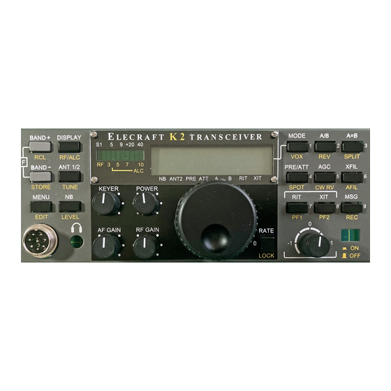
- Page 1 BAND MODE DISPLAY L E C R A F T T R A N S C E I V E R 9 +20 40 RF/ALC SPLIT RF 3 BAND ANT 1/2 PR E/ATT XFIL NB ANT2 PRE ATT STORE TUNE SPOT KEYER CW RV...
- Page 2 T r a n s c e i v e r Owner’s Manual Revision E, February 16, 2003 Copyright 2003 Elecraft, All Rights Reserved Elecraft • www.elecraft.com P.O. Box 69 • Aptos, CA 95001-0069 (831) 662-8345 • Fax: (831) 662-0830...
-
Page 3: Table Of Contents
RF BOARD......................................32 FINAL ASSEMBLY..................................... 75 OPERATION......................................78 CIRCUIT DETAILS.................................... 1 OPTIONS......................................110 PARTS LIST.....................................APPENDIX A SCHEMATIC.....................................APPENDIX B BLOCK DIAGRAM..................................APPENDIX C PHOTOGRAPHS..................................APPENDIX D TROUBLESHOOTING................................APPENDIX E PARTS PLACEMENT DRAWINGS............................APPENDIX F 100-WATT STAGE AND RS232 I/O (K2/100) ............APPENDIX G (SUPPLIED WITH KPA100 OPTION) -
Page 4: Introduction
The basic K2 operates on 80-10 meter CW, and provides over 10 A unique feature of the K2 is that it provides its own built-in test watts of RF output. If you prefer a full-power station, you can... - Page 5 You must send the unit at your expense to Elecraft, but we request replacement parts. Please use e-mail when possible; this will pay return shipping. gives us a written record of the details of your problem.
-
Page 6: Specifications
Frequency control PLL synthesizer w/single VCO covering 6.7-24 MHz in 10 bands; The K2 can receive well outside the indicated bands, but this extended fine steps via DAC-tuned reference range is not specified or guaranteed Transmit ranges may be limited for export to some countries. - Page 7 LECRAFT Transmitter Receiver Preamp On Preamp Off Power output range <0.5 W to >10 W (typ.); Sensitivity (MDS) -135 dBm -130 dBm power setting resolution 0.1 W, -order intercept 0 to +7.5 accuracy 10% @ 5 W -order intercept Min. supply voltage 9.0 V min for 2 watts out Dynamic range, recommended...
-
Page 8: Preparation For Assembly
As shown in Figure 3-2, there are three printed circuit boards This concept extends to the chassis (Figure 3-1). Any chassis (PCBs) in the basic K2 kit: the Front Panel board, Control Board, element can be removed during assembly or troubleshooting. (Also and RF board. - Page 9 LECRAFT Board-to-board Connectors The circuit boards in the K2 are interconnected using board-to-board connectors, which eliminates nearly all hand wiring. Gold-plated contacts are used on these connectors for reliability and corrosion resistance. Figure 3-3 shows a side view of the PC boards and board-to-board connectors. As can be seen in the drawing, the Front Panel board has a connector J1 which mates with right-angle connector P1 on the RF board.
-
Page 10: Unpacking And Inventory
For example, in step 3 you’ll put the modules Identifying Capacitors together for the first time, allowing you to try out the K2’s built-in frequency counter. The counter will then be used in step 4 to align Small-value fixed capacitors are usually marked with one, two, or and test the receiver and synthesizer on 40 meters. - Page 11 BLACK would have a value of 27 µH. Blue x 1M Violet Tools Gray White The following specialized tools are supplied with the K2: Silver x .01 Gold x 0.1 .050" (1.3 mm) Allen Wrench, short handle 5/64" (2 mm)
- Page 12 Magnifying glass Bottom-Mounted Components Conductive wrist strap A number of components in the K2 are mounted on the bottom of Assembly Notes the PC boards to improve component spacing or for electrical reasons. Component outline symbols are provided on both sides of each board, so it will always be clear which side a particular component goes on.
- Page 13 If in doubt about a particular repair, ask for advice from Elecraft or from a someone else with PCB repair experience. The printed circuit boards used in the K2 have circuitry on both Our e-mail reflector is also an excellent source for help.
-
Page 14: Control Board
LECRAFT 4. Control Board The Control board is the "brain" of the K2. It monitors all signals during receive and transmit, and handles display and control functions via the Front Panel board. The microcontroller, analog There are five sizes of 4-40 machine screws provided with and digital control circuits, automatic gain control (AGC), and audio the kit. - Page 15 LECRAFT Assembly Solder all of the resistors, then trim the leads as close as possible to the solder joints. Some builders prefer to trim the leads before soldering. Either method can be used. The side of the Control board with most of the components is Locate RP6, a 5.1 k, 10-pin resistor network.
- Page 16 LECRAFT Install the diodes listed below, beginning with D1, which is in Install and solder the electrolytic capacitors listed below, the upper left-hand corner of the PC board. (Refer to the parts list which are polarized. Be sure that the (+) lead is installed in the hole if necessary to identify the different types of diodes.) If a diode has marked with a "+"...
- Page 17 LECRAFT Install Q12 near the upper left-hand corner of the PC board. Align the large flat side of Q12 with its PC board outline as in Figure 4-2. The body of the transistor should be about 1/8" (3 mm) above the board; don’t force it down too far or you may break the leads.
- Page 18 J1 and J2, which are labeled on the top side of the board. These connectors are provided with the KAF2 audio filter option. You should not install J1 and J2 or the KAF2 option until after K2 assembly and checkout have been completed.
- Page 19 LECRAFT Top side of PC Board The connectors along the bottom edge of the board (P1, P2 and P3) will be installed next. It is very difficult to remove them once they are soldered. Follow all instructions carefully. Hold the Control board vertically as shown in the side view below (Figure 4-7).
- Page 20 LECRAFT Bend two of U2’s corner pins out slightly on the bottom of the board to hold the IC firmly in place, flat against the top of the Before handling any IC, touch an unpainted, board. Find pin 1 and verify that its pad is either round or oval. grounded metal surface or put on a conductive wrist-strap.
-
Page 21: Visual Inspection
(KAF2). This option should be installed Perform the resistance checks listed below to ensure that there only after the basic K2 kit has been completed and tested. are no shorts in the most critical control circuits. (The Control board will be fully tested in a later section.) -
Page 22: Front Panel Board
Locate the front panel PC board, which is just a bit larger than four legs of each switch are centered in their holes, then gently the Control board. It is labeled "K2 FP" on the top side, in the push each switch until it is resting flush against the switch-spacing lower right-hand corner. - Page 23 PC board order. Solder the resistors after all have been installed. (R13 and a few other parts are part of the SSB adapter option, and are not included in the basic K2 kit. A check- Install PN2222A transistors at Q1 and Q2, near the middle of list of these components is provided at the end of this section.)
- Page 24 3/16" (4.8 mm) long pan-head machine screws. will interfere with final front panel assembly. Also, any misalignment will be visible from the front of the K2. Locate the bargraph LED, DS2. The bargraph has a beveled corner or edge that indicates pin 1. Install DS2 as shown by its PC board outline, just to the left of the LCD.
- Page 25 LECRAFT Install another 3/16" (4.8 mm) diameter x 1/4" (6.4 mm) long Install the audio-taper potentiometer, R3, in the lower left- round standoff on the top of the PC board, on the left side of the hand corner. (The PCB is labeled "AUDIO" at R3.) Push only large square hole in the middle of the board.
- Page 26 LECRAFT Install rectangular gray key caps on S1 and S3 so the key caps are parallel to the long axis of the PC board (Figure 5-8). The caps are installed simply by pressing them onto the switch plungers. Gray keycaps diffuser Square Keycap spacers (2)
- Page 27 LECRAFT Examine the backlight assembly closely to ensure that it is The LCD must be seated flat against the diffuser as shown in parallel to the Front Panel board and seated as far down on the the edge view (Figure 5-11). If the LCD does not appear to be board as it will go (exactly 1/8"...
-
Page 28: Uninstalled Components
LECRAFT Uninstalled Components Resistance Checks Check off each of the components in the list below, verifying Set all potentiometers to their mid-points (approx.). that they are not yet installed. Perform the resistance checks (to ground) listed below. U1 is on the back of the board. __ C4, .01 (103) __ C5, .01 (103) __ C6, .01 (103) - Page 29 LECRAFT Front Panel Final Assembly Locate the green plastic bargraph filter and two pieces of double-backed tape. These items will be found in a small bag. Locate the front panel chassis piece. Place it on a soft cloth to protect the finish and labeling. Caution: The adhesive on the double-backed tape is very strong.
- Page 30 LECRAFT Remove the brown paper backing from the other side of each Turn the front panel face up. piece of tape, then turn the filter/tape assembly adhesive-side down. Position the clear plastic LCD bezel over the LCD and Carefully center the green plastic filter over the inside of the bargraph holes as shown in Figure 5-15.
- Page 31 LECRAFT Remove the insulation from four 1.5" (38 mm) lengths of Insert the front panel PC board assembly into the front panel. green hookup wire. The pushbutton switch caps on both sides of the LCD should protrude slightly as shown in the side view, Figure 5-17a. Install the bare wires on the bottom of the front panel PC board, using the four pads below the large rectangular hole (Figure Note: the board/panel assembly will not be rigidly held in place...
- Page 32 LECRAFT Attach the encoder to the inside of the front panel using the Attach small knobs to the potentiometer shafts, starting with nut and flat washer only. Figure 5-18 shows the side view (a) and the KEYER and POWER controls. Each knob's two set screws can front view (b) with encoder properly installed.
- Page 33 For example, "front-left" means the corner closest to you on the left. Part II: Synthesizer and receiver components are installed and tested. By the end of Part II you’ll have the K2 receiving on 40 meters. Part III. Transmitter components and all remaining filter...
- Page 34 LECRAFT Take a moment to familiarize yourself with the RF board using Turn the board over and install 2-D fasteners at five locations Figure 6-1 to identify the major sections. If you flip the board over on the bottom of the RF board as shown in Figure 6-3. Secure each you’ll see that there are a few components on the bottom of the fastener from the top side of the board using two chassis screws board, primarily in the transmitter section.
- Page 35 LECRAFT Make sure that the 2-D fasteners on the edges line up with the Install R1 and R2 (220 ohms, RED-RED-BRN), near the back edge of the PC board and do not hang over. If they hang over or do left corner of the board.
- Page 36 LECRAFT Install D8 and D18 (1N4148), on the bottom of the board, Install the self-resetting fuse, F1, near D10. F1 is yellow and toward the right edge. Make sure the banded end of each diode is looks like a square-bodied capacitor. One side is labeled "G300". aligned with the band on its component outline.
- Page 37 LECRAFT Position 20-pin male right-angle connector P1 on the bottom of the board (Figure 6-5), but do not solder P1 yet. Review Figure Before handling U1, touch an unpainted, grounded 3-3 (page 8) for correct placement. The short ends of the bent metal surface or put on a conductive wrist-strap.
- Page 38 LECRAFT When working with the side panels in the following steps, place a soft cloth on your work surface to protect the paint. Locate the two side panels. Remove any masking tape from Holes offset the panels using the same technique described in the Front Panel away from section, taking care not to scratch the outer surfaces.
- Page 39 Locate the tilt stand, which can be found in the MISCELLANEOUS component bag. It has three parts: two oval Since the K2 chassis is made up of a number of individual feet and a tilt bail (Figure 6-9). Note: the screws that will be used to panels and fasteners, you may need to loosen the fasteners and hold the tilt bail in place are not the black anodized type.
- Page 40 LECRAFT Turn the RF board/side panel assembly upside down. Check for any untrimmed component leads on the bottom of the board. Position the bottom cover as shown in Figure 6-10, then secure it using six chassis screws. (The heat sink and rear feet will not be installed until Part III when the transmitter is assembled.) With the entire assembly still upside down or resting on one side panel, plug the front panel assembly into the RF board (Figure...
- Page 41 LECRAFT Plug the Control board assembly into the RF board, with the Once you have tried the Control board extraction technique component side of the Control board facing backwards. (Refer to described above, plug the Control board back in for the tests that the photos in Appendix D.) All three connectors on the Control follow.
- Page 42 Set the controls on the front panel as follows: Turn on the K2 using S1. After about 10 seconds, you should see the default K2 frequency display for 40 meters: 7 1 0 0 . 0 0 c . AF GAIN: midway (12 o’clock)
- Page 43 LECRAFT Turn the K2 off and wait for a few seconds, then turn it back Tap the switch three times. You should hear relays P R E / A T T N on. The display should now show E L E C R A F T for about two switch each time.
- Page 44 Press and hold the switch for 1/2 second to activate the EDIT E D I T It may cause shorts or noise pickup if left inside the K2 during function. (Remember the TAP/HOLD rule: when you HOLD a normal operation switch in, you activate the function indicated by the lower label on the switch.) The display should now show:...
- Page 45 M E N U Trim the leads of the 10 pF axial-lead capacitor down to 1/4" returns you to the normal K2 display. (6 mm). Solder one end to the center conductor of the coax cable. In the following section you’ll activate the C A L F C T R (frequency counter) function.
- Page 46 The connector can only be plugged in one way. tapping the switch. The display will show B A N D + Turn on the K2 and tap to bring up the menu, then M E N U S T P 0 . 6 0 scroll to the C A L menu entry.
- Page 47 Set your DMM for DC volts. Connect the (-) lead of the by using the bargraph LEDs to establish a known current drain. DMM to one of the ground jumpers or to the K2 chassis ground. Enter the menu and verify that G R P H (LED bargraph mode) Touch the (+) lead to pin 5 of U2 on the Control board.
- Page 48 LECRAFT __ R9, 100 k (BRN-BLK-YEL) ⇒ __ R16, 100 k (BRN-BLK-YEL) Assembly, Part II __ R10, 470 (YEL-VIO-BRN) __ R31, 10 k (BRN-BLK-ORG) __ R32, 10 k (BRN-BLK-ORG) __ R33, 15 k (BRN-GRN-ORG) In this section you’ll install the components for the synthesizer __ R30, 120 (BRN-RED-BRN) __ R28, 27 k (RED-VIO-ORG) __ R20, 270 (RED-VIO-BRN)
- Page 49 MV209 and type 1SV149. (1SV149 diodes are labeled "V149" and may have a center lead that has been cut flush with the body of the device.) The K2 will not function correctly if the Install Q21 (2N5109), which is located near U1 in the middle varactor diode types are interchanged.
- Page 50 __ C153, 68 (68) __ C155, .01 (103) __ C172, .01 (103) "ELECRAFT" label at the middle of the board. Make sure that Z6 is lined up with its component outline and is flush with the board __ C177, .022 (223)
- Page 51 LECRAFT Locate the crystals used on the RF board: 12.096 MHz (1), In the following steps you’ll install several toroidal 4.9152 MHz for BFO (2) and 4.9136 MHz for crystal filters (7). inductors. Use the number of turns indicated. Do not attempt Do not mix the BFO and filter crystals, which have different to alter the turns to match inductances specified in the parts list.
- Page 52 LECRAFT To wind RFC14, cut a 9" (23 cm) length of #26 red enamel- Do not use adhesives or fixatives of any kind to coated wire, then "sew" the long end of the wire through the core secure toroids to the PC board. Toroids will be adequately held exactly 10 times.
- Page 53 LECRAFT T5’s other winding, 3–4, uses 4 turns of green enamel wire (7", 18 cm). Wind the 3–4 winding on top of the 1–2 winding, interleaving the turns as shown in Figure 6-16. The turns should be secure, not loose. Strip and tin the leads of the 3–4 winding. Note: T5’s 3–4 winding must be wound exactly as illustrated or the VFO will not function correctly.
- Page 54 LECRAFT Transformer T6 is mounted vertically, near the middle of the Clip and untwist the ends of the red/green pairs so that the board. It uses a different winding technique where the wires for the leads of the transformer look like those in Figure 6-19 (b). The pin two windings are twisted together before winding ("bi-filar").
- Page 55 LECRAFT __ C133, 0.1 (104) (bend body down before soldering) Review Figure 4-2 before installing Q2 in the next step. Q2 is a ZVN4424A transistor, which has a slightly modified TO-92 __ C135, .01 (103) __ C122, 56 (56) __ C119, .01 (103) package.
- Page 56 LECRAFT R116 The BFO toroid, L33, is supplied pre-wound due to the large number of turns and very small gauge wire required. When handling L33, be very careful not to damage the leads. Locate the rubber stem bumper. Clip off about one-half of the tip of the stem using diagonal cutters.
- Page 57 LECRAFT Visual Inspection It is very important to re-assemble the chassis as described below before attempting the alignment steps in the next section. If Examine the bottom (solder side) of the RF board carefully for you don’t put the chassis together, some alignment results will not unsoldered pins, solder bridges, or cold solder joints.
- Page 58 MHz range. It may or may not be stable at this time (i.e., the end near the 4 MHz crystal on the K2 Control board. Find the frequency may be changing). If the reading is 0000 kHz or is oscillator signal on the receiver.
- Page 59 7300 ______ Disconnect the internal frequency counter probe and remove 30 m 10000 ______ 10150 ______ it completely from the K2. 20 m 14000 ______ 15000 ______ Select 80 meters, and set the VFO for about 4000 kHz. 17 m...
- Page 60 RF board near the crystal filter. If you didn't calibrate the K2's internal frequency counter using Using the menu, select C A L F C T R . The counter should show an external counter, it may not be reading accurately.
- Page 61 The K2 uses a variable-bandwidth crystal filter, allowing the operator to set up as many as four filter bandwidths for each Allow the K2 to stabilize for at least 10 minutes at room operating mode. Each of these filter configurations requires an temperature (approx.
- Page 62 7000 kHz. If you can't hear the signal at all, you may This will allow you to align and test the K2 on all bands. have a receiver problem. Try the 40-meter Band Pass Filter Alignment, below, then refer to Troubleshooting if necessary.
- Page 63 LECRAFT Install the following 1/4-watt resistors, starting with R46 __ C219, 12 (12) __ C138, .047 (473) __ C222, 100 (101) which is just to the left of I/O controller U1. __ C221, 39 (39) __ C220, 220 (221) __ C214, 68 (68) __ C213, 33 (33) __ C212, 150 (151) __ C203, 47 (47)
- Page 64 Install electrolytic capacitors C126 (47 µF) and C137 and the 1 µH inductors are labeled "T1050." (100 µF), Near the "ELECRAFT" label at the center of the board. Insert the (+) lead of each capacitor into the hole marked (+).
- Page 65 LECRAFT TO-220 package transistors Q6, 7, and 8 look identical, but It is very important to wind and install toroidal Q6 is different. Locate the two 2SC1969’s (labeled "C1969"), Q7 transformers T1 through T4 exactly as described in the following and Q8, and set them to one side.
- Page 66 LECRAFT T2 is wound on the same core type as T1 (FT37-43). Its Wind the twisted wires onto a 1/2" (12.7 mm) dia. ferrite core windings must be spaced as shown in Figure 6-26(a), with the 3-4 (FT50-43), using exactly 5 turns and covering about 85% of the core.
- Page 67 LECRAFT Locate the "binocular" (2-hole) ferrite core for T4. Wind 2 Before installing T4, verify that the screws holding the 2-D turns of green-insulated hookup wire (5", 13 cm) through the fastener beneath it are tightened, and that #4 internal-tooth lock core as shown in Figure 6-28.
- Page 68 LECRAFT Place Q7 on the bottom of the board so that the leads are inserted into the PC board as indicated by Q7’s component outline. The mounting screw and hardware should appear as shown in Figure PA transistors Q7 and Q8 (2SC1969) must be installed on 6-31.
- Page 69 Do not remove the option bypass jumpers (W1, W2, etc.). installation of J12 and the standoff. Do not remove W5, R88, The K2 must be aligned and tested before the jumpers are R89 or R90 at this time. removed and option modules installed.
- Page 70 PA transistor hardware as needed. Turn the K2 up on its left side. This will keep the PA transistor screws from slipping out during the following steps. Remove the 4-40 nuts and #4 lock washers from the mounting screws for Q7 and Q8, but do not pull the screws out.
- Page 71 LECRAFT Keeping the K2 on its left side, slip the heat sink over the Secure Q7 and Q8 on the bottom of the heat sink using 4-40 rear-panel connectors and into position (Figure 6-33). Figure 6-34 nuts and #4 lock washers. Do not over-tighten the nuts, as this may...
- Page 72 Refer to the Operation section for details on this "auto- power output). detect" feature (Page 92). Turn on the K2. You should see E L E C R A F T on the LCD, To verify that the sidetone is functioning, hold the followed by the frequency display.
- Page 73 Enter tune mode again and adjust L2 for maximum output. Tap any switch to exit. The K2 transmitter is most efficient at 10 watts and higher; current drain at 5 watts CW may be higher than expected. This is unavoidable because the K2 is capable of up to 15 W output.
- Page 74 During receiver alignment, you may have noticed that signal strength is somewhat lower in volume when you select the narrowest filter (100 Hz setting, FL4). This is because the K2's crystal filter is optimized for wider bandwidths (250-800 Hz). Despite the slightly greater attenuation, the narrower settings are very useful in reducing QRM (interference) from strong, nearby signals.
- Page 75 LECRAFT Transmitter Alignment Since some inductors are shared between two bands, you If you did the receiver alignment, above, you may find that little or must always align the remaining bands in the order indicated. no transmit adjustment is required on most bands. Always use this procedure if you re-align the filters later.
-
Page 76: Final Assembly
LECRAFT 7. Final Assembly Place the top cover upside down as shown in Figure 7-1, with Trim the supplied grille cloth to the size of the speaker frame. its rear panel facing away from you. The illustration shows how the Place #4 fibre washers (black) at each of the top cover's four speaker, 2-conductor cable, external speaker jack and other speaker mounting holes (Figure 7-1). - Page 77 LECRAFT Using a sharp tool, cut through and peel off about 1/2" x 1/2" (12 x 12 mm) of the masking material covering the EXT SPKR hole. Note: Leave the other holes covered with masking material Ground until the associated options are installed. Install the external speaker jack in the EXT SPKR hole.
- Page 78 S1. The connector is keyed and can only be plugged in one way. Even if you have purchased some K2 options, you should not assemble and install them yet. The option manuals assume that you are familiar with basic K2 operation.
-
Page 79: Operation
RF 3 BAND ANT 1/2 PRE/ATT XFIL NB ANT2 PRE ATT STORE TUNE SPOT KEYER POWER CW RV AFIL MENU EDIT LEVEL AF GAIN RF GAIN RATE LOCK NUMERIC RIT/XIT KEYPAD (0) OFFSET POWER MICROPHONE ON/OFF JACK K2 FRONT PANEL... - Page 80 ANTENNA TUNER XVTR ANTENNA 12VDC RCV. ANT. 50Ω LECRAFT SER. NO. KEYER PADDLE, EXT. KEYER, OR HANDKEY 12V BATTERY OR MAIN ANTENNA SEPARATE RECEIVE POWER SUPLY (DO NOT USE IF ANTENNA (PART OF ATU IS INSTALLED) 160M/RXANT. OPTION) K2 REAR PANEL...
- Page 81 Any type of hand key, bug, or external keyer can be plugged into the settings or with high SWR. (See Current Limiting, below.) KEY jack, or you can use the K2's built-in memory keyer. In all cases, you must use a stereo plug with the keying device (a suitable Internal Battery: An optional 12 V, 2.9-Ah rechargeable...
-
Page 82: Controls And Display
When you turn this control, power output will be displayed in watts, pre-amp on (approx. +14 dB) e.g. P 5 . 0 . The range is 0.1 to 15 W for the basic K2, and 1 to ATTN attenuator in (-10 dB) 100 W if you have the KPA100 amplifier installed. -
Page 83: Switch Functions
LECRAFT turn on preamp or attenuator Switch Functions P R E / A T T CW audio spot signal on/off S P O T Each pushbutton switch as two primary functions, indicated by the turn on RIT (see R I T menu entry, page 101) R I T upper and lower labels. -
Page 84: Using The Menu
LECRAFT Using the Menu Primary Menu Functions There are two menus: primary and secondary. You'll use the All primary menu functions are listed below (secondary menu primary menu far more often; see list at right. The secondary functions are listed on page 100). Supplemental parameters accessed menu is described starting at page 100. -
Page 85: Circuit Details
LECRAFT To set the S-meter sensitivity: Calibration Functions 1. disconnect the antenna The C A L menu provides the following functions: 2. turn the RF GAIN control fully counter-clockwise (minimum gain) F C T R frequency counter 3. select C A L S H I in the menu C U R programmable transmit current limit 4. - Page 86 E D I T from CW normal to CW reverse. Whenever you switch modes or filters, the K2 will first record your new settings, if they have been Filter Bandwidth Display changed. The initial C A L F I L display shows the present filter bandwidth...
- Page 87 Table 8-1 shows the recommended filer settings for a CW-only knob to select the value shown in the table. Typically you'll be K2. If you already have the SSB adapter installed, use the SSB able to get to within +/- 20 Hz of the target frequency.
- Page 88 Attenuator: If necessary, an additional 10 dB of attenuation can be switched in by turning on the attenuator. This is more effective Sideband Inversion: The K2 inverts the sideband on 15 meters than using the RF GAIN control in the case of strong-signal and above due to the frequency mixing scheme (the upper and lower overload.
- Page 89 Frequency and Band Selection Day/Night Selection: If you're operating outdoors, use the menu The basic K2 kit covers the 80 through 10 meter bands. 160 meter to select L C D D A Y , which turns off the LCD backlight and puts coverage can be added with the K160RX option, and 60 meters the bargraph into high-brightness mode.
- Page 90 8400 kHz--which is typically band memories, respectively. outside the range of the synthesizer--the K2 will switch to 40 meters and setup the VFOs as they last were on this band. Store and Recall: Ten memories are provided, numbered 0 through 9.
-
Page 91: Power Control
C A L C U R (see Calibration previously.) Functions). You can install an LED on the front panel that will turn on whenever SPLIT, RIT, or XIT is in effect. See the associated application note, Adding a SPLIT/RIT/XIT LED to the K2. - Page 92 VFO frequencies with RIT on and off. relays, etc. Note: If you have both a KAT2 and a KAT100 connected to your K2, the A T U menu entry will control only the When is turned on, it works similarly to...
- Page 93 "tip" contact (DOT) of the key jack with a hand key or external Auto Detect can be turned off if desired. Find the I N P menu entry, keying device. You can key the K2 externally at up to 70 WPM. to select A D E T O F F .
- Page 94 LECRAFT Basic CW Setup The SPOT Switch Mode Selection: To place the rig in CW mode, tap the switch can be used to zero-in on received signals or to M O D E S P O T test your sidetone pitch quickly, without having to key the switch until the mode indicator changes to C.
- Page 95 HOLD rather than TAP the numbered switch (i.e., use # directly to the K2's key jack. Set I N P to P D L n or P D L r . Chaining is useful during contests. For example, you might set up message 5 as "QSL 73"...
-
Page 96: Ssb Operation
You’ll need to configure the MIC CONFIG header on the Front adapter installed. Basic information on using the SSB adapter is Panel board in order to transmit SSB on the K2. Most microphones provided here. For complete details, refer to the KSB2 manual. -
Page 97: Advanced Operating Features
RF GAIN control. Also try using a narrower filter or turning off the preamp. You'll The K2's scanning feature lets the K2 tune any band segment need to re-store the scan memory after making these changes. - Page 98 LECRAFT Reducing Current Drain for Portable Operation Programmable Function Switches (PF1/PF2) You can use any of the methods listed below to reduce receive- switches (below , respectively) can P F 1 P F 2 R I T X I T mode current drain and thus extend battery life.
- Page 99 TP1). You'll also need to use C A L F I L (with the probe on TP2) You can check the K2's main microcontroller and I/O to re-adjust each BFO setting, which will allow the K2 to store new, controller firmware revisions by holding in any switch on power- more accurate BFO frequency measurements.
- Page 100 • secondary menu parameters, if applicable To use FINE RIT: Select a narrow data-mode filter (F L 2 - F L 4 ) To reset to defaults: Turn the K2 off, then hold down the using . Next, hold together; the display will...
- Page 101 Accessory output control Fast-Play CW Messages (FPLY) D 1 9 Leave at default (n ) unless K60XV option installed K2/100 final stage mode selection (Fan Mode*) CW messages are normally played by tapping , then M S G T R N 1 - 3...
- Page 102 H i ). For more details, refer to the KPA100 manual (Appendix G of modify the r -mode filter bandwidths or BFO settings as needed. the K2 owner's manual, which is supplied with the KPA100 kit). Speech compression (S S B C r ): The S S B C menu entry will change to S S B C r when r mode is selected.
- Page 103 O F S Display offset (+/- 9.99 kHz); calibrate MHz and a 1.0-watt power limit. If you switch the K2 to 14 MHz-- based on transverter oscillator offset, if any where there is no power limit--you must remember not to transmit...
-
Page 104: Circuit Details
(An alternative is up-conversion followed directly by a product detector and audio filter. While The K2’s custom enclosure is also modular. It is fabricated in six pieces, this results in minimal parts count, it was not considered since the resulting with a unique 2-D fastener used at each joint and also for PCB support. - Page 105 4915.0 4915.5 The signals you tune in on the K2's receiver are "shaped" by the crystal filter, which passes only a narrow range of frequencies. The pitch of these signals is determined by the BFO (beat-frequency oscillator). Figure 9-1 shows an example of how these signals are related.
- Page 106 OFF, DOT or BAR mode for the bargraph, with OFF or DOT modes the transceiver itself. It also reduces cost of the basic K2, since fewer main- typically used to save current during battery operation. U3 and U4 are 8- processor control lines are needed.
- Page 107 To get the most out of the available I/O on the MCU, much of the Offset) are multiplexed onto a single A-to-D input of the MCU, the communication from MCU to the rest of the K2 is done via serial interfaces: "VPOTS" line, so their position can be read. Firmware hysteresis is used for...
- Page 108 RF Board milliohms, is located on the RF board (R115). The RF board is the largest of the three K2 boards, and serves as a structural U4 is a low-dropout 8 V regulator, which is stable with a K2 input DC element that the chassis and the other boards attach to.
- Page 109 U11 also provides the BFO signal, which is tunable over about a 4 to 5 kHz which is designed to protect the K2 and its power supply from almost any range by varactor diodes D37 and D38. X3 and X4 have carefully-controlled conceivable mis-connection or short.
- Page 110 LECRAFT Sheet 3: Filters and I/O Controller The latching relays are wired with a single common drive line so that when one relay needs to be turned on or off, the others are pulled in the opposite The band-pass and low-pass filters are switched with latching relays to direction.
-
Page 111: Options
10 LEDs for real-time monitoring of SWR. Note: The cover reinstalled, when low-power field operation is planned. KAT100 can be used with the basic K2 as well as the K2/100. The basic K2 must have the KIO2 option installed to control the tuner. - Page 112 Bag, Control Parts Control board parts E850002 Bag, Misc. Parts Hardware and Misc. parts E850004 K1, K2, K3, K4, K5, K6, K7, K8, K9, K10, K11, K12, K13, K14, K15, K16, K17 Latching Relay, 5V In plastic tube; 10-pin DIP E640001...
- Page 113 Appendix A Items inside back of manual E850011 PICTURE Designators Value Description Part Number Covers LCD and LED bargraph (FRONT Misc Acrylic display bezel PANEL) E100080 Thermal insulator, Adhesive Thermal Insulators for Q6, Q7, Q8 TO220 (RF BOARD) E700002 Serial Number Label E980010 1.15”...
- Page 114 Appendix A Appendix A K2 Control Board Parts List (p/n E850002) PICTURE Designators Value Description Part Number C2, C20, C34, C43 .001 Monolithic Cap, "102" E530001 C12, C24, C36 .0027 Monolithic Cap, "272" E530055 C3, C5, C9, C10, C11 C17, C18, C23, C35, C37, C39, C40, C41 Monolithic Cap, "103"...
- Page 115 Appendix A Appendix A K2 Control Board Parts List (p/n E850002) PICTURE Designators Value Description Part Number 6P male, RA Right Angle 6 pin connector E620041 18x2 male, RA Right Angle 18 x 2 pin connector E620043 10x2 male, RA...
- Page 116 Appendix A Appendix A K2 Control Board Parts List (p/n E850002) PICTURE Designators Value Description Part Number 50K Trimmer AGC Threshold E520011 470,5R ISO "10A3- SIP resistor pack, 10 pins; ALT: 471G" "770103471" E510015 3.9K,5R ISO SIP resistor pack, 10 pins; ALT: "770103392"...
- Page 117 Appendix A Appendix A K2 Control Board Parts List (p/n E850002) PICTURE Designators Value Description Part Number Crystal, HC49 (may be standard or low- 5.068Mhz profile) E660009 4.000MHz Crystal, HC49 (standard) E660006 MISC 40 pin socket socket for MCU E620017...
- Page 118 Appendix A K2 Front Panel Board Parts List (p/n E850003) PICTURE Designators Value Description Part Number C1, C3 .047 Monolithic, "473" E530025 C2, C9 Monolithic, "103" E530009 D2, D3 LCD Backlight Assy LED Backlights mounted in Diffuser E570004 D4, D5, D6...
- Page 119 Appendix A K2 Front Panel Board Parts List (p/n E850003) PICTURE Designators Value Description Part Number Misc Keycap, rect, black Black keycaps for Push Buttons ( BLACK) E980000 Misc Keycap, rect, gray Band up/down keycap; S1, S3 (GRAY) E980027 Misc Keycap, square, black Rate / Lock Keycap;...
- Page 120 Appendix A K2 Front Panel Board Parts List (p/n E850003) PICTURE Designators Value Description Part Number S1, S2, S3, S4, S5, S6, S7, S8, S9, S10, S11, S12, S13, S14, S15, S16 switch, push button Front Panel push button switches...
- Page 121 Appendix A K2 RF Board Parts List (p/n E850001A and E850001B) PICTURE Designators Value Description Part Number C1, C2, C9, C17, C26, C27, C37, C38, C39, C49, C57, C64, C77, C79, C80, C81, C82, C89, C91, C100, C140, C167, C195, C204, C207, C208, C216, C223 .001...
- Page 122 Appendix A K2 RF Board Parts List (p/n E850001A and E850001B) PICTURE Designators Value Description Part Number C221 NPO, "39" or "390" E530036 C20, C24, C73, C203 NPO, "47" or "470" E530014 C31, C35, C122, C228 NPO, "56" or "560"...
- Page 123 Appendix A K2 RF Board Parts List (p/n E850001A and E850001B) PICTURE Designators Value Description Part Number ceramic trimmer (see below to tell from 50 C44, C46, C32, C34 var,5-30pF E540001 ceramic trimmer (red mark or bagged C21, C23 var,8-50pF...
- Page 124 Appendix A K2 RF Board Parts List (p/n E850001A and E850001B) PICTURE Designators Value Description Part Number 6p,female socket 6 x 1 female socket E620037 Antenna connector E620020 Keyer Jack, Threaded, Stereo, Vertical SJ-373 orientation E620027 Stereo+iso sw. Headphone jack. Horizontal Orientation E620028 Variable Ind, 1µh...
- Page 125 Appendix A K2 RF Board Parts List (p/n E850001A and E850001B) PICTURE Designators Value Description Part Number 10µH , Shielded solenoidal, shielded, DELEVAN (BLACK) E690005 Pre-wound toroidal FRAGILE LEADS--HANDLE WITH CARE. inductor, 41 µH, 5%, SEE TEXT FOR MOUNTING T44-7 core INSTRUCTIONS USING 1/8W RESISTOR E690018 Toroid (BLACK);...
- Page 126 Appendix A K2 RF Board Parts List (p/n E850001A and E850001B) PICTURE Designators Value Description Part Number Binocular core 2:3:1:1, Balun Core; Square, Two Holes E690011 2 (GRAY) ferrite beads ea. on bare wire Z1, Z2 Ferrite Bead (see text)
- Page 127 Appendix A K2 RF Board Parts List (p/n E850001A and E850001B) PICTURE Designators Value Description Part Number Q10, Q12, Q17, Q20, Q23 2N7000 TO-92 E580002 Q18, Q19, Q24 J310 TO-92 E580012 Q11, Q13, Q16, Q25 PN2222A TO-92 E580001 ZVN4424A Slightly Thinner TO-92 Style...
- Page 128 Appendix A K2 RF Board Parts List (p/n E850001A and E850001B) PICTURE Designators Value Description Part Number R75, R80 (TAN) E500040T R91, R93, R100 (TAN) E500001T R38, R39 (TAN) E500013T R79, R81 1.8K (TAN) E500004T R5, R19, R24, R25, R34, R44, R62, R66, R73, R95, R96 2.7K...
- Page 129 Appendix A K2 RF Board Parts List (p/n E850001A and E850001B) PICTURE Designators Value Description Part Number U3, U9 LT1252 8 pin DIP, VFO Buffer; TX Buffer E600020 8 pin DIP, 12-Bit DAC for Reference Freq. LTC1451 Of PLL E600016 LMC662 8 pin DIP, (rail-to-rail out);...
- Page 130 Appendix A K2 RF Board Parts List (p/n E850001A and E850001B) PICTURE Designators Value Description Part Number DPDT Power Switch E640006 MISC Keycap; TAC-BLK Power Switch Keycap; rectangular E980023 MISC 28 pin socket, 0.3" DIP Socket for U1 E620011 heatsink TO5 Flush Crown heatsink;...
- Page 131 Appendix A K2 Misc. Bag Parts List (p/n E850004) PICTURE Designators Value Description Part Number QTY #4 lockwasher internal tooth E700010 2-56,screw , 1/8", fillister head, STAINLESS 2-56 x 1/8”,slotted, STAINLESS for LCD bezel E700023 2-D Fastener Chassis fasteners E100078...
- Page 132 Appendix A K2 Misc. Bag Parts List (p/n E850004) PICTURE Designators Value Description Part Number QTY 2 pin female conn. SPK-J1 Housing 0.1” spacing w/locking ramp, int. speaker plug E620021 ACC-P1 2.1mm male conn. Mates with DC power jack E620032 ACC-P2 stereo 1/8”...
- Page 133 Appendix A K2 Misc. Bag Parts List (p/n E850004) PICTURE Designators Value Description Part Number QTY Appendix A K2 Probe Assemblies Parts List (p/n E850036 envelope in E850004 Misc bag) Part Number QTY PICTURE Designators Value Description FCP-C1 10pf cap Axial Leads (like a resistor);...
-
Page 134: Special Symbols
Relay Table Diodes SET Relays MV209, 1SV149 Band 1Nxxxx 160m 160m-K1 K2, K3 +60m K1, 60m-K1 K13, K14 *40m ALT K13, K14 4 0 m K3, K4 K14, K15 Transistors K13, K14, K15 2SC2166 K13, K15 2SC1969 2 N 3 9 0 6... - Page 135 . 0 1 . 0 1 . 0 1 . 0 1 Mic Config. /MIC RD 5K (audio taper) Elecraft K2 Front Panel Board These components are supplied with SSB adapter. Rev. Date Sht. W. Burdick E. Swartz 1 0 / 6 / 0 2...
- Page 136 V AGC 3 3 0 5.1K 5.068MHz To RF Board, J7 To RF Board, J8 I.F. OUT Elecraft K2 Control Board To RF Board, J6 Rev. Date Sht. W. Burdick 2 / 1 6 / 0 3 1 of 1 E.
- Page 137 SB530 C105 2.2µF 2.2µF R 1 1 3 Power 1 4 1 5 2 N 7 0 0 0 K2 RF Board Elecraft Rev. Date Sht. W. Burdick E. Swartz 2 / 1 6 / 0 3 1 of 4...
- Page 138 . 0 0 1 NE602 1 N 4 0 0 7 1 0 0 K 2 7 0 C155 . 0 1 Elecraft K2 RF Board BFO Buffer/Attenuator * Remove C167 when SSB Adapter is installed. TX VFO C144 Rev. Date Sht.
- Page 139 NOTE: Pins 5 and 6 of relays are not connected internally. K 1 6 However, these pins may be connected to other relay pins K 1 7 or to other components on either side of the PC board. Elecraft K2 RF Board C207 C204 Rev. Date Sht.
- Page 140 V BIAS-XFIL PN2222A C137 1 0 0 µ F C138 . 0 4 7 1 0 0 /CLASS AB Elecraft K2 RF Board 2 2 0 Rev. Date Sht. W. Burdick 2.7K 4 of 4 E.Swartz 2 / 1 6 / 0 3...
- Page 141 BAND- POWER LOW-PASS PASS DRIVER FILTERS FILTERS (10W) 4.915MHz ATTEN. POST- CRYSTAL NOISE MIXER I.F. AMP FILTERS MIXER BLANKER PREAMP XMIT BAL. BUFFER MIXER MOD. PROD. DETECTOR MCU AND SUPPORT 6 - 24MHz SYNTH. CIRCUITS 4.915MHz AF AMP Shaft Encoder DISPLAY AND CONTROLS Common...
- Page 142 Check values of R16 and R15 on the front panel When referring to components on the various K2 boards in the table, we will Check continuity from LCD driver (U1) to sometimes use a shorthand form such as “RF-U11,” which means U11 on the LCD.
- Page 143 Disconnect the battery from (025) the K2 and measure its voltage; if the battery If the supply voltage and antenna impedance voltage quickly rises back to 11 or 12V, the are correct, the driver or PA transistors may K2 may be loading the battery down.
- Page 144 If +5V is too low (< 4.5V) go to 052 operating frequency operating the K2; otherwise the VFO cannot If +8V is too low (< 7.5V) go to 053 appears to be entirely be tuned properly and the synthesizer may...
- Page 145 Re-install the front panel board and turn on you lift one end of this inductor it will the K2. Using a voltmeter, measure the disconnect the entire synthesizer from the 8V voltages on pins 16 and 17 of front panel line.
- Page 146 075 Possible MCU Measure the voltage on pin 32 of the MCU 081 AuxBus problem You may have an option board installed that problem (U6, control board). If it is not 5V, check the is causing a problem with the AuxBus. Try 5V regulator (052).
- Page 147 Receiver (100-149) 110 AF amp not Use the menu to set a sidetone level of 60 working S T L 0 6 0 ). Hold . If you hear a S P O T strong tone, the A.F. amplifier itself is Problem Troubleshooting Steps probably working;...
- Page 148 Check for any components getting hot Transmitter problem If power output slowly increases during key- Turn the K2 OFF and remove the heat sink; down, go to 160 inspect all parts and check for shorts or opens If current drain on transmit is too high for the...
- Page 149 (oscillating) even when connected to a 50-Ω Operation and Alignment (200-249) load, you may have an incorrect component value or a toroid-winding error; go through Problem Troubleshooting Steps the checks at 155 201 EEPROM I N F O 2 0 1 is an informational message Make sure none of the diodes in the T-R initialized...
- Page 150 An insulated alligator clip is provided for ground (E2). It should be this band. If you have only completed the K2 up through part II of the RF connected to the board using 4" of black insulated hookup wire. Two banana board (40 m), you'll have to use a crystal in the 6.8 to 7.5 MHz range.
- Page 151 The DMM should read close to 0.000 V DC. The reading should increase when you touch the RF probe tip with your finger. Turn on the K2 and switch to 30 m (or the appropriate band for your signal generator). Select CW Normal mode.
- Page 152 BFO (RF, sheet 2) Mixer, I.F. Amplifiers, and Crystal Filter (sheet 2) BFO Output: Measure the signal on U11, pin 6 (NE602). Expected: Attenuator Off Test: Measure the signal at the end of R72 closest to 0.20-0.70 Vrms. Actual: ______. Q21.
- Page 153 AC voltage at pin 5 reads .025 Vrms. (The Transmitter K2’s RF GAIN control should still be at minimum.) The following procedure can be used to isolate problems with the transmitter Disconnect the headphones and speaker. Turn the AF GAIN control to (the transmitter area of the RF board is identified in Figure 3).
- Page 154 This is a safe setting for sidetone tests, since there is no power Set up the K2 for 40 meters (about 7100 kHz), CW Normal mode. output. Plug in a 50-ohm dummy load (10-W or higher rating).
- Page 155 After checking DC voltages and transformer leads, turn off power to the K2 and use your DMM’s Transmit Mixer, Buffer, Band-Pass Filter, T-R Switch (RF, sheets 2-3) diode/transistor test range to test the transistors. With the DMM’s positive lead on the base of Q7, you should measure about 0.6 k to the...
- Page 156 CONTROL BOARD (Front panel removed except ** = CAL FCTR mode w/front Panel plugged in; * = approximate and/or may fluctuate) Ref. Ref. Ref. Ref. Ref. Ref. 0.4* 0.0* 0.2* .02* 5.0* 0.8* .02* 0.2* 2.6* 1.2* 4.7* 0.2* 0-5* 13.7 0-5* 0 or 5...
- Page 157 FRONT-PANEL BOARD (* = approximate and/or may fluctuate; ** = not accessible due to LCD) Ref. Ref. Ref. Ref. Ref. Ref. 0.8* > 0 0.4* > 0 4.0* 2.0* .02* 0.2* 3.1* 0.8* 4.0* 0.2* 3.6* 3.6* 0.1* > 0 >...
- Page 158 RF BOARD (Shaded areas indicate transmit-mode voltage measurements) Ref. Ref. Ref. Ref. Ref. Ref. 0.15 13.8 2 to 3 -1.0 2 to 3 12.4 13.3 13.2 13.4 0 to 4 12.5 13.4 0 to 8 13.7 0 to 4 0 to 4 0 to 8...
- Page 159 Appendix F Parts Placement Drawing, Top...
- Page 160 Appendix F Parts Placement Drawing, Bottom...
Need help?
Do you have a question about the K2 and is the answer not in the manual?
Questions and answers