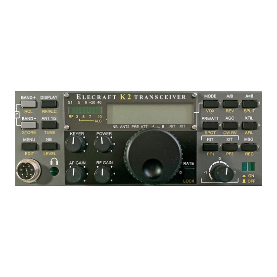
ELECRAFT K2 Instruction Manual
Hide thumbs
Also See for K2:
- Owner's manual (161 pages) ,
- Troubleshooting (3 pages) ,
- Assembly and operating instructions (2 pages)

Related Manuals for ELECRAFT K2


Summary of Contents for ELECRAFT K2
- Page 1 Alignment Instructions Extracted from the K2 Manual By Don Wilhelm W3FPR...
- Page 2 Set your DMM for DC volts. Connect the (-) lead of the DMM to one of the ground jumpers or to the K2 chassis ground. Touch the (+) lead to pin 5 of U2 on the Control board. (U2 is located just above trimmer R1.
- Page 3 Set the receiver for LSB or USB mode. Connect a short length of wire to the receiver's antenna jack, and lay the end near the 4 MHz crystal on the K2 Control board. Find the oscillator signal on the receiver. Tune the receiver to 4.000 MHz, and adjust C22 until you hear a zero-beat (pitch = 0 Hz).
- Page 4 VFO for a frequency of about 4000.10 kHz. Disconnect the internal frequency counter probe and remove Connect the frequency counter probe to the VCO test point, it completely from the K2. TP1. Activate the frequency counter using CAL FCTR as before.
- Page 5 the table by selecting the 1-kHz tuning rate.) BFO Test The BFO (beat-frequency oscillator) will be tested in the Table 6-1. VCO Voltage Readings following Band Low Freq. Voltage High Freq. Voltage steps. 80 m 3500 ______ 4000 ______ 40 m 7000 ______ 7300 ______ Switch to the 40-m band.
- Page 6 Perform the steps in the example on page 86 to set up all filters. You'll use the filter and BFO data from Table 8-1 (for a CW-only K2), since the SSB adapter is not installed. If you later install the SSB adapter, you can easily change the settings to take...
- Page 7 Make sure the bottom cover is securely attached. L34, located near the right front corner of the RF board, is used Allow the K2 to stabilize for at least 10 minutes at room peak the output of the I.F. amplifier.
- Page 8 40-Meter Band Pass Filter Alignment Connect an antenna or a signal generator to the antenna jack on the rear panel. If you use a signal generator, set it for approx. 7150 kHz at an output level of about -100 dBm, or strong enough to activate the S-meter.
- Page 9 The sidetone volume and tone will vary a small amount as the pitch is changed, but it should have a pleasant In this section you’ll complete alignment and test of the K2 on all sinewave sound at any setting.
- Page 10 The output will quickly be reduced to about 2.0 W by the firmware if this happens. Put the K2 into tune mode and activate the built-in wattmeter by holding TUNE. Using the alignment tool, adjust L1 for maximum output.
- Page 11 The K2 transmitter is most efficient at 10 watts and higher; current drain at 5 watts CW may be higher than expected. This is unavoidable because the K2 is capable of up to 15 W output. Also, for a given power level, SSB...
- Page 12 Adjust L3 and L4 for maximum signal strength. narrowest filter (100 Hz setting, FL4). This is because the K2's crystal filter is optimized for wider bandwidths (250-800 Hz). Since some inductors are shared between two bands, you Despite the slightly greater attenuation, the narrower settings are must always align the remaining bands in the order indicated.
- Page 13 maximum power output. Transmitter Alignment Switch to 10 meters (28200 kHz) and adjust L12 and L13 for If you did the receiver alignment, above, you may find that little maximum power output. no transmit adjustment is required on most bands. Switch to 12 meters (24900 kHz) and adjust C44 and C46 for maximum power output.
- Page 14 15 m and above, which may be confusing during filter setup.) 4. Select CW mode using . If a bar appears above the C, MODE the K2 is in CW Reverse mode; hold CW REV to select CW Normal mode. 5. Tap until FL1 is selected. XFIL 6.
- Page 15 CW REV MODE to switch from CW normal to CW reverse. Whenever you switch modes or filters, the K2 will first record your new settings, if they have been changed. switches to the filter bandwidth display, and BAND + BAND –...
- Page 16 Table 8-1 shows the recommended filer settings for a CW-only only K2 K2. If you already have the SSB adapter installed, use the SSB settings from the KSB2 manual. 1. Read the CAL FIL instructions on the previous page if you haven't already.
Need help?
Do you have a question about the K2 and is the answer not in the manual?
Questions and answers