Lika HM58 PS User Manual
Programmable encoder with ssi interface
Hide thumbs
Also See for HM58 PS:
- Mounting instructions (2 pages) ,
- Quick start manual (2 pages) ,
- Manual (2 pages)
Table of Contents
Advertisement
Quick Links
Advertisement
Table of Contents

Related Manuals for Lika HM58 PS


Summary of Contents for Lika HM58 PS
- Page 1 User's guide HM58 PS Programmable encoder Smart encoders & actuators...
-
Page 2: General Contents
Questa pubblicazione è edita da Lika Electronic s.r.l. 2013. All rights reserved. Tutti i diritti riservati. Alle Rechte vorbehalten. Todos los derechos reservados. Tous droits réservés. Il presente manuale e le informazioni in esso contenute sono proprietà di Lika Electronic s.r.l. e non possono essere riprodotte né... -
Page 3: Table Of Contents
General contents User's guide.......................................1 General contents....................................3 Subject Index.......................................6 Typographic and iconographic conventions..........................8 Preliminary information..................................9 1 Safety summary..........................10 1.1 Safety..................................10 1.2 Electrical safety...............................10 1.3 Mechanical safety..............................11 2 Identification............................12 3 Mechanical installation........................13 3.1 Encoder with solid shaft............................13 3.1.1 Customary installation..........................13 3.1.2 Installation using fixing clamps (optional kit code LKM 386)............14 3.1.3 Installation using a mounting bell (optional kit code PF4256)..........14 3.2 Encoder with hollow shaft..........................15... - Page 4 Output type....................................38 Version......................................38 Read parameters..................................38 Load default parameters..............................38 6.3 CONFIGURATION page............................39 6.3.1 POSITION box..............................39 Position.......................................39 Turns......................................39 Counts/rev....................................40 6.3.2 PRESET / OFFSET box............................40 Preset......................................40 Activate preset..................................43 Offset......................................43 Shifted Gray code or Gray Excess code........................44 Activate offset..................................47 6.3.3 DIAGNOSTICS box............................48 No error......................................48 6.3.4 ENCODER CONFIGURATION box......................49 Output code....................................49 Protocol.......................................51...
- Page 5 Attention: the maximum transmitted position requires a SSI clock number greater than the set one ........................................64 Carattere non valido................................64 Counts to be displayed must be lower than the hardware counts of the encoder........65 Error creating the file................................65 Error reading the file................................65 Value higher than the hardware resolution, please set a lower value............65 Value not valid, offset + maximum set position greater than the maximum transmitted position..65 Value not valid: preset greater than the maximum position................65...
-
Page 6: Subject Index
Subject Index No error................47 Number of revolutions...........55 1 – Start teaching............58 Number of shifted bits...........53 2 - Stop teaching.............58 Offset..................42 Output code...............48 Activate offset..............46 Output type................37 Activate preset..............42 Attention: enabling the parity bit......63 Port..................36 Attention: the maximum transmitted position. .63 Position.................38 Positive counting direction..........50 Carattere non valido............63... -
Page 7: Typographic And Iconographic Conventions
In this guide, to make it easier to understand and read the text the following typographic and iconographic conventions are used: parameters and objects both of Lika device and interface are coloured in ORANGE; • alarms are coloured in RED;... -
Page 8: Preliminary Information
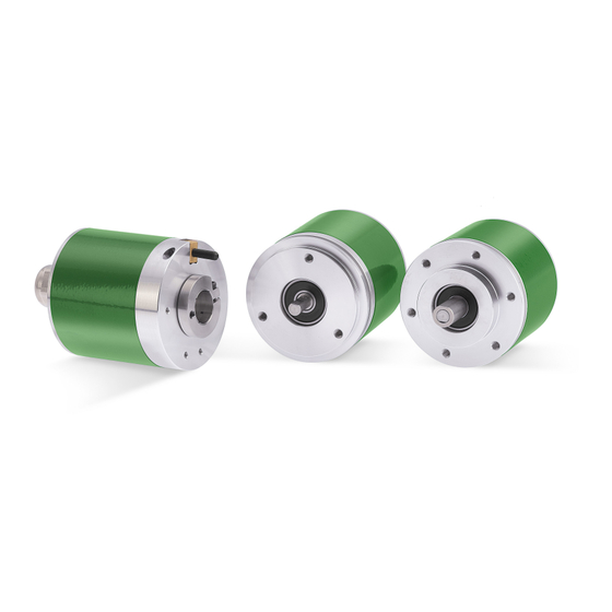
HM58 PS programmable encoder is available in both hollow and solid shaft versions. The parametrization and set up of the HM58 PS programmable encoder is achieved through a software expressly developed and released by Lika Electronic. The program is supplied for free and can be installed in any PC fitted with a Windows operating system (Windows XP or later). -
Page 9: Safety Summary
• elsewhere in this manual violates safety standards of design, manufacture, and intended use of the equipment; Lika Electronic s.r.l. assumes no liability for the customer's failure to comply • with these requirements. 1.2 Electrical safety Turn OFF power supply before connecting the device;... -
Page 10: Mechanical Safety
MAN HM58 PS SSI E 1.0 Safety summary 10 of 72... -
Page 11: Identification
Information is listed in the delivery document too. Please always quote the ordering code and the serial number when reaching Lika Electronic s.r.l. for purchasing spare parts or needing assistance. For any information on the technical characteristics of the product refer to the technical catalogue. -
Page 12: Mechanical Installation
• mount the flexible coupling 1 on the motor shaft; • make sure the misalignment tolerances of the flexible coupling 1 are respected. 3.1.1 Customary installation [mm] [mm] [mm] [mm] HM58 PS 50 F7 HM58S PS 36 H7 MAN HM58 PS SSI E 1.0 Mechanical installation 12 of 72... -
Page 13: Installation Using Fixing Clamps (Optional Kit Code Lkm 386)
In order to guarantee reliability over time of the encoder mechanical parts, we recommend a flexible coupling to be installed between the encoder and the motor shaft. Make sure the misalignment tolerances of the flexible coupling are respected. MAN HM58 PS SSI E 1.0 Mechanical installation 13 of 72... -
Page 14: Encoder With Hollow Shaft
Avoid forcing the encoder shaft; • insert the anti-rotation pin 1 into the slot on the flange of the encoder; this secures it in place by grub screw 2, preset at Lika; • fix the collar 3 to the encoder shaft. -
Page 15: Hmc59 Ps Installation Using The Fixing Plate
Avoid forcing the encoder shaft; • fasten the fixing plate 4 to the rear of the motor using two M3 cylindrical head screws 5; • fix the collar 3 to the encoder shaft. MAN HM58 PS SSI E 1.0 Mechanical installation 15 of 72... -
Page 16: Hmc60 Ps Installation Using The Antirotation Pin And The Fixing Plate
This could cause serious damages to the internal parts and an immediate warranty loss. Please contact our technical personnel for the complete availability of "custom made" shafts. MAN HM58 PS SSI E 1.0 Mechanical installation 16 of 72... -
Page 17: Electrical Connection
: fix min. 25 mm (0.98”) / dynamic min. 45 mm (1.77”) Work temperature : fix -40 +90°C (-40 +194°F) / dyn -50 +90°C (-58 +194°F) Conductor resistance : < 90 /km - < 148 /km MAN HM58 PS SSI E 1.0 Electrical connection 17 of 72... -
Page 18: M23H 12-Pin (Counter-Clockwise) Connector Specifications
1 and then bend it over the part 2; finally place the ring nut 3 of the connector. Be sure that the shielding 1 is in tight contact with the ring nut 3. MAN HM58 PS SSI E 1.0 Electrical connection 18 of 72... -
Page 19: Ground Connection
Counts to be displayed is set; or when the Programming mode: Start / Stop Counts to be displayed option is set; or Programming mode: Prog when the option is set. MAN HM58 PS SSI E 1.0 Electrical connection 19 of 72... -
Page 20: Counting Direction
(and the decreasing count when the encoder is turning counter-clockwise). WARNING After having set the new counting direction it is necessary to set also the preset / offset functions. MAN HM58 PS SSI E 1.0 Electrical connection 20 of 72... -
Page 21: Rs-232 Serial Connection
HM58 PS 4.9 RS-232 serial connection This HM58 PS programmable encoder is equipped with a serial interface for the parametrization and set up of the device. A software tool designed to program the encoder via RS-232 interface is available at the address www.lika.biz >... -
Page 22: Ssi Interface
At the first falling edge of the clock signal (1, the logic level changes from high to low) the absolute position value is stored while at the following rising edge (2) the transmission of data information begins starting from the MSB (Most Significant Bit). MAN HM58 PS SSI E 1.0 SSI interface 22 of 72... - Page 23 The clock signal has a typical logic level of 5V, the same as the output signal which has customarily a logic level of 5V in compliance with RS-422 standard. MAN HM58 PS SSI E 1.0 SSI interface 23 of 72...
-
Page 24: Tree Format" Protocol (Figure 2 And Figure 3)
As you can easily assume, the “Tree format” protocol is not compatible with single-turn encoders having a resolution higher than 13 bits and with multi-turn encoders having an overall MAN HM58 PS SSI E 1.0 SSI interface 24 of 72... -
Page 25: Lsb Right Aligned" Protocol (Figure 4, Figure 5 And Figure 6)
CONFIGURATION page (see on ALIGNED next to the parameter page 50); it is set as a default in the HM58 PS programmable encoder. It allows to right align the data bits, beginning from MSB to LSB; LSB is then sent at the last clock cycle. - Page 26 Figure 5 - Examples of LSB RIGHT ALIGNED protocol for up to 25-bit resolution models Figure 6 - Examples of LSB RIGHT ALIGNED protocol for up to 32-bit resolution models MAN HM58 PS SSI E 1.0 SSI interface 26 of 72...
-
Page 27: Msb Left Aligned" Protocol (Figure 7)
Tm monoflop time can immediately follow the data bits without any additional clock signal. Here following are some examples of MSB LEFT ALIGNED protocol. Figure 7 - Examples of MSB LEFT ALIGNED protocol MAN HM58 PS SSI E 1.0 SSI interface 27 of 72... -
Page 28: Recommended Ssi Input Circuit
HM58 PS 5.6 Recommended SSI input circuit MAN HM58 PS SSI E 1.0 SSI interface 28 of 72... -
Page 29: Software Tool And Configuration Parameters
6.1 Configuring the device using the software tool HM58 PS encoder with SSI interface is supplied with a software expressly developed and released by Lika Electronic in order to easily programme and configure the device. The software tool is compatible with the whole series of HM- and EM- programmable encoders from Lika Electronic: programmable encoder with SSI serial output (PS code);... -
Page 30: Available Pages And Commands
HM58 PS 6.1.1 Available pages and commands In each page of the Lika Electronic configuration tool software there are the left navigation bar and the usual menu bar on the top. In the left navigation bar the following buttons are available: ... - Page 31 IDENTIFICATION page, see on page 37. About menu It shows some information on the application software and the contact details to reach Lika Electronic. MAN HM58 PS SSI E 1.0 Software tool and configuration parameters 31 of 72...
- Page 32 The structure and contents of the menus is shown in the following scheme: File Edit About Identification Language Configuration View RS-232 messages Load / Save configuration Load default parameters Exit MAN HM58 PS SSI E 1.0 Software tool and configuration parameters 32 of 72...
-
Page 33: Identification Page
English language. If you click the www.lika.biz link below in the page, you enter the Lika Electronic web site page where the technical documentation and information on the device as well as the downloadable files for installing the software tool are available. - Page 34 DEVICE SEARCH button and the fields in the ENCODER box are filled with information relating to the connected device. Furthermore the buttons in the left navigation bar and the commands in the menu bar become active. MAN HM58 PS SSI E 1.0 Software tool and configuration parameters 34 of 72...
- Page 35 “4.9 RS-232 serial connection” on page 21. WARNING Make sure one only device is connected to the personal computer and on when you start a device searching process! MAN HM58 PS SSI E 1.0 Software tool and configuration parameters 35 of 72...
-
Page 36: Com Port Box
Device type When the connection is established properly and the device is detected, the main characteristics of the unit are shown respecting the structure of the MAN HM58 PS SSI E 1.0 Software tool and configuration parameters 36 of 72... -
Page 37: Serial Number
ENCODER box and listed above show a question mark (“?”). Load default parameters Default parameters are set at the factory by Lika Electronic engineers to allow the operator to run the device for standard operation in a safe mode. As soon as you press this button the default parameters are uploaded and activated. -
Page 38: Configuration Page
(multiturn resolution) is achieved, the counter zero sets and then restarts again the increasing count. The value can be represented in either decimal or MAN HM58 PS SSI E 1.0 Software tool and configuration parameters 38 of 72... -
Page 39: Counts/Rev
(otherwise connect the Preset / Offset input as explained on page 19). Default = 0 (min. = 0, max. = 4294967296) MAN HM58 PS SSI E 1.0 Software tool and configuration parameters 39 of 72... - Page 40 Thus it follows that: Transmitted position information = current encoder position (=”1000”) - stored preset value (=”950”) = 50. The following transmitted position information will be: MAN HM58 PS SSI E 1.0 Software tool and configuration parameters 40 of 72...
- Page 41 Counts per revolution Number of revolutions Programming and/or mode: Scaling; Counts to be displayed Programming mode: Start / Stop; Counts to be displayed Programming mode: Prog. MAN HM58 PS SSI E 1.0 Software tool and configuration parameters 41 of 72...
-
Page 42: Activate Preset
To know the position information which will be transmitted by the encoder, first of all we must calculate the so-called stored preset value (see the explanation MAN HM58 PS SSI E 1.0 Software tool and configuration parameters 42 of 72... -
Page 43: Shifted Gray Code Or Gray Excess Code
When the number of information (resolution) is not a power of 2, the main feature of the Gray code (i.e. successive values differ in exactly one bit) is lost at MAN HM58 PS SSI E 1.0 Software tool and configuration parameters 43 of 72... - Page 44 (in the example: 512 = 2 Shifted Gray: it represents the resolution involved (even numbers only; 360 in the example). MAN HM58 PS SSI E 1.0 Software tool and configuration parameters 44 of 72...
- Page 45 Bit 6 Bit 7 Bit 8 Bit 9 (MSB) Decimal 434 435 76 … Position … 358 359 First position Last position Total counts = 360 360° MAN HM58 PS SSI E 1.0 Software tool and configuration parameters 45 of 72...
-
Page 46: Activate Offset
For any further information on the offset Offset function and the meaning of the related parameters and commands Activate offset refer to page 42. MAN HM58 PS SSI E 1.0 Software tool and configuration parameters 46 of 72... -
Page 47: Diagnostics Box
This box is designed to show the error messages which could be triggered while programming the encoder. Here are the available error messages. No error There are not active errors. MAN HM58 PS SSI E 1.0 Software tool and configuration parameters 47 of 72... -
Page 48: Encoder Configuration Box
1, then position 3 and then a reverse motion to position 2. NOTE Please consider that Lika encoders are designed to ensure that only consecutive position values are always transmitted. Binary code 4-bit representation (high logic level is represented in black) - Page 49 Gray code 4-bit representation (high logic level is represented in black) Bit 1 (LSB) Bit 2 Bit 3 Bit 4 (MSB) Decimal MAN HM58 PS SSI E 1.0 Software tool and configuration parameters 49 of 72...
-
Page 50: Protocol
Complementary input has HIGH logic level (+VDC) the encoder will provide the increasing count when the encoder is turning counter-clockwise (and the decreasing count when the encoder is MAN HM58 PS SSI E 1.0 Software tool and configuration parameters 50 of 72... -
Page 51: Enable Preset / Offset
For any information on the preset and the offset functions refer to the section “6.3.2 PRESET / OFFSET box” on page 39. Default = preset MAN HM58 PS SSI E 1.0 Software tool and configuration parameters 51 of 72... -
Page 52: Enable Parity Bit
(Total set counts resolution set for the device); for instance, a 13-bit encoder 8192 = 2 ) needs minimum 14 clock edges. The additional clock over the n MAN HM58 PS SSI E 1.0 Software tool and configuration parameters 52 of 72... -
Page 53: Ssi Timeout
Let's suppose the MSB LEFT ALIGNED protocol is set; when you enter an overall resolution of 1073741824 information (2 ) = 2 singleturn resolution + 2 multiturn resolution), the value “2” will be displayed next to this item. MAN HM58 PS SSI E 1.0 Software tool and configuration parameters 53 of 72... -
Page 54: Resolution Setting Box
(parameter Number of revolutions) according to the requirements of the (parameter specific application. Thanks to this characteristics the HM58 PS programmable encoder can be interchangeable with the whole series of SSI encoders manufactured by Lika Electronic. Counts per revolution... -
Page 55: Number Of Revolutions
Physical resolution (refer to the specifications listed in the ENCODER SPECIFICATIONS box): Max counts per revolution = 262144 info per turn = 18 bit (2 MAN HM58 PS SSI E 1.0 Software tool and configuration parameters 55 of 72... -
Page 56: Total Set Counts
0 point; now press the 1 – Start teaching button; at this stage the display fields in the POSITION box are “frozen” and not available; MAN HM58 PS SSI E 1.0 Software tool and configuration parameters 56 of 72... - Page 57 “323999”; press the 2 - Stop teaching button to close the programming procedure. MAN HM58 PS SSI E 1.0 Software tool and configuration parameters 57 of 72...
-
Page 58: Counts To Be Displayed
If you set the start position, move the axis in a direction and then reverse • the movement of the axis so going back over the start position, then the error message is displayed. MAN HM58 PS SSI E 1.0 Software tool and configuration parameters 58 of 72... -
Page 59: Programming Mode: Prog
1.8 turn long, enter: 262144 * 1.8 = 471859 counts. Default = 4294967296 (min. = 1, max. = 4294967296) MAN HM58 PS SSI E 1.0 Software tool and configuration parameters 59 of 72... -
Page 60: Encoder Specifications Box
Counts If you need to set a custom overall resolution refer to the parameters per revolution Number of revolutions on page 54 and on page 55. MAN HM58 PS SSI E 1.0 Software tool and configuration parameters 60 of 72... -
Page 61: Load / Save Configuration Page
“- file created successfully; - file written correctly; ...process Errore: carried out” message appears on the display box. Otherwise the sorgente del riferimento non trovata warning message appears on the display box. MAN HM58 PS SSI E 1.0 Software tool and configuration parameters 61 of 72... -
Page 62: Loading The Encoder Configuration From A File
- parameters written correctly; ...process carried out” message Error reading the file appears on the display box. Otherwise the warning message appears on the display box. MAN HM58 PS SSI E 1.0 Software tool and configuration parameters 62 of 72... -
Page 63: Error Messages
You entered an invalid character or comma (such as , \ / : * ? “ < > |). All the fields only allow integer values. MAN HM58 PS SSI E 1.0 Software tool and configuration parameters 63 of 72... - Page 64 Value not valid: preset greater than the maximum position Preset in the PRESET box a The operator has entered next to the parameter value greater than the set overall resolution. MAN HM58 PS SSI E 1.0 Software tool and configuration parameters 64 of 72...
- Page 65 Counts to be displayed). than or equal to Programming mode: Prog Preset When is set, then must be less than or Counts to be displayed). equal to MAN HM58 PS SSI E 1.0 Software tool and configuration parameters 65 of 72...
- Page 66 Number of revolutions = 6748 = it is NOT a power of 2 Overall set resolution = 1768947712 = it is NOT a power of 2 MAN HM58 PS SSI E 1.0 Software tool and configuration parameters 66 of 72...
- Page 67 “0”. See the Figure in the previous page. This encoder from Lika Electronic was designed to dynamically compensate the problem of the “red zone”. An algorithm developed by Lika Electronic in fact allows to recognize the “red zone” so adding a compensation; in this way at the counting overflow where the max.
- Page 68 Number of revolutions = 6748 = it is NOT a power of 2 Overall set resolution = 1768947712 = it is NOT a power of 2 MAN HM58 PS SSI E 1.0 Software tool and configuration parameters 68 of 72...
- Page 69 From the example above it follows that the number of revolutions you are allowed to carry out while the encoder is switched off will be 6748. MAN HM58 PS SSI E 1.0 Software tool and configuration parameters 69 of 72...
- Page 70 Total set counts P 4294967296 Counts to be displayed Programming mode: Start / 4294967296 Stop Counts to be displayed 4294967296 Programming mode: Prog Encoder HW counts P 4294967296 Programming mode: Prog MAN HM58 PS SSI E 1.0 Default parameters list 70 of 72...
- Page 71 This page intentionally left blank...
- Page 72 Please check the supply voltage specification in the product datasheet. LIKA Electronic Via S. Lorenzo, 25 36010 Carré (VI) • Italy Tel. +39 0445 806600 Fax +39 0445 806699 Italy: eMail info@lika.it - www.lika.it World: eMail info@lika.biz - www.lika.biz...
Need help?
Do you have a question about the HM58 PS and is the answer not in the manual?
Questions and answers