Mitsubishi Electric FR-E720-0.1K Instruction Manual
Fr-e700 series
Hide thumbs
Also See for FR-E720-0.1K:
- Basic instruction manual (149 pages) ,
- Instructions manual (89 pages) ,
- Instruction manual (60 pages)
Table of Contents
Advertisement
INVERTER
FR-E700
Ethernet communication function
FR-E720-0.1K to 15K-NE
FR-E740-0.4K to 15K-NE
FR-E720S-0.1K to 2.2K-NE
Thank you for choosing this Mitsubishi Electric Inverter.
This Instruction Manual (Basic) provides handling information and precautions for use of the equipment.
Please forward this Instruction Manual (Basic) to the end user.
OUTLINE ...................................................................................1
1
INSTALLATION AND WIRING ...................................................6
2
PRECAUTIONS FOR USE OF THE INVERTER ........................20
3
4
DRIVING THE MOTOR ............................................................24
5
ENERGY SAVING OPERATION FOR FANS AND PUMPS ........35
6
PARAMETERS .........................................................................36
7
TROUBLESHOOTING ..............................................................41
8
9
SPECIFICATIONS....................................................................48
10
To obtain the related manuals
Contact where you purchased the inverter, your Mitsubishi Electric sales
representative, or the nearest Mitsubishi Electric FA Center for the
following manuals:
FR-E700 Instruction Manual (Applied) [IB(NA)-0600277ENG]
FR-E700-NE Ethernet Function Manual [IB(NA)-0600724ENG]
These manuals are required if you are going to utilize functions and
performance.
The PDF manuals are also available for download at the Mitsubishi
Electric FA Global Website (URL: http://www.MitsubishiElectric.co.jp/fa).
CONTENTS
700
1
2
3
4
5
6
7
8
9
10
Advertisement
Table of Contents

Related Manuals for Mitsubishi Electric FR-E720-0.1K


Summary of Contents for Mitsubishi Electric FR-E720-0.1K
-
Page 1: Table Of Contents
TROUBLESHOOTING ..............41 PRECAUTIONS FOR MAINTENANCE AND INSPECTION..46 SPECIFICATIONS..............48 To obtain the related manuals Contact where you purchased the inverter, your Mitsubishi Electric sales representative, or the nearest Mitsubishi Electric FA Center for the following manuals: FR-E700 Instruction Manual (Applied) [IB(NA)-0600277ENG] ... -
Page 2: Instruction Manual (Basic)
If halogen-based materials (fluorine, chlorine, bromine, OFF to prevent an electric shock. iodine, etc.) infiltrate into a Mitsubishi Electric product, the product will be damaged. Halogen-based materials are often included in fumigant, which is used to sterilize or disinfest wooden packages. - Page 3 (2) Wiring CAUTION CAUTION The electronic thermal relay function does not guarantee Do not install a power factor correction capacitor or surge protection of the motor from overheating. It is suppressor/capacitor type filter on the inverter output side. recommended to install both an external thermal and PTC These devices on the inverter output side may be thermistor for overheat protection.
- Page 4 General instruction Many of the diagrams and drawings in the Instruction Manual show the product without a cover or partially open for explanation. Never operate the product in this manner. The cover must be always reinstalled and the instruction in the Instruction Manual must be followed when operating the product.
-
Page 5: Outline
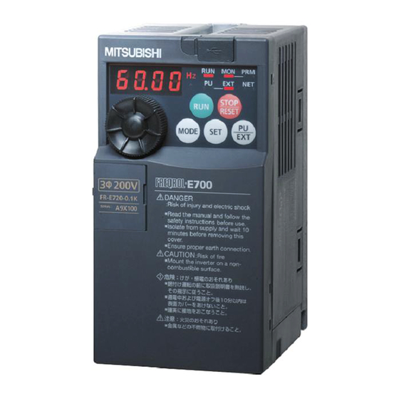
Product checking and parts identification 1 OUTLINE Product checking and parts identification Unpack the inverter and check the capacity plate on the front cover and the rating plate on the inverter side face to ensure that the product agrees with your order and the inverter is intact. ... -
Page 6: Product Checking And Parts Identification
Product checking and parts identification Accessory · Fan cover fixing screws (M3 35mm) Capacity Quantity These screws are necessary for compliance with the EU Directive FR-E720-1.5K to 3.7K, FR-E740-1.5K to 3.7K, FR-E720S-0.75K to 2.2K (Refer to page 53) FR-E720-5.5K to 15K, FR-E740-5.5K to 15K REMARKS ... - Page 7 Shows the frequency, parameter number, etc. Stop operation Used to stop Run command. Setting dial Fault can be reset when protective (Setting dial: Mitsubishi Electric inverter function is activated (fault). dial) Used to change the frequency setting and Operation mode switchover parameter settings.
- Page 8 Operation panel 1.2.2 Basic operation (factory setting) Operation mode switchover At power-ON (External operation mode) PU Jog operation mode (Example) PU operation mode Value change and frequency blink. (output frequency monitor) Frequency setting has been written and completed!! STOP Output current monitor Output voltage monitor Display the Parameter setting mode...
-
Page 9: Changing The Parameter Setting Value
Operation panel 1.2.3 Changing the parameter setting value Operation example Change the Pr. 1 Maximum frequency setting. Operation Screen at power-ON The monitor display appears. REMARKS Operation mode change Press to choose the PU operation mode. PU indicator is lit. is displayed...Why? Parameter setting mode appears .. -
Page 10: Installation And Wiring
2 INSTALLATION AND WIRING AC power supply Use within the permissible power supply specifications of the inverter. To ensure USB connector safety, use a molded case circuit breaker, A personal computer and earth leakage circuit breaker or magnetic an inverter can be connected Enclosure surface operation panel contactor to switch power ON/OFF. - Page 11 Earth Leakage Circuit Breaker Output (ELB) (NF, NV type) Model (kW) Reactor connection Reactor connection FR-HAL FR-HEL without with without with FR-E720-0.1K S-T10 S-T10 0.4K 0.4K FR-E720-0.2K S-T10 S-T10 0.4K 0.4K FR-E720-0.4K S-T10 S-T10 0.4K 0.4K...
- Page 12 Before installation, remove the front cover and the wiring cover. (Remove the covers in the directions of the arrows.) For the FR-E720-3.7K or lower, FR-E740-7.5K or lower, or FR-E720S-2.2K or lower inverter, additionally remove the Ethernet board. (Refer to page 17.) FR-E720-0.1K to 0.75K FR-E720-1.5K to 3.7K FR-E720-5.5K to 15K FR-E720S-0.1K to 0.4K...
-
Page 13: Terminal Connection Diagram
Wiring Wiring 2.3.1 Terminal connection diagram *1. DC reactor (FR-HEL) Sink logic When connecting a DC reactor, remove the Main circuit terminal jumper across P1-P/+. Control circuit terminal *6 A brake transistor is not built-in to the Single-phase power input Brake unit 0.1K and 0.2K. -
Page 14: Terminal Specifications
Wiring 2.3.2 Terminal specifications Terminal Type Terminal Name Description Symbol R/L1, S/L2, Connect to the commercial power supply. Keep these terminals open when using the high AC power input T/L3 * power factor converter (FR-HC) or power regeneration common converter (FR-CV). U, V, W Inverter output Connect a three-phase squirrel-cage motor. - Page 15 N/-. Opposite polarity will damage the inverter. 2.3.3 Terminal arrangement of the main circuit terminal, power supply and the motor wiring Three-phase 200V/400V class FR-E720-0.1K to 0.75K FR-E720-1.5K to 3.7K FR-E740-0.4K to 3.7K Jumper N/- P/+...
- Page 16 Wiring FR-E720-5.5K, 7.5K FR-E740-5.5K, 7.5K R/L1 S/L2 T/L3 R/L1 S/L2 T/L3 Jumper P/+ PR P/+ PR Jumper Power supply Motor Power supply Motor FR-E720-11K, 15K FR-E740-11K, 15K P/+ PR R/L1 S/L2 T/L3 R/L1 S/L2 T/L3 Jumper Jumper Power supply Motor Power supply Motor Single-phase 200V class...
- Page 17 S/L2 U, V, W S/L2 U, V, W S/L2 U, V, W S/L2 U, V, W cable cable T/L3 T/L3 T/L3 T/L3 FR-E720-0.1K to 0.75K M3.5 2-3.5 2-3.5 FR-E720-1.5K, 2.2K FR-E720-3.7K 5.5-4 5.5-4 FR-E720-5.5K 5.5-5 5.5-5 FR-E720-7.5K 14-5 FR-E720-11K 14-5...
- Page 18 Wiring (2) Total wiring length The overall wiring length for connection of a single motor or multiple motors should be within the value in the table below. Cable Pr. 72 Setting Voltage 3.7K 0.1K 0.2K 0.4K 0.75K 1.5K 2.2K Type (carrier frequency) Class or Higher...
-
Page 19: Wiring Of Control Circuit
Wiring 2.3.4 Wiring of control circuit Terminal layout Terminal screw size M3: (Terminal A, B, C) M2: (Other than the above) 4 RUN FU SE STF STR Wiring method 1) Strip off the sheath of the wire of the control circuit to wire. Strip off the sheath about the length below. - Page 20 Wiring (1) Control circuit common terminals (SD, 5, SE) Terminals SD, SE and 5 are common terminals for I/O signals. (All common terminals are isolated from each other.) Do not earth them. Avoid connecting the terminals SD and 5 and the terminals SE and 5. ...
- Page 21 Removal of the Ethernet board Removal of the Ethernet board The Ethernet board is installed in the initial status. Before wiring cables to the control circuit terminals or to the main circuit terminals on the FR-E720-3.7K or lower, FR-E740-7.5K or lower, or FR-E720S-0.75K or lower inverter, remove the Ethernet board as follows.
-
Page 22: Connection To The Pu Connector
Earthing (grounding) for Ethernet board Earthing (grounding) for Ethernet board To reduce noise of the Ethernet cable, connect an earth (ground) cable from the lower left M3 mounting screw on the Ethernet board to the inverter enclosure (the earth cable must be as short as possible). For earth (ground) connection to the enclosure Connection to the PU connector The PU connector can be used to connect the parameter unit (FR-PU07), enclosure surface operation panel (FR-PA07),... - Page 23 (Always install a thermal relay when using a brake resistor whose capacity is 11K or higher) When the power supply is 400V class, install a step-down transformer. Thermal Relay Type Power Supply Brake Resistor (Mitsubishi Electric Rated operating current Voltage product) MRS120W200 TH-T25-0.7A...
-
Page 24: Precautions For Use Of The Inverter
Provide a common mode choke on the output side of the inverter. (This is effective regardless of the use of the capacitive filter.) Mitsubishi Electric capacitive filter: FR-BIF, SF[], FR-E5NF-[], FR-S5NFSA[], FR-BFP2-[] ® Recommended common mode choke: FT-3KM F series FINEMET common mode choke cores manufactured by Hitachi Metals, Ltd. - Page 25 PRECAUTIONS FOR USE OF THE INVERTER (10) A short circuit or earth (ground) fault on the inverter output side may damage the inverter modules. Fully check the insulation resistance of the circuit prior to inverter operation since repeated short circuits may damage ...
- Page 26 PRECAUTIONS FOR USE OF THE INVERTER (19) Instructions for overload operation When performing operation of frequent start/stop of the inverter, rise/fall in the temperature of the transistor element of the inverter will repeat due to a repeated flow of large current, shortening the life from thermal fatigue. Since thermal fatigue is related to the amount of current, the life can be increased by reducing current at locked condition, starting current, etc.
-
Page 27: Failsafe Of The System Which Uses The Inverter
When a fault occurs, the inverter trips to output a fault signal. However, a fault output signal may not be output at an inverter fault occurrence when the detection circuit or output circuit fails, etc. Although Mitsubishi Electric assures best quality... -
Page 28: Driving The Motor
Start/stop from the operation panel (PU operation) 5 DRIVING THE MOTOR The inverter needs frequency command and start command. Frequency command Frequency command (set frequency) determines the rotation speed of the motor. Turning ON the start command starts the motor to rotate. Frequency Output REMARKS... - Page 29 Start/stop from the operation panel (PU operation) 5.1.2 Using the setting dial like a potentiometer to perform operation POINT Set "0" (extended parameter valid) in Pr. 160 User group read selection. Set "1" (setting dial potentiometer mode) in Pr. 161 Frequency setting/key lock operation selection. Operation example Change the frequency from 0Hz to 60Hz during operation Operation...
- Page 30 Start/stop from the operation panel (PU operation) 5.1.3 Setting the frequency by switches (three-speed setting) (Pr. 4 to Pr. 6) POINT Use the operation panel ( to give a start command. Switch ON the RH, RM, or RL signal to give a frequency command. ...
- Page 31 Start/stop from the operation panel (PU operation) 5.1.4 Setting the frequency by analog input (voltage input/current input) POINT Use the operation panel ( to give a start command. Use the potentiometer (frequency setting potentiometer) (voltage input) or 4-to-20mA input (current input) to give a frequency command.
- Page 32 Start and stop using terminals (External operation) Start and stop using terminals (External operation) POINT From where is the frequency command given? Operation at the frequency set in the frequency setting mode of the operation panel refer to 5.2.1 (Refer to page 28) ...
- Page 33 Start and stop using terminals (External operation) 5.2.2 Setting the frequency by switches (three-speed setting) (Pr. 4 to Pr. 6) POINT Switch ON the STF (STR) signal to give a start command. Switch ON the RH, RM, or RL signal to give a frequency command. [Connection diagram] Inverter Speed 1...
- Page 34 Start and stop using terminals (External operation) 5.2.3 Setting the frequency by analog input (voltage input/current input) POINT Switch ON the STF(STR) signal to give a start command. Use the potentiometer (frequency setting potentiometer) (voltage input) or 4-to-20mA input (current input) to give a frequency command.
- Page 35 Start and stop using terminals (External operation) 5.2.4 Operating at 60Hz or higher using the external potentiometer < How to change the maximum frequency> Changing When you want to use 0 to 5VDC input frequency setting potentiometer to change the frequency at 5V from 60Hz (initial value) example to 70Hz, make adjustment to output "70Hz"...
- Page 36 The motor capacity should be equal to or one rank lower than the inverter capacity. (Note that the capacity should be 0.1kW or higher.) Motor to be used is any of Mitsubishi Electric standard motor (SF-JR 0.2kW or more), high efficiency motor (SF- HR 0.2kW or more) or Mitsubishi Electric constant-torque motor (SF-JRCA four-pole, SF-HRCA 0.2kW to 15kW).
-
Page 37: Test Run
Set the motor. (Pr. 71) Pr. 71 Setting Motor Remarks Mitsubishi Electric SF-JR 0 (initial value) standard motor SF-HR Mitsubishi Electric high Others Offline auto tuning is necessary. efficiency motor SF-JRCA 4P Mitsubishi Electric SF-HRCA constant-torque motor ... - Page 38 (Refer to page 9) Set the motor.(Pr. 71) Pr. 71 Setting Motor Remarks Mitsubishi Electric SF-JR 0 (initial value) standard motor SF-HR Mitsubishi Electric high Others Offline auto tuning is necessary. efficiency motor SF-JRCA 4P Mitsubishi Electric SF-HRCA constant-torque motor ...
-
Page 39: Energy Saving Operation For Fans And Pumps
ENERGY SAVING OPERATION FOR FANS AND PUMPS 6 ENERGY SAVING OPERATION FOR FANS AND PUMPS Set the following functions to perform energy saving operation for fans and pumps. (1) Load pattern selection (Pr. 14) Select the optimum output characteristic (V/F characteristic) that is suitable for the Pr. -
Page 40: Parameters
Parameter list 7 PARAMETERS Simple variable-speed operation can be performed with the inverter in the initial settings. Set the required parameters according to the load and operating conditions. Use the operation panel to set or change a parameter. Parameter list REMARKS ... - Page 41 Parameter list Setting Initial Setting Initial Parameter Name Parameter Name Range Value Range Value 1 to 3, 5, 0 to 1000mH 7 to 12, 14, Motor constant (L2)/q-shaft (0 to 50, FM terminal function selection 9999 21, 24, 52, inductance 0 to ****), 53, 61, 62 9999...
- Page 42 Parameter list Setting Initial Setting Initial Parameter Name Parameter Name Range Value Range Value 0 to 400Hz, Multi-speed setting (speed 12) 9999 Parameter for manufacturer setting. Do not set. 9999 0 to 400Hz, Watt-hour meter clear 0, 10, 9999 9999 Multi-speed setting (speed 13) 9999 9999...
- Page 43 Parameter list Setting Initial Setting Initial Parameter Name Parameter Name Range Value Range Value 0 to 6, 99, Inverter Current average value monitor Password lock level 100 to 106, 9999 0 to 500A rated signal output reference current 199, 9999 current (0 to 5), Energization time carrying-...
- Page 44 Parameter list The range differs according to the Pr. 71 setting. Setting Initial Parameter Name Set this parameter when calibrating the operation panel built-in Range Value potentiometer for the FR-E500 series operation panel (PA02) connected Input phase loss protection ...
-
Page 45: Troubleshooting
Reset method of protective function 8 TROUBLESHOOTING When a fault occurs in the inverter, the inverter output is shut off and the PU display automatically changes to one of the following fault or alarm indications. If the fault does not correspond to any of the following faults or if you have any other problem, please contact your sales representative. - Page 46 List of fault displays List of fault displays When a fault occurs in the inverter, the inverter trips and the PU display automatically changes to one of the following fault or alarm indications. The error message shows an operational error. The inverter output is not shut off. Warnings are messages given before faults occur.
- Page 47 List of fault displays Function Name Description Corrective action Display Set the acceleration time longer. (Shorten the downward acceleration time in vertical lift application.) If "E.OC1" always appears at start, disconnect the motor once and restart the inverter. If "E.OC1" still appears, the inverter may be faulty.
- Page 48 OFF returns the inverter to the status before RAM write. Please contact your sales representative. The control circuit board and the main circuit Internal board fault (For parts replacement, consult the nearest Mitsubishi Electric board do not match. FA Center.) A communication error has occurred between the PU and the inverter.
- Page 49 Check first when you have a trouble Function Name Description Corrective action Display Take measures against noises if there are devices producing excess electrical noises around the inverter. An error has occurred in the CPU and in the Check the connection between the terminals PC and SD. (E6/ CPU fault peripheral circuits.
-
Page 50: Precautions For Maintenance And Inspection
Inspection items 9 PRECAUTIONS FOR MAINTENANCE AND INSPECTION The inverter is a static unit mainly consisting of semiconductor devices. Daily inspection must be performed to prevent any fault from occurring due to the adverse effects of the operating environment, such as temperature, humidity, dust, dirt and vibration, changes in the parts with time, service life, and other factors. -
Page 51: Inspection Item
Estimated lifespan for when the yearly average surrounding air temperature is 40°C (without corrosive gas, flammable gas, oil mist, dust and dirt etc.) Output current: 80% of the inverter rated current NOTE For parts replacement, consult the nearest Mitsubishi Electric FA Center. -
Page 52: Specifications
Rating 10 SPECIFICATIONS 10.1 Rating Three-phase 200V power supply Model FR-E720-K-NE 0.75 Applicable motor capacity (kW) 0.75 Rated capacity (kVA) 13.1 18.7 23.9 17.5 Rated current (A) (0.8) (1.4) (2.5) (4.1) (10) (16.5) (23) (31) (44) (57) Overload current rating ... - Page 53 Common specifications The applicable motor capacity indicated is the maximum capacity applicable for use of the Mitsubishi Electric 4-pole standard motor. The rated output capacity assumes the following output voltages: 230V for three-phase 200V/single-phase 200V, and 440V for three-phase 400V.
- Page 54 Outline dimension drawings 10.3 Outline dimension drawings FR-E720-0.1K to 0.75K-NE FR-E720S-0.1K to 0.4K-NE φ5 hole Capacity plate Inverter Model FR-E720-0.1K, 0.2K-NE FR-E720S-0.1K, 0.2K-NE FR-E720-0.4K-NE FR-E720-0.75K-NE FR-E720S-0.4K-NE (Unit: mm) FR-E720-1.5K, 2.2K-NE FR-E720S-0.75K, 1.5K-NE 2-φ5 hole Rating plate Capacity plate Inverter Model FR-E720-1.5K, 2.2K-NE...
- Page 55 Outline dimension drawings FR-E720-3.7K-NE 2-φ5 hole Rating plate Capacity plate 66.5 (Unit: mm) FR-E720-5.5K to 15K-NE FR-E740-11K, 15K-NE 2-φ6 hole Rating plate Capacity plate Inverter Model FR-E720-5.5K, 7.5K-NE 192.5 71.5 FR-E720-11K, 15K-NE 217.5 84.5 10.5 FR-E740-11K, 15K-NE (Unit: mm)
- Page 56 Outline dimension drawings FR-E740-0.4K to 3.7K-NE FR-E720S-2.2K-NE 2-φ5 hole Rating plate Capacity plate Inverter Model FR-E740-0.4K, 0.75K-NE 141.5 FR-E740-1.5K, 2.2K, 3.7K-NE 162.5 FR-E720S-2.2K-NE (Unit: mm) FR-E740-5.5K, 7.5K-NE 2-φ5 hole Rating plate Capacity plate 174.5 (Unit: mm)
- Page 57 CE marking. The authorized representative in the EU The authorized representative in the EU is shown below. Name: Mitsubishi Electric Europe B.V. Address: Mitsubishi-Electric-Platz 1, 40882 Ratingen, Germany Note We declare that this inverter, when equipped with the dedicated EMC filter, conforms with the EMC Directive in industrial environments and affix the CE marking on the inverter.
- Page 58 (2) Low Voltage Directive We have self-confirmed our inverters as products compliant to the Low Voltage Directive (Conforming standard EN 61800- 5-1) and affix the CE marking on the inverters. Outline of instructions Do not use an earth leakage circuit breaker as an electric shock protector without connecting the equipment to the earth. Connect the equipment to the earth securely.
- Page 59 Pr. 9 = 100% setting of inverter rating∗2 Pr. 9 = 50% setting of inverter rating∗1, 2 output. (The operation characteristic is shown on the left.) 30Hz or more ∗3 • When using the Mitsubishi Electric 30Hz or more ∗3 20Hz constant-torque motor...
-
Page 60: Appendix 2 Instructions For Ul And Cul
Model Manufacturer Rated Voltage, Vac MMP-T32 Mitsubishi Electric Corp. 480Y/277 Suitable for Use in a Circuit Capable of Delivering Not More Than 50 or 25 kA rms Symmetrical Amperes, 480Y/277 Volts Maximum when protected by the Type E Combination motor Controllers indicated in the above table. -
Page 61: Appendix 3 Serial Number Check
The SERIAL number (refer to Appendix 3) can be checked on the rating plate (refer to page 1) of the product. • Authorized sales representative (importer) in the CU area The authorized sales representative (importer) in the CU area is shown below. Name: Mitsubishi Electric (Russia) LLC Address: 52, bld 1 Kosmodamianskaya Nab 115054, Moscow, Russia Phone: +7 (495) 721-2070... - Page 62 Appendix 5 Restricted Use of Hazardous Substances in Electronic and Electrical Products The mark of restricted use of hazardous substances in electronic and electrical products is applied to the product as follows based on the “Management Methods for the Restriction of the Use of Hazardous Substances in Electrical and Electronic Products” of the People's Republic of China.
- Page 63 (1) Damages caused by any cause found not to be the responsibility of Mitsubishi Electric. (2) Loss in opportunity, lost profits incurred to the user by Failures of Mitsubishi Electric products. (3) Special damages and secondary damages whether foreseeable or not, compensation for accidents, and compensation for damages to products other than Mitsubishi Electric products.
- Page 64 REVISIONS *The manual number is given on the bottom left of the back cover. Print Date Revision Manual Number May 2017 IB(NA)-0600712ENG-A First edition Jun. 2017 IB(NA)-0600712ENG-B Addition MODBUS/TCP iQSS MELSOFT/FA product connection...
- Page 65 MITSUBISHI ELECTRIC EUROPE B.V. MITSUBISHI ELECTRIC AUTOMATION India Pune FA Center Polish Branch (CHINA) LTD. Guangzhou Office MITSUBISHI ELECTRIC INDIA PVT. LTD. ul. Krakowska 50, 32-083 Balice, Poland Room 1609, North Tower, The Hub Center, Pune Branch TEL. 48-12-630-47-00 No.1068, Xingang East Road, Haizhu Emerald House, EL -3, J Block, M.I.D.C...
- Page 66 HEAD OFFICE: TOKYO BUILDING 2-7-3, MARUNOUCHI, CHIYODA-KU, TOKYO 100-8310, JAPAN IB(NA)-0600712ENG-B(1706)MEE Printed in Japan Specifications subject to change without notice.