Table of Contents
Advertisement
Quick Links
TYPICAL WIRING DIAGRAM
A larger version of the diagram is available in the products operators manual. DSE Part No: 057-173
DIMENSIONS AND MOUNTING
For flat surface mounting in a Type 1 enclosure
DIMENSIONS
245 mm x 184 mm x 50 mm (9.6" x 7.2" x 2.0")
to meet UL requirements
PANEL CUTOUT
220mm x 160mm (8.7" x 6.3")
D E E P S E A E L E C T R O N I C S
D S E 8 8 6 0 I N S T A L L A T I O N I N S T R U C T I O N S
ACCESSING THE MAIN FRONT PANEL CONFIGURATION EDITOR
Ensure the generator(s) is at rest and the module is in STOP mode by pressing the Stop/Reset
•
button.
•
Press and hold the
Stop button and
•
If a module security PIN has been set, the PIN number request is then shown.
Press
, the first '#' changes to '0'. Press
•
value.
Press
(right) button when the first digit is correctly entered. The digit you have just entered will
•
now show '#' for security.
•
The other digits of the PIN number. You can press
adjust one of the previous digits.
•
When
is pressed after editing the final PIN digit, the PIN is checked for validity. If the number is
not correct, you must re-enter the PIN.
If the PIN has been successfully entered (or the module PIN has not been enabled), the editor is
•
displayed.
EDITING A PARAMETER
Enter the editor as described above.
•
•
Press the
(up),
(down),
view/change.
Then press
(up) or
(down) to cycle to the parameter within the section you have chosen.
•
•
To edit the parameter, press
to enter edit mode. The parameter is highlighted blue to indicate
that you are editing the value.
Press the up or down buttons to change the parameter to the required value.
•
•
Press
to save the value. The parameter ceases flashing to indicate that it has been saved.
To exit the editor at any time, press and hold the
•
N N N N O O O O T T T T E E E E : : : : T T T T h h h h e e e e P P P P I I I I N N N N n n n n u u u u m m m m b b b b e e e e r r r r i i i i s s s s n n n n o o o o t t t t s s s s e e e e t t t t b b b b y y y y D D D D S S S S E E E E w w w w h h h h e e e e n n n n t t t t h h h h e e e e m m m m o o o o d d d d u u u u l l l l e e e e l l l l e e e e a a a a v v v v e e e e s s s s t t t t h h h h e e e e f f f f a a a a c c c c t t t t o o o o r r r r y y y y . . . . I I I I f f f f t t t t h h h h e e e e m m m m o o o o d d d d u u u u l l l l e e e e
has a PIN c c c c o o o o d d d d e e e e s s s s e e e e t t t t , , , , t t t t h h h h i i i i s s s s h h h h a a a a s s s s b b b b e e e e e e e e n n n n i i i i m m m m p p p p l l l l e e e e m m m m e e e e n n n n t t t t e e e e d d d d b b b b y y y y y y y y o o o o u u u u r r r r g g g g e e e e n n n n e e e e r r r r a a a a t t t t o o o o r r r r s s s s u u u u p p p p p p p p l l l l i i i i e e e e r r r r w w w w h h h h o o o o s s s s h h h h o o o o u u u u l l l l d d d d b b b b e e e e
has a PIN
has a PIN
has a PIN
c c c c o o o o n n n n t t t t a a a a c c c c t t t t e e e e d d d d i i i i f f f f y y y y o o o o u u u u r r r r e e e e q q q q u u u u i i i i r r r r e e e e t t t t h h h h e e e e c c c c o o o o d d d d e e e e . . . . I I I I f f f f t t t t h h h h e e e e c c c c o o o o d d d d e e e e h h h h a a a a s s s s b b b b e e e e e e e e n n n n ' ' ' ' l l l l o o o o s s s s t t t t ' ' ' ' o o o o r r r r ' ' ' ' f f f f o o o o r r r r g g g g o o o o t t t t t t t t e e e e n n n n ' ' ' ' , , , , t t t t h h h h e e e e m m m m o o o o d d d d u u u u l l l l e e e e m m m m u u u u s s s s t t t t b b b b e e e e
returned to the DSE factory to have the module's code removed. A charge will be
returned to the DSE factory to have the module's code removed. A charge will be m m m m a a a a d d d d e e e e f f f f o o o o r r r r t t t t h h h h i i i i s s s s
returned to the DSE factory to have the module's code removed. A charge will be
returned to the DSE factory to have the module's code removed. A charge will be
procedure. T T T T h h h h e e e e P P P P I I I I N N N N n n n n u u u u m m m m b b b b e e e e r r r r i i i i s s s s a a a a u u u u t t t t o o o o m m m m a a a a t t t t i i i i c c c c a a a a l l l l l l l l y y y y r r r r e e e e s s s s e e e e t t t t w w w w h h h h e e e e n n n n t t t t h h h h e e e e e e e e d d d d i i i i t t t t o o o o r r r r i i i i s s s s e e e e x x x x i i i i t t t t e e e e d d d d ( ( ( ( m m m m a a a a n n n n u u u u a a a a l l l l l l l l y y y y o o o o r r r r
procedure.
procedure.
procedure.
automatically) to ensure security.
automatically) to ensure security.
automatically) to ensure security.
automatically) to ensure security.
NOTE: The editor automatically exits after 5 minutes of inactivity to ensure security.
NOTE: The editor automatically exits after 5 minutes of inactivity to ensure security.
NOTE: The editor automatically exits after 5 minutes of inactivity to ensure security.
NOTE: The editor automatically exits after 5 minutes of inactivity to ensure security.
Tick button together.
(up) or
(down) button to adjust it to the correct
(left) button if you need to move back to
(left) and
(right) to cycle to the section you wish to
or
button.
053-139
ISSUE 1
Advertisement
Table of Contents

Related Manuals for DSE 8860


Summary of Contents for DSE 8860
- Page 1 DSE factory to have the module’s code removed.
- Page 2 • Automatic hours run balancing and alarms can be made using the • Mains (Utility) de-coupling SHOCK DSE PC Configuration Suite The module can indicate operational • Mains (Utility) de-coupling BS EN 60068-2-27 Software. Selected configuration is status and fault conditions on the...
- Page 3 Modules can be integrated into • Multiple mains (utility) monitoring, • Backed up real time clock building management systems when using multiple DSE8860s • Fully configurable via DSE (BMS) • Peak lopping Configuration Suite PC software • Licence-free PC software •...
-
Page 4: Dse8860 Operators Manual Issue
DEEP SEA ELECTRONICS PLC DSE8860 Controller Operators Manual Document Number: 057-173 Author: Ashley Senior DSE8860 Operators Manual ISSUE 1... - Page 5 Deep Sea Electronics Plc at the address above. The DSE logo is a UK registered trademarks of Deep Sea Electronics PLC. Any reference to trademarked product names used within this publication is owned by their respective companies.
-
Page 6: Table Of Contents
DSE8860 Operators Manual TABLE OF CONTENTS Section Page BIBLIOGRAPHY ....................7 INSTALLATION INSTRUCTIONS ..................7 TRAINING GUIDES ......................7 MANUALS ........................... 8 THIRD PARTY DOCUMENTS ..................... 8 INTRODUCTION ....................9 SPECIFICATIONS ..................10 PART NUMBERING ......................10 3.1.1 SHORT NAMES ......................10 TERMINAL SPECIFICATION .................... - Page 7 DSE8860 Operators Manual 3.13 APPLICABLE STANDARDS ..................31 3.13.1 BS, UL AND IEEE CLASSIFICATIONS ..............31 3.13.2 ENCLOSURE CLASSIFICATIONS ................33 3.13.3 NEMA CLASSIFICATIONS ..................34 INSTALLATION ..................... 35 USER CONNECTIONS ...................... 35 TERMINAL DESCRIPTION ....................36 4.2.1 DC SUPPLY, FUEL AND START OUTPUTS, OUTPUTS E-J ........36 4.2.2 ANALOGUE SENSOR ....................
- Page 8 12.2 LOADING ........................94 12.3 COMMUNICATIONS ...................... 95 12.4 INSTRUMENTS ......................96 12.5 MISCELLANEOUS ......................96 DSE 4 STEPS TO SUCCESSFUL SYNCHRONISING ....... 97 13.1 CONTROL ........................97 13.2 METERING........................97 13.3 COMMUNICATIONS ...................... 97 13.4 SYNC CHECKS ......................97...
- Page 9 DSE8860 Operators Manual MAINTENANCE, SPARES, REPAIR AND SERVICING ......98 14.1 PURCHASING ADDITIONAL CONNECTOR PLUGS FROM DSE ....... 98 14.1.1 PACK OF PLUGS ....................... 98 14.1.2 INDIVIDUAL PLUGS ....................98 14.2 PURCHASING ADDITIONAL FIXING CLIPS FROM DSE ..........98 14.3 PURCHASING ADDITIONAL SEALING GASKET FROM DSE ........
-
Page 10: Bibliography
Bibliography 1 BIBLIOGRAPHY This document refers to and is referred to by the following DSE publications which can be obtained from the DSE website: www.deepseaplc.com 1.1 INSTALLATION INSTRUCTIONS Installation instructions are supplied with the product in the box and are intended as a ‘quick start’... -
Page 11: Manuals
Bibliography 1.3 MANUALS Product manuals are can be downloaded from the DSE website: www.deepseaplc.com DSE PART DESCRIPTION 057-045 Guide to Synchronising and Load Sharing Part 1 057-046 Guide to Synchronising and Load Sharing Part 2 057-047 Load Share Design and Commissioning Guide... -
Page 12: Introduction
• R.O.C.O.F. and Vector shift for detection of mains failure when in parallel with the mains supply. • Integral PLC to help provide customisation where required Using a PC and the DSE Configuration Suite software allows alteration of selected operational sequences, timers, alarms and operational sequences. Additionally, the module’s integral fascia configuration editor allows adjustment of a subset of this information. -
Page 13: Specifications
NOTE: NOTE: NOTE: NOTE: For purchasing additional connector plugs from DSE, please see the section For purchasing additional connector plugs from DSE, please see the section For purchasing additional connector plugs from DSE, please see the section For purchasing additional connector plugs from DSE, please see the section entitled Maintenance, Spares, Repair and Servicing elsewhere in this document. -
Page 14: Power Supply Requirements
Specification 3.3 POWER SUPPLY REQUIREMENTS Minimum Supply Voltage 8 V continuous Able to survive 0 V for 50 mS providing the supply was at least Cranking Dropouts 10 V before the dropout and recovers to 5 V afterwards. Maximum Supply Voltage 35 V continuous (60 V protection) Reverse Polarity Protection -35 V continuous... -
Page 15: Current Sensing
NOTE: CTs with 5 CTs with 5 CTs with 5 CTs with 5 A secondary windings are recommended with DSE modules. 1 A secondary windings are recommended with DSE modules. 1 A secondary windings are recommended with DSE modules. 1 A secondary windings are recommended with DSE modules. -
Page 16: Ct Polarity
3.5.3 CT PHASING Take particular care that the CTs are connected to the correct phases. For instance, ensure that the CT on phase 1 is connected to the terminal on the DSE module intended for connection to the CT for phase 1. -
Page 17: Inputs
3.6 INPUTS 3.6.1 ANALOGUE INPUTS C & D NOTE: NOTE: Refer to DSE8860 PC Software Configuration Manual (DSE part 057 Refer to DSE8860 PC Software Configuration Manual (DSE part 057- - - - 174) 174) for NOTE: NOTE: Refer to DSE8860 PC Software Configuration Manual (DSE part 057... -
Page 18: Digital Inputs A, B, C, D, E, F, G, H, I, J, K & L
NOTE: Refer to DSE8860 PC Software Configuration Manual (DSE part 057 Refer to DSE8860 PC Software Configuration Manual (DSE part 057 Refer to DSE8860 PC Software Configuration Manual (DSE part 057- - - - 174) Refer to DSE8860 PC Software Configuration Manual (DSE part 057... -
Page 19: Communication Ports
NOTE: Refer to DSE8860 PC Software Configuration Manual (DSE part 057 Refer to DSE8860 PC Software Configuration Manual (DSE part 057 Refer to DSE8860 PC Software Configuration Manual (DSE part 057- - - - 174) Refer to DSE8860 PC Software Configuration Manual (DSE part 057... -
Page 20: Usb Connection
The USB port is provided to give a simple means of connection between a PC and the controller. Using the DSE Configuration Suite Software, the operator is then able to control the module, starting or stopping the generator, selecting operating modes, etc. -
Page 21: Rs232
GSM modem for more remote communications. Many PCs are not fitted with an internal RS232 serial port. DSE DO NOT recommend the use of USB to RS232 convertors but can recommend PC add-ons to provide the computer with an RS232 port. -
Page 22: Recommended External Modems
• messages to designated mobile phones upon status and alarm conditions. For a data connection to a PC running DSE Configuration Suite Software, a ‘special’ CSD • (Circuit Switched Data) SIM card is required that will enable the modem to answer an incoming data call. -
Page 23: Rs485
3.8.4 RS485 The RS485 ports on the controller support the Modbus RTU protocol. The DSE Gencomm register table for the controller is available upon request from the DSE Technical Support Department. RS485 is used for point-to-point cable connection of more than one device (maximum 32 devices) and allows for connection to PCs, PLCs and Building Management Systems (to name just a few devices). -
Page 24: Ethernet
3.8.5 ETHERNET The Ethernet port on the controller supports the Modbus TCP protocol. The DSE Gencomm register table for the controller is available upon request from the DSE Technical Support Department. Ethernet is allows for connection to PCs, PLCs and Building Management Systems and LAN (Local Area Networks) to name just a few devices. -
Page 25: Direct Pc Connection
Specification 3.8.5.1 DIRECT PC CONNECTION Requirements DSE module with the ability to connect to Ethernet • Crossover Ethernet cable (see Below) • PC with Ethernet port • Crossover network cable Crossover cable wiring detail For the advanced Engineer, a crossover... -
Page 26: Connection To Basic Ethernet
Specification 3.8.5.2 CONNECTION TO BASIC ETHERNET Requirements DSE module with the ability to connect to Ethernet • Ethernet cable (see below) • Working Ethernet (company or home network) • PC with Ethernet port • Ethernet cable Ethernet router or ADSL router... -
Page 27: Connection To Company Infrastructure Ethernet
NOTE: DSE Stock a 2m (2yds) Ethernet Cable DSE Stock a 2m (2yds) Ethernet Cable DSE Stock a 2m (2yds) Ethernet Cable DSE Stock a 2m (2yds) Ethernet Cable – – – – Part number 016 Part number 016 Part number 016 Part number 016- - - - 137. -
Page 28: Connection To The Internet
NOTE: DSE Stock a 2m (2yds) Ethernet Cable DSE Stock a 2m (2yds) Ethernet Cable DSE Stock a 2m (2yds) Ethernet Cable DSE Stock a 2m (2yds) Ethernet Cable – – – – Part number 016 Part number 016 Part number 016 Part number 016- - - - 137. -
Page 29: Firewall Configuration For Internet Access
FIREWALL CONFIGURATION FOR INTERNET ACCESS As modem/routers differ enormously in their configuration, it is not possible for DSE to give a complete guide to their use with the module. However it is possible to give a description of the requirements in generic terms. -
Page 30: Dsenet® For Expansion Modules
Specification 3.9 DSENET® FOR EXPANSION MODULES DSENet® is the interconnection cable between the host controller and the expansion module(s) and must not be connect to any device other than DSE equipment designed for connection to the DSENet® Cable Type Two core screened twisted pair Cable Characteristic 120Ω... -
Page 31: Sounder
64db @ 1m 3.10.1 ADDING AN EXTERNAL SOUNDER TO THE APPLICATION Should an external alarm or indicator be required, this can be achieved by using the DSE Configuration Suite PC software to configure an auxiliary output for “Audible Alarm”, and by configuring an auxiliary input for “Alarm Mute”... -
Page 32: Dimensions And Mounting
Specification 3.12 DIMENSIONS AND MOUNTING 3.12.1 DIMENSIONS 245 mm x 184 mm x 50 mm (9.6” x 7.2” x 2.0”) 3.12.2 PANEL CUTOUT 220mm x 160mm (8.7” x 6.3”) 3.12.3 WEIGHT 0.7kg (1.4lb) 3.12.4 FIXING CLIPS The module is held into the panel fascia using the supplied fixing clips. Withdraw the fixing clip screw (turn anticlockwise) until only the pointed end is protruding from •... -
Page 33: Cable Tie Fixing Points
Specification 3.12.5 CABLE TIE FIXING POINTS Integral cable tie fixing points are included on the rear of the module’s case to aid wiring. This additionally provides strain relief to the cable loom by removing the weight of the loom from the screw connectors, thus reducing the chance of future connection failures. -
Page 34: Applicable Standards
Specification 3.13 APPLICABLE STANDARDS 3.13.1 BS, UL AND IEEE CLASSIFICATIONS This document conforms to BS4884-1 1992 Specification for presentation BS 4884-1 of essential information. BS 4884-2 This document conforms to BS4884-2 1993 Guide to content BS 4884-3 This document conforms to BS4884-3 1993 Guide to presentation BS EN 60068-2-1 -30°C (-22°F) (Minimum temperature) - Page 35 Specification Continued… 46 – Reverse-Phase Or Phase-Balance Current Relay 48 – Incomplete Sequence Relay 49 – Machine Or Transformer Thermal Relay 50 – Instantaneous overcurrent relay 51 – AC time overcurrent relay 52 – AC circuit breaker 53 – Exciter or DC generator relay IEEE C37.2 54 –...
-
Page 36: Enclosure Classifications
Specification 3.13.2 ENCLOSURE CLASSIFICATIONS IP CLASSIFICATIONS The modules specification under BS EN 60529 Degrees of protection provided by enclosures IP65 (Front of module when module is installed into the control panel with the optional sealing gasket). IP42 (front of module when module is installed into the control panel WITHOUT being sealed to the panel) First Digit Second Digit Protection against contact and ingress of solid objects... -
Page 37: Nema Classifications
Specification 3.13.3 NEMA CLASSIFICATIONS The modules NEMA Rating (Approximate) 12 (Front of module when module is installed into the control panel with the optional sealing gasket). 2 (front of module when module is installed into the control panel WITHOUT being sealed to the panel) NOTE: NOTE: NOTE:... -
Page 38: Installation
Installation 4 INSTALLATION The module is designed to be mounted on the panel fascia. For dimension and mounting details, see the section entitled Specification, Dimension and mounting elsewhere in this document. 4.1 USER CONNECTIONS To aid user connection, icons are used on the rear of the module to help identify terminal functions. An example of this is shown below. -
Page 39: Terminal Description
Installation 4.2 TERMINAL DESCRIPTION 4.2.1 DC SUPPLY, FUEL AND START OUTPUTS, OUTPUTS E-J CABLE DESCRIPTION NOTES SIZE DC Plant Supply Input 2.5mm² (Negative) AWG 13 (Recommended Maximum Fuse 15A anti-surge) DC Plant Supply Input 2.5 mm² Supplies the module (2A anti-surge requirement) and (Positive) AWG 13 Output relays E,F,G &... -
Page 40: Magnetic Pickup, Can And Expansion
Multiset comms link. Multiset comms link. DSE stock and supply Belden cable 98 DSE stock and supply Belden cable 9841 which is a high quality 120 DSE stock and supply Belden cable 98 DSE stock and supply Belden cable 98 41 which is a high quality 120 41 which is a high quality 120Ω... -
Page 41: Load Switching And V1 Mains Voltage Sensing
Installation 4.2.4 LOAD SWITCHING AND V1 MAINS VOLTAGE SENSING CABLE DESCRIPTION NOTES SIZE 1.0mm Normally configured to control mains contactor coil Output relay C AWG 18 (Recommend 10A fuse) 1.0mm Output relay C Normally configured to control mains contactor coil AWG 18 1.0mm Normally configured to control generator contactor coil... -
Page 42: Mains Current Transformers
L is the primary of the CT that ‘points’ towards the LOAD s1 is the secondary of the CT that connects to the DSE Module’s input for the CT measuring (I1,I2,I3) s2 is the secondary of the CT that should be commoned with the s2 connections of all the other CTs and connected to the CT common terminal of the module. -
Page 43: Bus/Load Current Transformer
CT is NOT REQUIRED in a system including only one mains supply CT is NOT REQUIRED in a system including only one mains supply (with one DSE (with one DSE8 8 8 8 x x x x 6 6 6 6 0 controller). See section below detailing advantages of the 0 controller). -
Page 44: Configurable Digital Inputs
4.2.9 PC CONFIGURATION INTERFACE CONNECTOR CABLE DESCRIPTION NOTES SIZE Socket for connection to PC with This is a standard USB 0.5mm² DSE Configuration Suite type A to type B AWG 20 Software connector. NOTE: NOTE: NOTE: NOTE: The USB connection cable between the PC and the... -
Page 45: Rs232 Connector
Installation 4.2.10 RS232 CONNECTOR One configurable RS232 port is provided. Typical examples of devices that can be connected to this ports are PCs, PLCs, HMIs and Modems Terminal Description Received Line Signal Detector (Data Carrier Detect) Received Data Transmit Data Data Terminal Ready Signal Ground Data Set Ready... -
Page 46: Typical Wiring Diagram (3 Phase, 4 Wire Star)
Genset manufacturers and panel builders may use these diagrams as a starting point; however, you are referred to the completed system diagram provided by your system manufacturer for complete wiring detail. Further wiring suggestions are available in the following DSE publications, available at www.deepseaplc.com to website members. DSE PART... -
Page 47: Alternate Topologies
NOTE: Refer to DSE8860 PC Software Configuration Manual (DSE part 057 Refer to DSE8860 PC Software Configuration Manual (DSE part 057 Refer to DSE8860 PC Software Configuration Manual (DSE part 057- - - - 174) Refer to DSE8860 PC Software Configuration Manual (DSE part 057... -
Page 48: Phase (L1 & L2), 3 Wire Delta
Installation 4.3.1.2 2 PHASE (L1 & L2), 3 WIRE DELTA 4.3.1.3 2 PHASE (L1 & L3), 3 WIRE DELTA... -
Page 49: Phase, 3 Wire Delta
Installation 4.3.1.4 3 PHASE, 3 WIRE DELTA 4.3.1.5 3 PHASE, 4 WIRE DELTA... -
Page 50: Bus And Load Current Transformer Position
PC Software PC Software PC Software Configuration Manual (DSE part 057 Configuration Manual (DSE part 057 Configuration Manual (DSE part 057 Configuration Manual (DSE part 057- - - - 174) for 174) for 174) for 174) for further details on... -
Page 51: Phase, 4 Wire With A Load Current Transformer
Installation 4.3.2.2 3 PHASE, 4 WIRE WITH A LOAD CURRENT TRANSFORMER... -
Page 52: Typical System Schematics
Installation 4.3.3 TYPICAL SYSTEM SCHEMATICS 4.3.3.1 SINGLE MAINS, MULTIPLE GENERATORS... -
Page 53: Dual Mains, Multiple Generators
Installation 4.3.3.2 DUAL MAINS, MULTIPLE GENERATORS... -
Page 54: Multiple Mains, Multiple Generators
Installation 4.3.3.3 MULTIPLE MAINS, MULTIPLE GENERATORS... -
Page 55: Earth Systems
(the battery negative connects to Earth) 4.4.2 POSITIVE EARTH When using a DSE module with a Positive Earth System (the battery positive connects to Earth), the following points must be followed: Follow the typical wiring diagram as normal for all sections EXCEPT the earth points •... -
Page 56: Typical Arrangement Of Dsenet
DSE stock and supply Belden cable 9841 which is a high quality 120 DSE stock and supply Belden cable 9841 which is a high quality 120Ω Ω Ω Ω impedance cable DSE stock and supply Belden cable 9841 which is a high quality 120... -
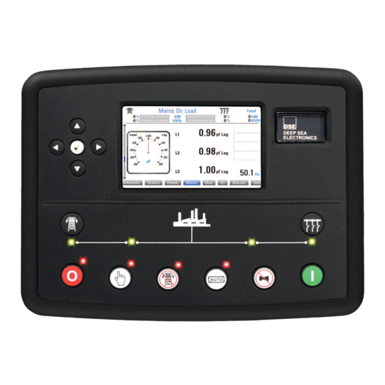
Page 57: Description Of Controls
Description Of Controls 5 DESCRIPTION OF CONTROLS 5.1 DSE8860 AUTO START CONTROL MODULE Menu Navigation Main Status and Buttons Instrumentation Display Close Bus (Manual Mode Only) Close Mains (Manual Mode Only) Start Bus Select (When in Manual) Stop Mode Select Select Test Select Auto Mute alarm /... -
Page 58: Quickstart Guide
Description Of Controls 5.2 QUICKSTART GUIDE This section provides a quick start guide to the module’s operation. 5.2.1 STARTING THE GENERATOR(S) First, Select Manual Mode… …Then Press the Start Button to start the Generator(s). NOTE: NOTE: For further details, see the section entitled ‘OPERATION’ elsewhere in th NOTE: NOTE: For further details, see the section entitled ‘OPERATION’... -
Page 59: Viewing The Instrument
Description Of Controls 5.3 VIEWING THE INSTRUMENT PAGES 5.3.1 DISPLAY OVERVIEW Side Scroll Bar The Top Section shows a configurable Summary of the Status Main Instrumentation Display The Bottom Line of the Instrument Display Indicates the Currently Selected Page 5.3.2 PAGE INDICATORS Alarms Schedule Status... -
Page 60: Side Scroll Bar
Description Of Controls 5.3.3 SIDE SCROLL BAR While a page is being viewed, the scroll bar at the side of the display represents how ‘far down’ the page you are currently viewing. Pressing the scroll buttons moves up and down the currently selected page. Examples Examples Examples... -
Page 61: Home
Description Of Controls 5.3.5 HOME In addition to the common display area, the following instruments are displayed on the home page. Pressing the scroll buttons moves up and down the pages mentioned below. Example image : Mains Mains Voltage (ph-N) •... - Page 62 Description Of Controls Bus/Mains Mode kW Bus/Mains Actual (% of Total) • kW Bus/Mains Target (% of Total) • kVAr Bus/Mains Actual (% of Total) • kVAr Bus/Mains Target (% of Total) • Ramp % • Mains Supply Information Mains Average Voltage (ph-N) •...
-
Page 63: Mains
Description Of Controls 5.3.6 MAINS Contains electrical values of the Mains (Utility), measured or derived from the module’s voltage and current inputs. Pressing the scroll buttons moves up and down the pages mentioned below. Example image: Mains Mains Voltage (ph-ph) •... - Page 64 Description Of Controls AC System Mains Configuration (AC System diagram) • Mains Configuration (Nominals) • Accumulated Mains kW h + • Mains kW h - • Mains kV A h • Mains kV Ar h • Total Mains Total Load (kW, kV A, kV Ar, Power Factor) •...
-
Page 65: Bus
Description Of Controls 5.3.7 BUS Contains electrical values of the common generator bus, this is derived from the MSC link which connects all the modules together. Pressing the scroll buttons moves up and down the pages mentioned below. Example image: Bus Voltage (ph-N) •... - Page 66 Description Of Controls Averages NOTE: Press the NOTE: Pres s the ( ( ( ( t t t t ick ick) ) ) ) button button and and the (up) and (up) and (down) buttons to cycle through the (down) buttons to cycle through the NOTE: Pres NOTE: Pres s the...
-
Page 67: I/O
Description Of Controls 5.3.8 I/O Displays the measured values of the analogue inputs C and D. Pressing the scroll buttons moves up and down the pages mentioned below. Example image:... -
Page 68: Alarms
Description Of Controls 5.3.9 ALARMS Contains all the alarms currently present on the module. Pressing the scroll buttons moves up and down the pages mentioned below. Example image: Event Log Alarm History containing up to 250 past events logged. Where more than 250 events are logged, the last •... -
Page 69: Schedule
Control V1.00.02 Graphics V1.00.03 Analogue V3.00.02 Engine V1.18 Bootloader Control V1.00 Bootloader Graphics V1.02.03 This section contains important information about the module and the firmware versions. This information may be asked for when contacting DSE Technical Support Department for advice. - Page 70 If the GSM modem is not purchased from DSE, ensure that it has been correctly set to operate at 9600 baud. The DSE Modbus Gencomm document containing register mappings inside the DSE module is available upon request from support@deepseaplc.com. Email your request along with the serial number of your DSE module to...
- Page 71 The factory settings are for the module to communicate at 19200 baud, modbus slave address 10. The DSE Modbus Gencomm document containing register mappings inside the DSE module is available upon request from support@deepseaplc.com. Email your request along with the serial number of your DSE module to ensure the correct information is sent to you.
- Page 72 Description Of Controls Pressing the scroll buttons moves up and down the pages mentioned below. Ethernet Port Up DHCP enable Disabled Host Name IP address 192.168.10.23 Modbus Port Number Subnet Mask 255.255.255.0 Gateway IP 0.0.0.0 DNS IP 0.0.0.0 MAC Address 008080EF1F2F3 Ethernet Traffic DHCP enable...
- Page 73 Description Of Controls Pressing the scroll buttons moves up and down the pages mentioned below. Logging Log State Enabled Log Destination Internal Log Mode Newest Total Log Memory 2048k Log Memory Free 1463k USB Drive State Not Detected Logging Time Remaining 26hr 52m Status Supervisor State...
-
Page 74: Facia Operation
Configuration Manual (DSE part 057 Configuration Manual (DSE part 057 Configuration Manual (DSE part 057 Configuration Manual (DSE part 057- - - - 174) for further details on configuring, 174) for further details on configuring, 174) for further details on configuring,... -
Page 75: Control Push-Buttons
Front Panel Configuration 6.2 CONTROL PUSH-BUTTONS STOP / RESET This button places the module into its Stop/Reset mode. This will clear any alarm conditions for which the triggering criteria have been removed. If the generator(s) is running and the module is put into Stop mode, the module will automatically instruct the changeover device to unload the generator bus (‘Close Bus becomes inactive (if used)) and the start request to the DSE8x10... - Page 76 Protections CLOSE MAINS This push button is used to control the closure of the mains load switching device in Manual mode and has two modes of operation : ‘Normal’ breaker button control Synchronising is NOT enabled: Pressing this button when the mains is available and off •...
-
Page 77: Operating Procedure
Front Panel Configuration 7 OPERATING PROCEDURE The following description details the sequences followed by a module containing the standard ‘factory configuration’. Remember that if you have purchased a completed generator set or control panel from your supplier, the module’s configuration will probably have been changed by them to suit their particular requirements. Always refer to your configuration source for the exact sequences and timers observed by any particular module in the field. -
Page 78: Automatic Mode
Protections 7.2 AUTOMATIC MODE panel lock panel lock panel lock panel lock NOTE NOTE: : : : If a digital input configured to NOTE NOTE If a digital input configured to If a digital input configured to If a digital input configured to is active, is active, changing module modes will not be is active,... -
Page 79: Bus Available (Generator(S) Running)
Front Panel Configuration 7.2.3 BUS AVAILABLE (GENERATOR(S) RUNNING) Once the generator bus becomes available, the load is transferred. If required, the generator bus is first synchronised with the mains supply. This operation is automatic, using the MSC data link. Load ramping takes place when appropriate, the DSE8860 controls the generator bus to provide the configured power to the load and/or mains supply. -
Page 80: Manual Mode
Protections 7.3 MANUAL MODE panel lock panel lock panel lock panel lock NOTE: NOTE: If a digital input configured to NOTE: NOTE: If a digital input configured to If a digital input configured to If a digital input configured to is active, is active, changing module mo is active,... -
Page 81: Test Mode
Front Panel Configuration 7.4 TEST MODE panel lock panel lock panel lock panel lock NOTE: NOTE: If a digital input configured to NOTE: NOTE: If a digital input configured to If a digital input configured to If a digital input configured to is active, is active, changing module modes will not be is active,... -
Page 82: Multiple Mains Operation
Protections 7.5 MULTIPLE MAINS OPERATION In a multiple mains system, the generator(s) are controlled by more than one DSE8860 mains controller and used to provide power to multiple loads. Should one or more of the mains supplies fail, the generator(s) (controlled by DSE8x10 modules) are started and supply power to the load. -
Page 83: Dse8860 Bus/Load Ct
Front Panel Configuration 7.5.2 DSE8860 BUS/LOAD CT The DSE8860 controller incorporates an optional (but recommended) extra CT for measuring the amount of power the generator bus is producing or the size of the load. Used in conjunction with the CTs measuring the amount of load on the mains supply, this CT allows the DSE8860 to determine what portion of the load is being supplied by the generator(s). -
Page 84: Protections
Protections 8 PROTECTIONS When an alarm is present, the Audible Alarm will sound and the LCD display indicates the alarm(s) that are present: Electrical Trip Mains Reverse Power 1 of 1 The audible alarm can be silenced by pressing the Mute button To reset the alarm, address the cause of the alarm, then press the Stop/Reset button 8.1 INDICATIONS Indications are non-critical and often status conditions. -
Page 85: Warnings
By default, warning alarms are self-resetting when the fault condition is removed. However enabling ‘all warnings are latched’ will cause warning alarms to latch until reset manually. This is enabled using the DSE Configuration Suite in conjunction with a compatible PC. Display... - Page 86 Protections Display Reason If the mains breaker fails to close, a warning is initiated. The LCD will Mains Failed To Close indicate ‘MAINS FAILED TO CLOSE’ and the COMMON ALARM LED will illuminate. Mains Failed To Open If the mains breaker fails to open, a warning is initiated. The LCD will indicate ‘MAINS FAILED TO OPEN’...
-
Page 87: Electrical Trips
Front Panel Configuration 8.3 ELECTRICAL TRIPS Electrical trips are latching and stop the Generator(s) but in a controlled manner. On initiation of the electrical trip condition the module will de-energise the ‘Close Bus’ Output to remove the load from the generator(s). Once this has occurred the generator controllers will start the ‘Return Delay’ timer and once the generator(s) breaker has opened, the ‘Cooldown Timer’... - Page 88 If the link breaks, the LCD will indicate ‘MSC FAILURE’ and the MSC Failure COMMON ALARM LED will illuminate. If the module detects that there is one or more DSE controller connected MSC Old Version Unit On to the MSC link that are not compatible with the module (for example earlier versions), ‘MSC OLD VERSION UNIT ON THE BUS’...
-
Page 89: Rocof / Vector Shift
Front Panel Configuration 8.4 ROCOF / VECTOR SHIFT When the mains (utility) and the generator(s) supplies are in parallel, the module monitors for a ROCOF and Vector shift trip which are set in the module’s configuration settings. NOTE: NOTE: NOTE: NOTE: This protection operates only This protection operates only This protection operates only... -
Page 90: Scheduler
7-day or 28-day cycle. Scheduled runs may be on load or off load depending upon module configuration. Example Screen capture from DSE Configuration Suite Software showing the configuration of the Exercise Scheduler. In this example the set will start at 09:00 on Monday and run for 5 hours, then start at 13:30 on Tuesday and run for 30 minutes. -
Page 91: Front Panel Configuration
NOTE: Refer to DSE8860 PC Software Configuration Manual (DSE part 057 Refer to DSE8860 PC Software Configuration Manual (DSE part 057 Refer to DSE8860 PC Software Configuration Manual (DSE part 057- - - - 174) Refer to DSE8860 PC Software Configuration Manual (DSE part 057... -
Page 92: Accessing The Main Front Panel Configuration Editor
• NOTE: The PIN number is not set by DSE when the module leaves the factory. If the NOTE: The PIN number is not set by DSE when the module leaves the factory. If the NOTE: The PIN number is not set by DSE when the module leaves the factory. If the NOTE: The PIN number is not set by DSE when the module leaves the factory. -
Page 93: Adjustable Parameters
Front Panel Configuration 10.1.2 ADJUSTABLE PARAMETERS Section Parameter Detail of Parameter Parameter Action Values Remote Start Off Load Remote Start On Load Start Timers Start Delay Telemetry Start Timers Mains Transient Delay Load Timers Tran Time/Load Delay Load/Stopping Timers Stopping Timers Return Delay Display Display... -
Page 94: Accessing The 'Maintenance' Configuration Editor
Front Panel Configuration 10.2 ACCESSING THE ‘MAINTENANCE’ CONFIGURATION EDITOR The ‘Maintenance’ Editor can be entered while the generator(s) is running. All protections • remain active if the generator(s) is running while the Maintenance Editor is entered. Press the (up) and (down) buttons together and hold to enter the ‘Running’... -
Page 95: Accessing The 'Running' Configuration Editor
Front Panel Configuration 10.3 ACCESSING THE ‘RUNNING’ CONFIGURATION EDITOR The ‘Running’ Editor can be entered while the generator(s) is running. All protections remain • active if the generator(s) is running while the ‘Running’ Editor is entered. Press and hold the button to enter the ‘Running’... -
Page 96: Commissioning
The unit DC supply is fused and connected to the battery and that it is of the correct polarity. Check the operation of the MSC datalink. Use the DSE Config Suite to check this on the SCADA | •... -
Page 97: Fault Finding
Fault Finding 12 FAULT FINDING 12.1 STARTING SYMPTOM POSSIBLE REMEDY Unit is inoperative Check the battery and wiring to the unit. Check the DC • Read/Write configuration supply. Check the DC fuse. does not operate Unit shuts down Check DC supply voltage is not above 35 Volts or below 9 •... -
Page 98: Communications
Ethernet rated cable is used • Direct to PC connection requires a CROSSOVER cable. • Check the IP address of the DSE controller is correct • Check the PC is not set to obtain IP address automatically • Check PC firewall will allow traffic on the configured port. -
Page 99: Instruments
Fault Finding 12.4 INSTRUMENTS SYMPTOM POSSIBLE REMEDY Inaccurate measurements on Check that the CT primary, CT secondary and VT ratio • controller display settings are correct for the application. Check that the CTs are wired correctly with regards to the •... -
Page 100: Dse 4 Steps To Successful Synchronising
This is free of charge, along with all other downloads. This page is also available as a training document (handout style) from DSE Part Number: 056-001 Four Steps to Synchronising – included on the DSE website. -
Page 101: Maintenance, Spares, Repair And Servicing
In the case of malfunction, you should contact your original equipment manufacturer (OEM). 14.1 PURCHASING ADDITIONAL CONNECTOR PLUGS FROM DSE If you require additional plugs from DSE, please contact our Sales department using the part numbers below. 14.1.1 PACK OF PLUGS... -
Page 102: Dsenet Expansion Modules
DSE Stock and supply the Belden 9841 cable. DSE Part Number 016 Belden 9841 cable. DSE Part Number 016 Belden 9841 cable. DSE Part Number 016 Belden 9841 cable. DSE Part Number 016- - - - 030. 030. 030. 030. -
Page 103: Warranty
Disposal & Warranty 15 WARRANTY DSE provides limited warranty to the equipment purchaser at the point of sale. For full details of any applicable warranty, you are referred to your original equipment supplier (OEM). 16 DISPOSAL 16.1 WEEE (WASTE ELECTRICAL AND ELECTRONIC EQUIPMENT) - Page 104 This Page Is Intentionally Left Blank.
- Page 105 This Page Is Intentionally Left Blank.
- Page 106 ADJUSTABLE PARAMETERS (Front Panel Configuration Editor) ACCESSING AND EDIT THE ‘MAINTENANCE’ CONFIGURATION EDITOR The ‘Maintenance’ Editor can be entered while the generator(s) is running. All protections remain Section Parameter Detail of Parameter Parameter Action Values • active if the generator(s) is running while the Maintenance Editor is entered. Remote Start Off Load Remote Start On Load Start Timers...
Need help?
Do you have a question about the 8860 and is the answer not in the manual?
Questions and answers