
Subscribe to Our Youtube Channel
Related Manuals for DSE 720


Summary of Contents for DSE 720
- Page 1 COMPLEX SOLUTIONS MADE SIMPLE DEEP SEA ELECTRONICS PLC DSE720 AUTOSTART CONTROL MODULE OPERATING MANUAL http://bestgenerator.spb.ru/?page_id=6765...
- Page 2 Website: www.deepseaplc.com DSE Model 720 Control and Instrumentation System Operators Manual © Deep Sea Electronics Plc All rights reserved. No part of this publication may be reproduced in any material form (including photocopying or storing in any medium by electronic means or other) without the written permission of the copyright holder except in accordance with the provisions of the Copyright, Designs and Patents Act 1988.
-
Page 3: Table Of Contents
ORDERING REPLACEMENT CONNECTORS FROM DSE ..........19 SPECIFICATION .................... 20 COMMISSIONING ..................21 PRE-COMMISSIONING ..................... 21 FAULT FINDING .................... 22 TYPICAL WIRING DIAGRAM ..............23 SOLID STATE OUTPUTS ................24 057-001 720 Operating Instructions Issue 3.1 20/12/2005 - 3 -... -
Page 4: Introduction
(utility) and the generator cooled down before it stops. If required the generator can be started and stopped manually. The DSE 720 module monitors the mains (utility) supply indicating the status of the mains via an LED. Additionally the module monitors the engine, indicating that the generator is running via an LED. -
Page 5: Operation
The following description details the sequences followed by a module containing the standard ‘factory configuration’. Always refer to your configuration source for the exact sequences and timers observed by any particular module in the field. 057-001 720 Operating Instructions Issue 3.1 20/12/2005 - 5 -... -
Page 6: Manual Operation
Remote Stop Delay Timer begins, after which, the load is transferred to the mains (utility). The generator will then run off load allowing the engine a cooling down period. Selecting STOP (O) de-energises the FUEL SOLENOID, bringing the generator to a stop. - 6 - 057-001 720 Operating Instructions Issue 3.1 20/12/2005... -
Page 7: Test Operation
The load will be transferred to the generator and the set will run on load until Auto mode is selected or STOP is pressed. Selecting STOP (O) de-energises the FUEL SOLENOID, bringing the generator to a stop. 057-001 720 Operating Instructions Issue 3.1 20/12/2005 - 7 -... -
Page 8: Automatic Operation
Should the mains supply fall outside limits again (or the Remote Start signal be re-activated) during the cooling down period, the load will be immediately transferred to the generator. Selecting STOP (O) de-energises the FUEL SOLENOID, bringing the generator to a stop. - 8 - 057-001 720 Operating Instructions Issue 3.1 20/12/2005... -
Page 9: Protections
The item is indication only (not an alarm). For instance this could indicate “System in Auto” The item has generated a Warning alarm condition. 057-001 720 Operating Instructions Issue 3.1 20/12/2005 - 9 -... -
Page 10: Shutdowns
FAILED TO REACH LOADING FREQUENCY, If the engine fires but the generator fails to reach the loading frequency before the end of the Safety On timer a shutdown is initiated. icon will illuminate. - 10 - 057-001 720 Operating Instructions Issue 3.1 20/12/2005... -
Page 11: Front Panel Configuration
4 FRONT PANEL CONFIGURATION The DSE 720 module is fully configurable from the front panel or from the 7xx PC configuration software. 4.1 ACCESSING THE FRONT PANEL CONFIGURATION EDITOR NOTE:- Configuration mode can ONLY be entered when the module is in the STOP mode and the engine is at rest. - Page 12 7 - Immediate, shutdown, open to activate 8 - Electrical trip, close to activate 9 - Electrical trip, open to activate 26 - Aux Input 2 delay 0 sec 10.0 secs - 12 - 057-001 720 Operating Instructions Issue 3.1 20/12/2005...
- Page 13 Preheat mode 3 - Preheat during preheat timer and continue until the warming timer has expired. In addition, in all preheat modes, preheat takes place during the crank rest timer between crank cycles. 057-001 720 Operating Instructions Issue 3.1 20/12/2005 - 13 -...
- Page 14 Preheat mode 3 - Preheat during preheat timer and continue until the warming timer has expired. In addition, in all preheat modes, preheat takes place during the crank rest timer between crank cycles. - 14 - 057-001 720 Operating Instructions Issue 3.1 20/12/2005...
- Page 15 40 - Mains Undervolt Return 333V 207V 41- Mains Overvolt Return 333V 253V 42 - Mains Overvolt Trip 333V 276V 43 - Mains transient Delay 0 sec 30 sec 0 sec 057-001 720 Operating Instructions Issue 3.1 20/12/2005 - 15 -...
-
Page 16: Installation Instructions
5 INSTALLATION INSTRUCTIONS The model DSE 720 Module has been designed for front panel mounting. Fixing is by 4 x 4mm screws into the panel fascia. 5.1 PANEL CUTOUT 182mm x 137mm (7.17” x 5.39”) Maximum panel thickness – 8mm (0.3”) In conditions of excessive vibration the module should be mounted on suitable anti-vibration mountings. -
Page 17: Unit Dimensions And Rear Panel Layout
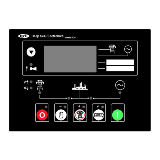
5.4 UNIT DIMENSIONS AND REAR PANEL LAYOUT Mounting holes suitable for 4 x 4mm screws 5.5 FRONT PANEL LAYOUT 057-001 720 Operating Instructions Issue 3.1 20/12/2005 - 17 -... -
Page 18: Electrical Connections
NOTE:- The Close Mains Slave relay should be NORMALLY CLOSED when de- energised for fail safe reasons. Should the DC supply fail the mains will always be available. The output from the DSE solid state output will energise to OPEN the relay and isolate the mains supply from the load. -
Page 19: Connector B
6.2 ORDERING REPLACEMENT CONNECTORS FROM DSE Connector Description DSE Part No. A (1-13) BL13 PCB connector 5.08mm plug 007-104 B (14-22) BL08 PCB connector 5.08mm plug 007-125 C (23-27) BL06 PCB connector 7.62mm plug 007-432 057-001 720 Operating Instructions Issue 3.1 20/12/2005 - 19 -... -
Page 20: Specification
Applicable Standards Compliant with BS EN 60950 Low Voltage Directive Compliant with BS EN 50081-2: 1992 EMC Directive Compliant with BS EN 61000-6-4: 2000 EMC Directive Compliance to European Legislation - 20 - 057-001 720 Operating Instructions Issue 3.1 20/12/2005... -
Page 21: Commissioning
If despite repeated checking of the connections between the 720 and the customer’s system, satisfactory operation cannot be achieved, then the customer is requested to contact the factory for... -
Page 22: Fault Finding
NOTE:- All the outputs are solid state and switch to battery positive when active. - 22 - 057-001 720 Operating Instructions Issue 3.1 20/12/2005... -
Page 23: Typical Wiring Diagram
10 TYPICAL WIRING DIAGRAM 057-001 720 Operating Instructions Issue 3.1 20/12/2005 - 23 -... -
Page 24: Solid State Outputs
To Positive supply via fuse To Fuel Solenoid Example of relay pins connected to DSE solid state output to drive a fuel solenoid. NOTE:- The Close Mains Relay should be NORMALLY CLOSED when de-energised for fail safe operation. Should the DC supply fail the mains will always be available. The output from the DSE solid state output when energised will OPEN the relay therefore isolating the mains supply. - Page 25 <<< THIS PAGE INTENTIONALLY BLANK >>> 057-001 720 Operating Instructions Issue 3.1 20/12/2005 - 25 - http://bestgenerator.spb.ru/?page_id=6765...
Need help?
Do you have a question about the 720 and is the answer not in the manual?
Questions and answers
Motor çalışıyor hızı kontrol edemiyor.
Possible causes for the DSE 720 motor to run but not control its speed include:
- Engine overspeed or underspeed conditions: If the engine speed exceeds or drops below preset trip levels after the Safety On timer expires, a shutdown is initiated.
- Faulty engine speed sensor or wiring issues: Incorrect speed signals can prevent proper control.
- Misconfigured or faulty switches related to engine temperature or oil pressure.
- Incorrect input wiring or configuration for inputs 1 and 2, if used for speed-related shutdowns.
- Safety timer settings that delay or extend overspeed trip limits during startup, possibly masking issues temporarily.
Check engine speed settings, sensor function, and wiring.
This answer is automatically generated