Table of Contents
Advertisement
Quick Links
Download this manual
See also:
User Manual
User's
Model UT150L
Limit Controller
Manual
Please read through this user's manual to ensure correct usage of the controller and keep it handy for quick reference.
Contents
1.
Notice ....................................................................... 1
2.
What is on the Front Panel? ..................................... 1
3.
Installing the Controller ............................................ 1
4.
Panel Cutout Dimensions and External
Dimensions .............................................................. 1
5.
Wiring ....................................................................... 2
6. Hardware Specifications .......................................... 2
7.
Key Operations (Parameter Settings) ...................... 2
8.
Limit Control Function .............................................. 4
9.
Troubleshooting ........................................................ 4
■ Checking Package Contents
Before using the product, check that its model & suffix codes are as you ordered.
Model and Suffix Codes
Model
Suffix code
UT150L
Limit Controller (1/16 DIN size)
−R
Relay output (time-proportional PID or on/off control)
Control
output
N
Always N
/AL
Alarm outputs (2 points)
/EX
Digital input (1 point)
Option
/RET
PV retransmission output in 4 to 20mA
/RS
Communication function
Check the package contents against the list below.
• Limit controller .............................. 1
• Mounting bracket ............ 1 for UT150L
• User's manual (IM 05C01E22-01E) ... 1
1.
Notice
The following safety symbol is used both on the product and in this user's manual.
WARNING
This symbol stands for "Handle with Care." When displayed on the product, the
operator should refer to the corresponding explanation given in the user's manual in
order to avoid injury or death of personnel and/or damage to the product. In the manual
the symbol is accompanied by an explanation of the special care that is required to
avoid shock or other dangers that may result in injury or loss of life.
The following symbols are used in this manual only.
CAUTION
Indicates that operating the hardware or software in a particular manner may lead to
damage or result in system failure.
IMPORTANT
Draws attention to information that is essential for understanding the operation and/or
features of the product.
■ Exemption from Responsibility
Make sure that all of the precautions are strictly adhered to. Yokogawa Electric Corporation assumes
no liability for any damage resulting from use of the instrument in contradiction to the precautions.
Also, Yokogawa Electric Corporation assumes no liability to any party for any loss or damage, direct
or indirect, caused by the use or any unpredictable defect of the instrument.
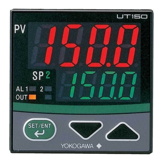
2.
What is on the Front Panel ?
c.
e.
d.
f.
i.
Name
Indicates PV (measured value) and character information such as parameter
a. PV display (red)
codes and error codes.
b. SP display (green)
Indicates SP (target setpoint) and parameter values.
c. EXCEEDED lamp (green)
Lit while PV is exceeding SP value.
d. Alarm 1 (AL1) lamp (red)
Lit when alarm 1 is activated.
e. Alarm 2 (AL2) lamp (red)
Lit when alarm 2 is activated.
• L it when PV exceeds SP value. This lamp does not go out until "confirming
f. Output (OUT) display lamp
operation" is done (see Page 4).
Note: Output relay contact is off when OUT lamp lights.
• Pressing the key for 1 second or longer in "operating display or "
puts out Output (OUT) display lamp. (This operation is the "confirming
operation".)
Reset/Data change (up) key
• P ressing the key for 1 second or longer in "confirmation display" resets
g.
"exceeded status (PV exceeds SP value)", "duration time" or max./min. PV
value those UT150L observed before.
• Pressing the key increases the data value.
Holding down the key will gradually increase the speed of change.
Data change (down) key
• Pressing the
h.
Holding down the key will gradually increase the speed of change.
• Registers the data value changed using the data change keys.
SET/ENT key (data registering
• Switches between parameter setting displays sequentially.
key)
• Pressing the key for 3 seconds or longer in the operating display retrieves
i.
(Indicated as simply the
key
the operating parameter setting display.
hereafter.)
• Pressing the key for 3 seconds or longer in either an operating or setup
parameter setting display transfers back to the operating display .
Revision Record
IM 05C01E22-01E 1st Edition: Oct. '00
2nd Edition: Feb. '01
3rd Edition: Mar. '01
4th Edition: Jun. '04
5th Edition: Sep. '04
6th Edition: Apr. '05
7th Edition: Mar. '16
IM 05C01E22-01E
1st Edition Oct. 2000 (YK)
7th Edition Mar. 2016 (YK)
Description
a.
b.
h.
g.
Function
key decreases the data value.
2-9-32, Naka-cho Musashino-shi, Tokyo 180-8750 Japan
Phone: +81-422-52-7179
You can download the latest manuals from the following website:
http://www.yokogawa.com/ns/ut/im/
•
Authorised Representative in the EEA
Yokogawa Europe BV. (Address: Euroweg 2 , 3825 HD Amersfoort, The Netherlands) is
the Authorised Representative of Yokogawa Electric Corporation for this Product in the
EEA.
•
Printed Manuals
Model UT150L Limit Controller (IM 05C01E22-01E)
Model UT150L Limit Controller Communication Functions (IM 05C01E22-10E)
•
General Specifications
Model UT150L Limit Controller (GS 05C01E22-01E)
3.
Installing the Controller
WARNING
● To prevent electric shock, the source of power to the controller must be turned off
when mounting the controller on to a panel.
● Since the controller is not of explosion-proof type, do not use this controller in
combustible or explosive gas atmospheres.
CAUTION
To install the controller, select a location where:
1. No-one may accidentally touch the terminals;
2. Mechanical vibrations are minimal;
3. Corrosive gas is minimal;
4. The temperature can be maintained at about 23°C
with minimal fluctuation;
5. There is no direct heat radiation;
6. There are no resulting magnetic disturbances;
7. The terminal board (reference junction
compensation element, etc.) is protected from wind;
8. There is no splashing of water; and
9. T here are no flammable materials.
Never place the controller directly on flammable items.
If the controller has to be installed close to flammable items or
equipment, be sure to enclose the controller in shielding panels
positioned at least 150mm away from each side. These panels
should be made of either 1.43mm thick metal-plated steel plates
or 1.6mm thick uncoated steel plates.
■ Mounting the Controller
Panel
1. Affix the bracket over the back
end of the controller.
UT150L
Bracket
[How to remove the bracket]
To move the bracket, push down the center of the upper and lower parts of the controller softly.
The bracket is released from the latch.
4.
Panel Cutout Dimensions and External Dimensions
1. General Mounting
min. 70
+0.6
25
45
0
48
Panel thickness
1 to 10
1
Facsimile: +81-422-52-6793
● Mount the controller at an angle
within 30° from horizontal with
the screen facing upward. Do not
mount it facing downward.
150mm
150mm
2. Push the bracket to the panel,
and then secure the bracket
into position.
2. Side-by-side Close Mounting
(Splash-proof construction is unavailable)
×
+
[(N –1)
48
45]
+0.6
0
N is the number of controllers.
If N > 5, then measure the actual length.
12
100
30° (MAX)
150mm
150mm
Unit: mm
Advertisement
Table of Contents

Related Manuals for YOKOGAWA UT150L


Summary of Contents for YOKOGAWA UT150L
- Page 1 Also, Yokogawa Electric Corporation assumes no liability to any party for any loss or damage, direct or indirect, caused by the use or any unpredictable defect of the instrument.
- Page 2 Input type operation, the controller shows the code (°C) code (°F) Always fix a terminal cover bracket to the UT150L limit controller before wiring if an optional anti- operating display Unspecified electric-shock terminal cover (part number: L4000FB) is used.
- Page 3 ■ Changing Setpoint (SP) Power ON CAUTION Step 1: Confirm that the controller shows the operating display When measured input range code has been already set, the operating display 1 shown below appears. or during normal is displayed operation.
- Page 4 ■ Description of Parameters ■ Duration Time (Refer to the confirmation display in the flowchart on page 3) This section describes the parameter functions specific to the UT150L limit controller. (The functions The time while PV exceeds SP is counted and stored in the memory. It is displayed in the “TIME” in described in other sections of this manual and the general functions are not discussed.) the confirmation display .
Need help?
Do you have a question about the UT150L and is the answer not in the manual?
Questions and answers