
Related Manuals for YOKOGAWA NEW GREEN Series


Summary of Contents for YOKOGAWA NEW GREEN Series
- Page 1 User’s Manual Models UT450/UT420 Digital Indicating Controllers User’s Manual IM 05D01C12-41E IM 05D01C12-41E 4th Edition...
- Page 2 Blank Page...
-
Page 3: Introduction
(2) Read this manual carefully to gain a thorough understanding of how to operate this product before starting operation. (3) This manual describes the functions of this product. Yokogawa Electric Corporation (hereinafter simply referred to as Yokogawa) does not guarantee the application of these functions for any particular purpose. - Page 4 I Force Majeure (1) Yokogawa assumes no liability to any party for any loss or damage, direct or indirect, caused by the use or any unpredictable defect of the product. (2) No portion of the software supplied by Yokogawa may be transferred, exchanged, leased or sublet for use by any third party without the prior permission of Yokogawa.
- Page 5 (1) In order to protect the product and the system controlled by it against damage and ensure its safe use, make certain that all of the instructions and precautions relating to safety contained in this document are strictly adhered to. Yokogawa does not guaran- tee safety if products are not handled according to these instructions.
- Page 6 Blank Page...
-
Page 7: Table Of Contents
Toc-i <Int> <Rev> Models UT450/UT420 Digital Indicating Controllers User’s Manual IM 05D01C12-41E 4th Edition CONTENTS Introduction......................i Installation ....................1-1 Model and Suffix Codes .................. 1-1 How to Install ....................1-2 How to Connect Wires ..................1-5 Hardware Specifications ................1-7 Terminal Wiring Diagrams ................ - Page 8 Toc-ii <Int> <Rev> Troubleshooting and Maintenance ............4-1 Troubleshooting ....................4-1 Maintenance ....................4-6 4.2.1 Cleaning ................... 4-6 4.2.2 Replacing Brackets ................4-6 4.2.3 Attaching Terminal Cover ..............4-7 4.2.4 Replacing Parts with a Limited Service Life ........4-8 4.2.5 Replacing Control Output Relays ............
-
Page 9: Installation
<Toc> <1. Installation> Installation This chapter describes installation, wiring, and other tasks required to make the controller ready for operation. Model and Suffix Codes Before using the controller, check that the model and suffix codes match your order. Model Suffix Code Description UT450 Digital indicating controller (provided with retransmission output and 15 V... -
Page 10: How To Install
<Toc> <1. Installation> How to Install NOTE To install the controller, select a location where: no one may accidentally touch the terminals, mechanical vibrations are minimal, 150 mm corrosive gas is minimal, temperature can be maintained at about 23 C and 150 mm 150 mm the fluctuation is minimal,... - Page 11 "N" stands for the number of controllers to be installed. However, the measured value applies if N +0.8 +0.8 (25) UT420 Unit: mm Small bracket YOKOGAWA REM MAN SET/ENT A / M Small bracket 1 to 10 mm (Panel thickness) General installation Side-by-side close installation 70 min.
- Page 12 <Toc> <1. Installation> I How to Install Turn off the power to the controller before installing it on the panel because there is a possibility of electric shock. CAUTION After opening the mounting hole on the panel, follow the procedures below to install the controller: Insert the controller into the opening from the front of the panel so that the terminal board on the rear is at the far side.
-
Page 13: How To Connect Wires
<Toc> <1. Installation> How to Connect Wires Before carrying out wiring, turn off the power to the controller and check that the cables to be connected are not alive with a tester or the like because there is a possi- bility of electric shock. - Page 14 Power supply, grounding, relay contact outputs 600 V PVC insulated wires, JIS C 3307, 0.9 to 2.0 mm Thermocouple Shielded compensating lead wires, JIS C 1610, (See Yokogawa Electric's GS 6B1U1-E.) Shielded wires (three conductors), UL2482 (Hitachi Cable) Other signals Shielded wires...
-
Page 15: Hardware Specifications
<Toc> <1. Installation> Hardware Specifications PV Input Signals • Number of inputs: 1 (terminals • Input type: Universal input system. The input type can be selected with the software. • Sampling period: 200 ms • Burnout detection: Functions at TC, RTD, standard signal (0.4 to 2 V or 1 to 5 V) Upscale, downscale, and off can be specified. - Page 16 <Toc> <1. Installation> Feedback Resistance Input Provided for position proportional type only (terminals • Slide resistance value: 100 to 2.5 k of overall resistance (burnout detection for sliding wire provided) • Measuring resolution: 0.1% of overall resistance Loop Power Supply Power is supplied to a two-wire transmitter.
- Page 17 <Toc> <1. Installation> • Relay contact output (Standard type: terminals , heating-side: terminals , cooling-side: terminals , position proportional type: terminals Number of outputs 1 or 2 (two for heating/cooling type) Output signal Three terminals (NC, NO, and common) Contact rating 250 V AC or 30 V DC, 3 A (resistance load) Resolution 10 ms or 0.1% of output, whichever is larger...
- Page 18 1-10 <Toc> <1. Installation> Display Specifications • PV display: UT450 5-digit, 7-segment, red LEDs, character height of 20 mm UT420 5-digit, 7-segment, red LEDs, character height of 12 mm • Setpoint display: 3-digit and 5-digit, 7-segment, red LEDs, character height of 9.3 mm (for both UT450 and UT420) •...
- Page 19 1-11 <Toc> <1. Installation> Construction, Installation, and Wiring • Construction: Dust-proof and drip-proof pront panel conforming to IP55. For side-by- side close installation the controller loses its dust-proof and drip-proof protection. • Material: ABS resin and polycarbonate • Case color: Black •...
- Page 20 1-12 <Toc> <1. Installation> Signal Isolations • PV input terminals: Isolated from other input/output terminals. Not isolated from the internal circuit. • Remote input terminals: Isolated from other input/output terminals and the internal circuit. • 15 V DC loop power supply terminals: Not isolated from 4-20 mA analog output nor voltage pulse control output.
- Page 21 1-13 <Toc> <1. Installation> Environmental Conditions • Normal operating conditions: Ambient temperature: 0 to 50 C (40 C or less for side-by-side close installation) Temperature change rate: 10 C /h or less Ambient humidity: 20 to 90% RH (no condensation allowed) Magnetic field: 400 A/m or less Continuous vibration at 5 to 14 Hz: Full amplitude of 1.2 mm or less Continuous vibration at 14 to 150 Hz: 4.9 m/s...
-
Page 22: Terminal Wiring Diagrams
1-14 <Toc> <1. Installation> Terminal Wiring Diagrams NOTE Do not use unassigned terminals as relay terminals. Terminal wiring diagrams are shown on and after the next page. IM 05D01C12-41E 4th Edition: May 31, 2006-00... -
Page 27: Initial Settings
<Toc> <2. Initial Settings> Initial Settings This chapter describes examples of setting PV input types, control output types, and alarm types. Carrying out settings described herein allows you to perform basic control. Refer to examples of various settings to understand how to set parameters required. -
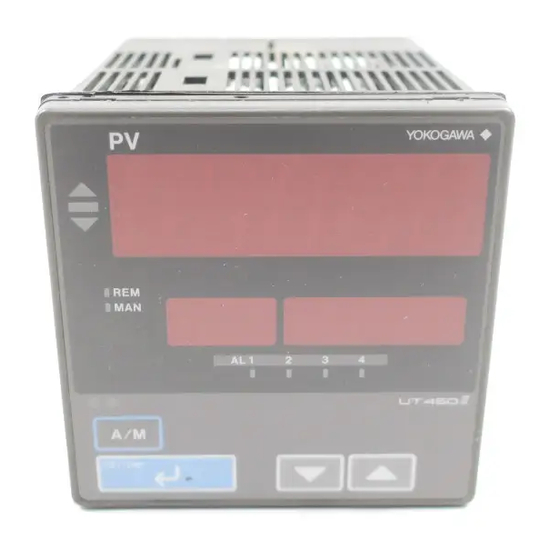
Page 28: Names And Functions Of Front Panel Parts
<Toc> <2. Initial Settings> Names and Functions of Front Panel Parts 4. Process YOKOGAWA 4. Process 5. Setpoint 1. Deviation variable (PV) variable (PV) display monitor display display 2. Status indicator 3-digit LED REM MAN 5. Setpoint 2. Status lamps... -
Page 29: Setting Pv Input Type (Setting First At Power-On)
<Toc> <2. Initial Settings> Setting PV Input Type (Setting First at Power-on) NOTE • The controller displays the operating display when the power is turned on. However, if PV input type has not been set, “IN” appears. In this case, first use the key to display the input range code to use, then press the key to register it. - Page 30 <Toc> <2. Initial Settings> Press the key once to register the Press the key once to display the SET/ENT SET/ENT required setpoint. parameter “RL” (minimum value of PV input range). M A N Displays M A N parameter A / M “RL”.
- Page 31 <Toc> <2. Initial Settings> I Instrument Input Range Codes Select the unit from the UNIT parameter. Instrument Input Instrument Input Type Measurement Accuracy Range Code Input Range Set the data item PV Input Type "IN" to the OFF option to leave the PV input Unspecified type undefined.
- Page 32 <Toc> <2. Initial Settings> NOTE The controller may automatically initialize the registered operating parameter setpoints if any change is made to the data item PV Input Type (IN), Maximum Value of PV Input Range (RH), Minimum Value of PV Input Range (RL), PV Input Decimal Point Position (DP), Maximum Value of PV Input Scale (SH) or Minimum Value of PV Input Scale (SL).
-
Page 33: Changing Pv Input Type
<Toc> <2. Initial Settings> Changing PV Input Type The following operating procedure describes an example of changing the setting of K-type thermocouple (-200.0 to 500.0 C) to RTD Pt100 (-200.0 to 500.0 C) and a measurement range of 0.0 to 200.0 C. PV input terminal Thermocouple/mV/V input...... - Page 34 <Toc> <2. Initial Settings> Press the key once to display the Press the key once to display the SET/ENT SET/ENT parameter “UNI”. parameter “RL” (minimum value of PV input range). M A N Displays M A N parameter A / M SET/ENT “RL”.
-
Page 35: Setting Control Output Type (Except For A Position Proportional Controller)
<Toc> <2. Initial Settings> Setting Control Output Type (except for a Position Proportional Controller) The following operating procedure describes an example of changing time proportional PID relay output (0: factory-shipped value) to current output (2). Control output terminal Values in parentheses are setpoints Time proportional PID relay (0)/on-off(3) output...... - Page 36 2-10 <Toc> <2. Initial Settings> Press the key to display the Press the key for more than 3 sec- SET/ENT required setpoint. The figure below shows onds. This returns you to the display an example of setting to current output (4 shown at power-on (figure below).
-
Page 37: Calibrating Valve Position (For A Position Proportional Controller Only)
2-11 <Toc> <2. Initial Settings> Calibrating Valve Position (for a Position Proportional Controller Only) The following operation describes a procedure of inputting a feedback signal from a control valve to calibrate the full closed and full open positions of the valve automatically. To cali- brate the valve position, you need to carry out wire connections and bring the controller into manual mode. -
Page 38: Initializing Parameters
2-12 <Toc> <2. Initial Settings> The controller is viewed as shown below Press the key for more than 3 sec- SET/ENT when the valve position is being automati- onds. This returns you to the display cally calibrated. shown at power on (figure below). The indication Displays PV. -
Page 39: Changing Alarm Type
2-13 <Toc> <2. Initial Settings> Press the key once to display the Press the key to display “ON”. menu “STUP”. Blinks during change. Displays M A N menu “STUP”. M A N SET/ENT A / M SET/ENT Press the key once. The display SET/ENT Press the key once to display the... - Page 40 2-14 <Toc> <2. Initial Settings> Bring the operating display into view Press the key once to display the SET/ENT (display appears at power on). parameter “AL1” (alarm-1 type). Displays Displays PV. Displays M A N target setpoint-1 parameter “1.SP”. “AL1”. A / M A / M SET/ENT...
- Page 41 2-15 <Toc> <2. Initial Settings> I List of Alarm Types The table below shows the alarm types and alarm actions. In the table, codes 1 to 10 are not provided with stand-by actions, while codes 11 to 20 are provided with stand-by actions. Alarm type code Alarm type code Alarm action...
-
Page 42: Description Of Multiple Setpoints And Pid
2-16 <Toc> <2. Initial Settings> Stand-by Action Normal Abnormal Treated The alarm as normal output turns on. Low limit of alarm setpoint The alarm output does not turn on in this region even It is effective in the following cases where; if the PV value is below the - the power is turned on low limit of the alarm setpoint. -
Page 43: Operations
<Toc> <3. Operations> Operations This chapter describes key entries for operating the controller. For operations using external contact inputs, see “1.5 Terminal Wiring Diagrams.” If you cannot remem- ber how to carry out an operation during setting, press the key for more than 3 SET/ENT seconds. - Page 44 <Toc> <3. Operations> I Operating Displays for a Heating/Cooling Controller G SP Display The PV input value appears on the PV display. The target setpoint (1.SP) appears on the Setpoint display. (can be changed) G Heating/Cooling OUT Display The PV input value appears on the PV display. The heating and cooling sides control output value (C.H) appears on the Setpoint display.
-
Page 45: Setting Target Setpoint (Sp)
<Toc> <3. Operations> Setting Target Setpoint (SP) The following operating procedure describes an example of setting 150.0 to a target setpoint. In automatic operation, the controller starts control using set target setpoints. Bring the operating display into view Press the key once to register the SET/ENT (display appears at power on). - Page 46 <Toc> <3. Operations> Bring the operating display into view Press the key to display the (display appears at power on). required setpoint. Tuning for 1.SP is AT = 1. MAN lamp OFF. Blinks during Displays PV. change. M A N M A N Displays target setpoint-1...
-
Page 47: Setting Pid Manually
<Toc> <3. Operations> Setting PID Manually If you know the values to be set or if suitable PID constants cannot be obtained by auto- tuning, follow the procedure below to set values. Bring the operating display into view Press the key once to register the SET/ENT (display appears at power on). -
Page 48: Setting Alarm Setpoints
<Toc> <3. Operations> [TIP] Press the key for more than 3 sec- SET/ENT The PID parameter numbers set in step 4. onds. This returns you to the display should be set as follows: shown at power-on (figure below). In case of PID for 1.SP, PID = 1Gr In case of PID for 2.SP, PID = 2Gr In case of PID for 3.SP, PID = 3Gr In case of PID for 4.SP, PID = 4Gr... -
Page 49: Selecting Target Setpoint Numbers (Spn)
<Toc> <3. Operations> Press the key once to register the Press the key for more than 3 sec- SET/ENT SET/ENT setpoint. onds. This returns you to the display shown at power-on (figure below). M A N Displays PV. Displays M A N target setpoint-1 “1.SP”. -
Page 50: Switching Between Run And Stop
<Toc> <3. Operations> Press the key once to register the Press the key for more than 3 sec- SET/ENT SET/ENT setpoint. onds. This returns you to the display shown at power-on (figure below). M A N Displays Displays PV. M A N target setpoint-2 “2.SP”. -
Page 51: Switching Between Auto And Man
<Toc> <3. Operations> The following display is used to view the Press the key once to register the SET/ENT output value when the controller is in STOP setpoint. (OUT display). Displays a fixed (preset) M A N Displays output value. M A N symbol “STP”. -
Page 52: Manipulating Control Output During Manual Operation
3-10 <Toc> <3. Operations> Each time you press the key on the front panel of the instrument, AUTO and MAN is switched alternately. In automatic operation In manual operation MAN lamp MAN lamp Target OFF. Output value setpoint M A N M A N Displays Displays... - Page 53 3-11 <Toc> <3. Operations> I Manipulating the Control Output during Heating/Cooling Control Showing the Heating/Cooling OUT display. MAN lamp ON. SET/ENT Heating/Cooling OUT display Cooling-side Heating-side output output Symbol “C” Symbol “H” represents the represents the cooling-side heating-side output output G Controller Behavior and Control Output Manipulation when the Dead Band is Positive The following is an example when the DB parameter is set at 12.4%.
-
Page 54: Switching Between Remote (Rem) And Local (Lcl)
3-12 <Toc> <3. Operations> G Controller Behavior and Control Output Manipulation when the Dead Band is Negative The following is an example when the DB parameter is set at -12.4%. If you hold down the key with the heating-side output under manipulation (i.e., cooling- side output C = 0.0%), the heating-side output (H =) decreases. - Page 55 3-13 <Toc> <3. Operations> G Local Performs control using target setpoints set in the controller. G Remote Performs control using external analog signals as target setpoints. PV input Remote input (analog signal) Local Remote (LCL) (REM) Control output Note: The PID group number when the controller is in Remote operation is the same as the number set in the Target Setpoint Number (SPN) parameter.
- Page 56 Blank Page...
-
Page 57: Troubleshooting And Maintenance
<Toc> <4. Troubleshooting and Maintenance> Troubleshooting and Maintenance Troubleshooting I Troubleshooting Flow If the operating display does not appear after turning on the controller’s power, follow the measures in the procedure below. If a problem appears complicated, contact our sales representative. Is the instrument defective? Is key... - Page 58 <Toc> <4. Troubleshooting and Maintenance> I Errors at Power on The following table shows errors that may be detected by the fault diagnosis function when the power is turned on. Error indication Description Control Alarm Retransmission Communi- Remedy (on PV display unit) of error output output...
- Page 59 <Toc> <4. Troubleshooting and Maintenance> I Possible Errors during Operation The following shows possible errors occurring during operations. Error indication Description Alarm Retransmis- Commu- Control output Remedy (on PV display unit) of error output sion output nication Displays “RJC” and Measured RJC error PV alternately...
- Page 60 <Toc> <4. Troubleshooting and Maintenance> G Power Failure of more than about 2 seconds The following show effects caused in “settings” and “operation status.” Alarm action Continues. Alarm with standby function will enter standby status. Setting parameter Set contents of each parameter are retained. Auto-tuning Cancelled.
- Page 61 <Toc> <4. Troubleshooting and Maintenance> I Troubleshooting when the Controller Fails to Operate Correctly If your control tasks are not successful, check the preset parameters and controller wiring before concluding the controller to be defective. The following show some examples of troubleshooting you should refer to in order to avoid the possibility of other problems.
-
Page 62: Maintenance
<Toc> <4. Troubleshooting and Maintenance> Maintenance This section describes the cleaning and maintenance of the UT450/UT420. 4.2.1 Cleaning The front panel and operation keys should be gently wiped with a dry cloth. NOTE Do not use alcohol, benzine, or any other solvents. 4.2.2 Replacing Brackets When the brackets are broken or lost, purchase the following brackets for replacement. -
Page 63: Attaching Terminal Cover
<Toc> <4. Troubleshooting and Maintenance> 4.2.3 Attaching Terminal Cover When a terminal cover is necessary, purchase the following part. Target Model Part No. Sales Unit UT450 T9115YD UT420 T9115YE I Attaching Terminal Cover The procedure for attaching the terminal cover is as follows. Do not touch the terminals on the rear panel when power is being supplied to the controller. -
Page 64: Replacing Parts With A Limited Service Life
<Toc> <4. Troubleshooting and Maintenance> With the cover properly folded, fit its top and bottom holes to the protrusions of the mounting brackets. Fit the hole of the terminal cover to the protrusion on the mounting bracket. Attaching Terminal Cover 4.2.4 Replacing Parts with a Limited Service Life The following UT450/UT420 parts have a limited service life. -
Page 65: Replacing Control Output Relays
This subsection describes how to replace the control output relays. Since inspection is needed in case parts are replacement will be carried out by a YOKOGAWA engineer or an engineer certified by YOKOGAWA. When replacement is required, contact your nearest YOKOGAWA dealer. - Page 66 4-10 <Toc> <4. Troubleshooting and Maintenance> Hold the bezel and pull it along with the internal unit out of the housing. (Note) Be careful not to damage the RJC sensor. The location and number of the relays differ depending on the model code of the UT450/ UT420.
- Page 67 4-11 <Toc> <4. Troubleshooting and Maintenance> Insert the internal unit into the housing. Apply power to the controller and confirm that the initial operating display is shown. If the operating display is not shown properly, turn off the controller and pull out the internal unit.
- Page 68 Blank Page...
-
Page 69: Parameters
<Toc> <5. Parameters> Parameters Parameter Map This section contains a parameter map as a guideline for setting parameters. These maps helpful in finding the positions of the displays when setting the parameters, and should be used as a quick reference for the entire range of parameter displays. IM 05D01C12-41E 4th Edition: May 31, 2006-00... - Page 70 <Toc> <5. Parameters> UT450/UT420 Operating Parameter Map Operating Display OUT display or OUT display PID number Operating SELECT SELECT SP display display n display 1 display 2 for heating/cooling control display SET3S SET3S Menu OP.PA To switch the parameter display, press the SET/ENT key.
- Page 71 <Toc> <5. Parameters> SET/ENT Press the key once. SET3S SET/ENT Press the key for 3 seconds. Press the key once. Press the keys simultaneously. SELECT display 5 STUP Displayed only when password registration Password Password input check display (No password is required when PWD = 0.) Not displayed with factory-shipped settings To use 5.SP to 8.SP,...
- Page 72 <Toc> <5. Parameters> UT450/UT420 Setup Parameter Map Password To operating parameter check display setting display menu [OP.PA] (on the previous page) Menu Target Control action Retransmission setpoint Security Alarm related related output related related LOCK Parameters RMS and SPT are displayed only for controllers with remote input.
- Page 73 <Toc> <5. Parameters> SET/ENT Press the key once. Press the key once. Press the keys simultaneously. SELECT Input/output Parameter display related Communication Valve related initialization CSEL R485 VALV INIT Displayed first C.S1 V.AT after power on C.S2 V.RS Displayed in manual operation C.S3 C.S4...
-
Page 74: Lists Of Parameters
<Toc> <5. Parameters> Lists of Parameters This section describes the functions of parameters briefly. In addition, each parameter table has a “User Setting” column, where you can record your setpoints when setting them in the controller. * Parameters relating to PV or setpoints should all be set in real numbers. For example, use temperature values to define target setpoints and alarm setpoints for temperature input. - Page 75 <Toc> <5. Parameters> Parameter Target Item Name of Parameter Setting Range and Description Initial Value User Setting Symbol in CD-ROM Target setpoint 1. Selects target setpoint 1 (1.SP). 2. Selects target setpoint 2 (2.SP). number selection 3. Selects target setpoint 3 (3.SP). (SPN) 4.
- Page 76 <Toc> <5. Parameters> G PID-related Parameters The following parameters are displayed when “1Gr” is set to PID parameter display number (PID). In this case, the corresponding target setpoint is 1.SP (target setpoint-1). To set PID corresponding to target setpoint 2 to 4, set “2Gr”, “3Gr”, or “4Gr” to PID. The relevant parameters will then be displayed.
- Page 77 <Toc> <5. Parameters> Refer to the table below for recording setpoints when two sets or more of PID parameters are used. Parameter n.OH n.OL n.MR n.DR n.Pc n.Ic n.Dc n.Hc n.DB n.PO n.Oc IM 05D01C12-41E 4th Edition: May 31, 2006-00...
- Page 78 5-10 <Toc> <5. Parameters> I Setup Parameters G Target Setpoint-related Parameters Parameter Target Item Name of Parameter Setting Range and Description Initial Value User Setting Symbol in CD-ROM Remote input selection RSP (0): Remote setpoints are used via remote input RSP (0) (terminals).
- Page 79 5-11 <Toc> <5. Parameters> G Alarm-related Parameters Parameter Target Item Name of Parameter Setting Range and Description Initial Value User Setting Symbol in CD-ROM Alarm-1 type OFF (0), 1 to 31 Ref.3.3(3) (same as below) Ref.3.3(4) (AL1) Alarm-2 type OFF (0), 1 to 20, 25 to 31 1: PV high limit (energized, no stand-by action) Ref.3.3(4) (AL2)
- Page 80 5-12 <Toc> <5. Parameters> G Control Action-related Parameters Parameter Target Item Name of Parameter Setting Range and Description Initial Value User Setting Symbol in CD-ROM Output velocity limiter OFF (0) OFF (0) 0.1 to 100.0%/second. (OPR) can limit control output velocity PID control mode 0: Standard PID control (with output bump at SP change) 1: Fixed value control (without output bump at SP change)
- Page 81 5-13 <Toc> <5. Parameters> G Retransmission Output Parameters Parameter Target Item Name of Parameter Setting Range and Description Initial Value User Setting Symbol in CD-ROM Retransmission output OFF (0): Disable type 1: PV, 2: SP , 3: OUT 4: Loop power supply for sensor (15 V) (RET) In position proportional control, a valve opening signal Ref.2.2(1)
- Page 82 5-14 <Toc> <5. Parameters> G Input-/Output-related Parameters Parameter Target Item Name of Parameter Setting Range and Description Initial Value User Setting Symbol in CD-ROM PV input type (PV INPUT OFF (0), 1 to 18, 30, 31, 35 to 37, 40, 41, 50, 51, 55, 56 OFF (0) terminals) See Instrument Input Range Codes in...
- Page 83 5-15 <Toc> <5. Parameters> Parameter Target Item Name of Parameter Setting Range and Description Initial Value User Setting Symbol in CD-ROM Control output Time proportional PID relay contact output type (terminals Heating/cooling Time proportional PID voltage pulse output type: 4 (terminals 16 17 Current output (terminals...
- Page 84 5-16 <Toc> <5. Parameters> • External contact-based SP selection when DIS = 1 is set 1.SP 2.SP 3.SP 4.SP 5.SP 6.SP 7.SP 8.SP • SP selection when DIS = 4 is set 1.SP 2.SP 3.SP 4.SP G Communication Parameters Parameter Target Item Name of Parameter Setting Range and Description...
- Page 85 5-17 <Toc> <5. Parameters> G Motor-driven Valve Calibration-related Parameters (Displayed for Position Proportional Controllers) Parameter Target Item Name of Parameter Setting Range and Description Initial Value User Setting Symbol in CD-ROM Automatic valve Automatically adjusts the fully-closed and fully-open OFF (0) adjustment positions of a valve.
- Page 86 Blank Page...
-
Page 87: Function Block Diagram And Descriptions
<Toc> <6. Function Block Diagram and Descriptions> Function Block Diagram and Descriptions This chapter contains the function block diagrams for “Standard Type,” “Heating/ Cooling Type,” and “Position Proportional Type.” For details on these function block diagrams, refer to the descriptions mentioned later. In the function block diagram for “Standard Type,”... - Page 88 <Toc> <6. Function Block Diagram and Descriptions> I Function Block Diagram for Standard Type (UT450/UT420) PV input Remote input Communication terminals terminals terminals Contact input PV INPUT RS485 INPUT Input selection Input selection Unit selection Input range conversion Input range conversion Input bias Input filter Remote setting filter...
- Page 89 <Toc> <6. Function Block Diagram and Descriptions> I Function Block Diagram for Heating/Cooling Type (UT450/UT420) PV input Remote input Communication terminals terminals terminals Contact input PV INPUT RS485 INPUT Input selection Input selection Unit selection Input range conversion Input range conversion Input bias Input filter Remote setting filter...
- Page 90 <Toc> <6. Function Block Diagram and Descriptions> I Function Block Diagram for Position Proportional Type (UT450/UT420) PV input Remote input Communication terminals terminals terminals Contact input PV INPUT RS485 INPUT Input selection Input selection Unit selection Input range conversion Input range conversion Input bias Input filter Remote setting filter...
- Page 91 <Toc> <6. Function Block Diagram and Descriptions> Functions and Parameters for “Standard Type” in Initial State (Factory-set default) Functions and parameters in initial state are given in the tables below. For details on each parameter, refer to “5.2 Lists of Parameters.” I PV Input PV input (PV INPUT) is a universal input, which can receive signals from a thermocouple or RTD, or DC voltage signals.
- Page 92 <Toc> <6. Function Block Diagram and Descriptions> I Contact Input Automatic (ON)/Manual (OFF) switching function is assigned to DI1 (contact input 1). Manipulated output can be changed using the keys in manual mode. Run (OFF)/Stop (ON) switching function is assigned to DI2 (contact input 2). Preset output value is output when the operation is stopped.
- Page 93 <Toc> <6. Function Block Diagram and Descriptions> The target setpoint ramp rate setting function prevents the target setpoint form changing suddenly. It is possible to set the upward and downward changing rate (i.e., ramp rate) independently in the parameters UPR and DNR. The unit of the ramp rate (hour, or minute) is specified in TMU.
- Page 94 <Toc> <6. Function Block Diagram and Descriptions> I Contact Output Alarm 1 is output via AL1 (contact output 1). Alarm 2 is output via AL2 (contact output 2). Alarm 3 is output via AL3 (contact output 3). Alarm 4 is output via AL4 (contact output 4). Setup Parameters Function Parameter...
-
Page 95: Revision Information
Jul. 2004/3rd Edition Change of the company name May 2006/4th Edition Revision by the change of safety standard description Written by Yokogawa Electric Corporation Published by Yokogawa Electric Corporation 2-9-32 Nakacho, Musashino-shi, Tokyo 180-8750, JAPAN IM 05D01C12-41E 4th Edition: May 31, 2006-00... - Page 96 Blank Page...
- Page 98 Sales Branch Offices / Houten (The Netherlands), Wien (Austria), Zaventem (Belgium), Ratingen (Germany), Madrid (Spain), Bratislava (Slovakia), Runcorn (United Kingdom), Milano (Italy), Velizy villacoublay(France), Johannesburg(Republic of South Africa) YOKOGAWA AMERICA DO SUL S.A. Headquarters & Plant Praca Acapulco, 31-Santo Amaro, Sao Paulo/SP, BRAZIL CEP-04675-190 Phone: +55-11-5681-2400 Facsimile: +55-11-5681-4434 YOKOGAWA ENGINEERING ASIA PTE.
Need help?
Do you have a question about the NEW GREEN Series and is the answer not in the manual?
Questions and answers