
Subscribe to Our Youtube Channel
Related Manuals for NOMA 052-8399-0


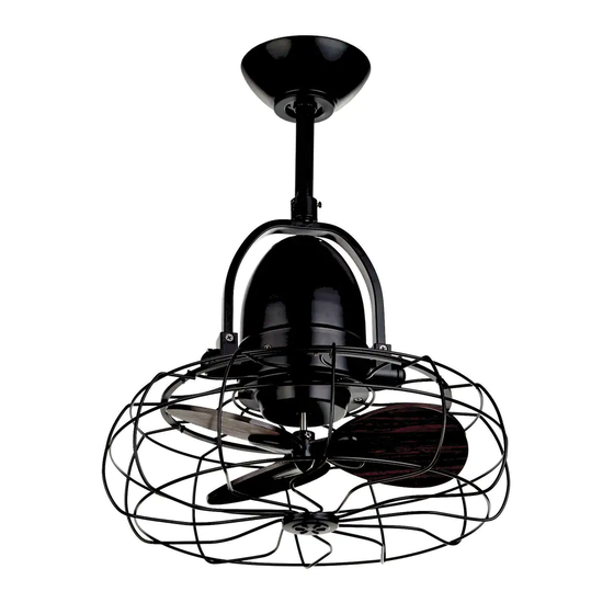
Summary of Contents for NOMA 052-8399-0
- Page 1 Oscillating Ceiling Fan model no. 052-8399-0 Toll-free 1-866-827-4985 IMPORTANT: For your safety please read and understand OWNER’S MANUAL this manual before installing or operating this product. V1.2016...
- Page 2 Toll Free 1-866-827-4985 model no. 052-8399-0 Safety Rules – Read and Save These Instructions 1. To reduce the risk of electric shock, ensure electricity has been t fuse box before beginning. 2. All wiring must be in accordance with the national and local electrical codes. Electrical installation should be performed by a qualified licensed electrician.
- Page 3 Tools Needed (not supplied) Required Flathead Crosshead Safety glasses screwdriver screwdriver Pliers Wire cutters Electrical t ape Step ladder Helpful Wire strippers Soft cloth...
-
Page 4: Unpacking Your Fan
Toll Free 1-866-827-4985 model no. 052-8399-0 Unpacking Your Fan Unpack and inspect fan carefully to be certain all contents are included. 1. Hanger Bracket 2. Canopy 3. Decorative Cap 4. Downrod Set (Included Octangle Hanger Ball, 6” Downrod, Hanger Pin & Lock Pin) 5. -
Page 5: Safety Instructions
Safety Instructions Read all safety information and installation instructions before you begin to install the fan and save instructions. All set screws of the fan must be checked and retightened where necessary before installation. 3. The safeguards provided by these safety instructions and by the separate installation instructions are not meant to cover all possible conditions and situations that may occur. - Page 6 Toll Free : 1-866-827-4985 model no. 052-8399-0 2.(1) Securely attach the mounting bracket to an outlet box marked “Acceptable for Fan Support ”, using the supplied outlet box Mounting screws with spring washers (Fig. 2a). Bracket Outlet Box Spring Washer (2) Drill two mounting holes in the ceiling joist.
- Page 7 Loosen the collar screws part way. Insert the downrod into the collar. Slide hanger pin through holes of collar and downrod (Fig. 5). Canopy Motor Wires Downrod Decorative Cap Hanger Pin Collar Fig. 5 6. Insert and tighten the two collar screws. Slide lock pin into hanger pin until it is locked into position (Fig.
- Page 8 Toll Free : 1-866-827-4985 model no. 052-8399-0 8. Make wire connections using wire nuts: (Fig. 8) Between fan and receiver: · Connect the black wire marked “L” from the fan to the black wire marked “TO MOTOR L” from the receiver.
- Page 9 Installing Receiver Assembly Once the connection has been made, the receiver inserts into the drop rod hanging bracket. The canopy comes up to cover the receiver and bracket . Lea ve unconnected and do not cut . VIEW AFTER INSTALLATION 9.
-
Page 10: Operation
Toll Free : 1-866-827-4985 model no. 052-8399-0 Operation 11. Turn on the electric circuit at the main fuse or circuit breaker box (Fig. 11). Fig. 11 12. Install the 9 V battery (included). To prevent damage to transmitter remove the battery if not used for long periods . -
Page 11: Maintenance
MAINTENANCE Because of the fan’s natural movement, some connections may become loose. Check the support connections, brackets and blade attachments twice a year. Ma ke sure they are secure. There is no need to oil your fan. The motor has permanently-lubricated bearings. CARE AND CLEANING Dust your fan periodically with a soft,dry cloth. -
Page 12: Environmental Protection
Toll Free : 1-866-827-4985 model no. 052-8399-0 TROUBLESHOOTING Problem Possible reason Solution Fan does . Fan is in reverse (blades are moving in . Counter-clockwise (forward) is not seem to recommended in warm weather. clockwise direction). move much air. rotation to stop. Use the eraser end of a pencil to change the forward/ reverse slide switch. -
Page 13: Care Of Your Fan
This product carries a limited ten (10) year warranty against defects in the motor, and a one (1) year warranty against defects in workmanship and materials. Noma Canada agrees to replace the defective product free of charge within the stated warranty period, when returned by the original purchaser with proof of purchase.
Need help?
Do you have a question about the 052-8399-0 and is the answer not in the manual?
Questions and answers