Table of Contents
Advertisement
Advertisement
Table of Contents

Subscribe to Our Youtube Channel
Related Manuals for K-array KA14


Summary of Contents for K-array KA14
- Page 1 Ver. 1.2 KA14 USER GUIDE English...
-
Page 2: Table Of Contents
KA14 Ver. 1.2 TABLE of CoNTENTS SYMBoLS ................3 1. INTRoDUCTIoN ..............4 2. KEY fEATURES ..............4 3. APPLICATIoNS ............... 4 4. SAfETY INfoRMATIoN ............5 5. UNPACKING ................. 6 6. INCLUDED ACCESSoRIES ............6 7. PhYSICAL ovERvIEw .............. 7 8. -
Page 3: Symbols
KA14 Ver. 1.2 SYMBoLS K-array declares that this device is in compliance with applicable CE standards and regulations. Before putting the device into operation, please observe the respective country-specific regulations! Waste Electrical and Electronic Equipment (WEEE) Please dispose of this product at the end of its operational lifetime by bringing it to your local collection point or recycling center for such equipment. -
Page 4: Introduction
The front panel has an easy-to-use touchscreen that gives access to all the basic functions for quick setup and corrections. The KA14 can be used as a mixer for fixed installations thanks to the XLR and RCA analog inputs. -
Page 5: Safety Information
KA14 Ver. 1.2 4. SAfETY INfoRMATIoN Read these instructions - Keep these instructions - Heed all warnings Warning: Failure to follow these safety instructions could result in fire, shock or other injury or damage to the device or other property. -
Page 6: Unpacking
5. UNPACKING 6. INCLUDED ACCESSoRIES Each K-array amplifier is built to the highest • Power cable standard and is thoroughly inspected before • USB cable leaving the factory. -
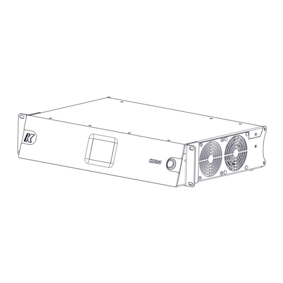
Page 7: Physical Overview
KA14 Ver. 1.2 7. PhYSICAL ovERvIEw 19in 481mm 17in 430mm Weight 3.8 kg (8.0 lbs) -
Page 8: Installation
8. INSTALLATIoN The KA14 is the height of two rack units (2U) and can be mounted in an EIA-standard 19’’ rack using two rack adapters (included). In case of installation on a flat surface, use the four rubber pads included. -
Page 9: Voltage And Current Requirements
5 VAC. 9.1 voLTAGE REQUIREMENT The KA14 accommodates AC mains power operating at either 115 V or 230 V. The amplifier will continue to operate safely, without interruption, provided the AC voltage remains within a nominal range of 100 - 240 V (operating range 85 - 264 V) at 50 to 60 Hz. -
Page 10: Back Panel
KA14 Ver. 1.2 10. BACK PANEL AC INPUT. Power socket IEC 320 C14. POWER ON LED. Indicates the amplifier is ON. XLR MIC/LINE INPUTS. Female balanced XLR analog inputs, with selectable sensitivity for Mic (-30 dBu) or Line (+4 dBu). These two inputs accept balanced, low impedance audio signals which allow the use of long cable runs (>10mt), without losing the quality of the signal. -
Page 11: Signal Flow
RCA OUT L KA14 Signal-flow The KA14 features two independent input processing channels (CH1 and CH2) and four independent output processing channels (A1, A2, B1, B2). The physical inputs (XLR 1, XLR 2, RCA L and RCA R) can be assigned to any input processing channel thanks to the Input Matrix . - Page 12 KA14 Ver. 1.2 The processing input channels CH1 and CH2 can be independently equalized via the K-framework software, then they can be routed to any output channel (A1, A2, B1, B2) thanks to the Output Matrix . The user can adjust the level of the four output channels independently. If necessary, the phase can be inverted on each output channel.
-
Page 13: Touch Screen Functions
KA14 Ver. 1.2 12. ToUCh SCREEN fUNCTIoNS The main functions of the onboard DSP can be managed with the integrated touch screen. Functions are grouped into six pages, shown as icons on the Home page. hoME PAGE To reach the homepage from any other page, touch the Home button. - Page 14 KA14 Ver. 1.2 DELAY The Delay page allows users to independently set the delays for the B1 and B2 output channels (up to 6 m). The delays are available on these outputs because they are often used to realign the subwoofers (connected to the B1 and B2 outputs) with the mid-high speakers (connected to the A1 and A2 outputs).
-
Page 15: Remote Control
KA14 Ver. 1.2 PRESET The Preset page allows users to load presets stored on-board. INfo The Info page contains information about the current software and firmware, and the Board ID of the amplifier. When connecting the amplifier in a K-framework network, please make sure that all devices in the network have different ID numbers. -
Page 16: Service
14. SERvICE To obtain service: 1) Contact the official K-array distributor in your country. Your local distributor will direct you to the appropriate service center. 2) If you are calling for service, please have the serial number(s) of the unit(s) available for reference. Ask for Customer Service, and be prepared to describe the problem clearly and completely. -
Page 17: Specifications
The contents of this manual are furnished for informational purposes only. K-array s.u.r.l. assumes no responsibility for any errors or inaccuracies that may appear in this manual. K-array s.u.r.l. reserves the right to make modifications without prior notice.
Need help?
Do you have a question about the KA14 and is the answer not in the manual?
Questions and answers