Table of Contents
Advertisement
Advertisement
Table of Contents

Subscribe to Our Youtube Channel
Related Manuals for K-array KA24


Summary of Contents for K-array KA24
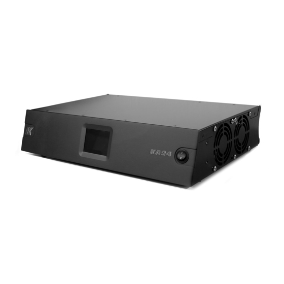
- Page 1 Ver. 1.2 KA24 - KA84 USER GUIDE English...
-
Page 2: Table Of Contents
KA24/KA84 Ver. 1.2 TABLE of CoNTENTS SYMBoLS ................3 1. INTRoDUCTIoN ..............4 2. KEY fEATURES ..............4 3. APPLICATIoNS ............... 4 4. SAfETY INfoRMATIoN ............5 5. UNPACKING ................. 6 6. INCLUDED ACCESSoRIES ............6 7. PhYSICAL ................7 8. -
Page 3: Symbols
KA24/KA84 Ver. 1.2 SYMBoLS K-array declares that this device is in compliance with applicable CE standards and regulations. Before putting the device into operation, please observe the respective country-specific regulations! WEEE Please dispose of this product at the end of its operational lifetime by bringing it to your local collection point or recycling center for such equipment. -
Page 4: Introduction
1. INTRoDUCTIoN The K-array KA line of power amplifiers are comprised of KA24 and KA84. The KA24 has 4 channels per 500W on 4Ω and the KA84 has 4 channels per 2000W on 4Ω. Each model has 4 fully independent and configurable channels. -
Page 5: Safety Information
KA24/KA84 Ver. 1.2 4. SAfETY INfoRMATIoN Read these instructions - Keep these instructions - Heed all warnings Warning. Failure to follow these safety instructions could result in fire, shock or other injury or damage to the device or other property. -
Page 6: Unpacking
5. UNPACKING 6. INCLUDED ACCESSoRIES Each K-array amplifier is built to the highest • Power cable 3 m standard and thoroughly inspected before leaving • USB cable 1.8 m... -
Page 7: Physical
KA24/KA84 Ver. 1.2 7. PhYSICAL 480 mm (18.9") 430 mm (16.9") Weight KA24: 5.5 Kg (12.12 lb) KA84: 6.1 Kg (13.45 lb) 304.8 mm (12.0") -
Page 8: Installation
Ver. 1.2 8. INSTALLATIoN KA24 and KA84 are two rack units high (2U) and can be mounted in an EIA-standard 19’’ rack using two rack adapters (included). In case of istallation on a flat surface, use the four rubber pads included. -
Page 9: Ac Power
9. AC PowER KA24 and KA84 operate safely and without audio discontinuity if the AC voltage stays within an operating range of 90 V to 264 V (nominal range: 100-240 V) at 50-60 Hz. Please verify that your AC main connections are capable of satisfying the power rating for the device. -
Page 10: Power Supply
CH 5 - 6 AC INPUT. PowerCon for AC power. AC LINK. PowerCon ouput for feeding AC mains power to additional K-array components with a powercon AC input socket. POWER ON LED. Indicates the amplifier is ON. 11.2 AUDIo CoNNECTIoNS CH 1 MIC/LINE INPUT. -
Page 11: Remote Control
Users can manage an entire network of RS485 devices with one PC connected via USB. EXTENSION CONNECTOR. Multi-pin connector for various K-array extension modules, for wireless control and audio transmission, memory extension, digital signal encoding and audio reproduction. - Page 12 KA24/KA84 Ver. 1.2 USB connection from a PC CH 5 - 6 RS485 XLR LINK CH 5 - 6 RS485 XLR LINK CH 5 - 6 Next device in the K-framework network RS485 network...
-
Page 13: Bridge Mode
(A1 and A2 or B1 and B2). In the Matrix Page, send the same signal to both outputs. On the KA24 take the signal from 2+ (positive) 1- (negative). On the KA84 take the signal from 1+ (positive) 2- (negative). -
Page 14: Touch Screen Functions
KA24/KA84 Ver. 1.2 12. ToUCh SCREEN fUNCTIoNS The main functions of the onboard DSP can be managed with the integrated touch screen. Functions are grouped into six pages, shown as icons on the Home page. hoME PAGE To reach the Home page from any other page, touch the Home button. - Page 15 KA24/KA84 Ver. 1.2 DELAY The Delay page allows users to independently set the delays for the four output channels (up to 3.5 mt) and for Channel 3 and Channel 4 input channels (up to 114 mt). Pressing on a delay value, users can set the delay in ms or in mt.
-
Page 16: Remote Control Software
KA24/KA84 Ver. 1.2 PRESET The Preset page allows users to load presets stored on-board. INfo The Info page contains information about the current software and firmware, and the Board ID of the amplifier. When connecting the amplifier in a K-framework network, please make sure that all devices in the network have different ID numbers. -
Page 17: Ka-Pot1 Accessory
KA24/KA84 Ver. 1.2 14. KA-PoT1 ACCESSoRY KA-POT1 allows users to control input channels and output channels levels with a potentiometer installed in a standard box for switches. It is possible to connect up to two independent KA-POT1 to each amplifier in order to control two independent levels. -
Page 18: Assembling And Wiring
KA24/KA84 Ver. 1.2 14.2 ASSEMBLING AND wIRING The KA-POT1 pack is composed of: PCB with potentiometer 2 x screws M3X6 2 x 4-pin connector plugs Drilling jig KA-POT1 UNPACKING Position the drilling jig on an appropriate box and make the three holes. Install your cap in a box for switches and insert the PCB with the potentiometer coming out from the center hole. - Page 19 KA24/KA84 Ver. 1.2 Follow the wiring scheme below to connect the 4-pin connector plugs. Follow the scheme on the top if you own only one KA-POT1 and the one on the bottom if you own two KA-POT1. Then insert one plug in the PCB and the other into the GPIO port on the amplifier.
-
Page 20: Service
15. SERvICE To obtain service: 1) Contact the official K-array distributor in your country. Your local distributor will direct you to the appropriate service center. 2) If you are calling for service, please have the serial number(s) of the unit(s) available for reference. Ask for Customer Service, and be prepared to describe the problem clearly and completely. -
Page 21: Specifications
KA24/KA84 Ver. 1.2 16. SPECIfICATIoNS KA24 KA84 Power Output 4 x 600 W 4 x 2000 W Max Power @ 4Ω 4 x 300 W 4 x 1000 W Max Power @ 8Ω 2 x 1200 W 2 x 4000 W Max Power bridged @ 8Ω... - Page 22 Ver. 1.2 The contents of this manual are furnished for informational purposes only. K-array s.u.r.l. assumes no responsibility for any errors or inaccuracies that may appear in this manual. K-array s.u.r.l. reserves the right to make modifications without prior notice.
Need help?
Do you have a question about the KA24 and is the answer not in the manual?
Questions and answers