Table of Contents
Advertisement
Quick Links
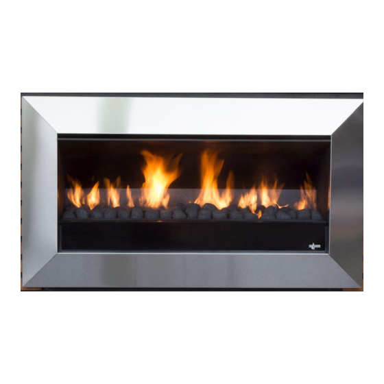
EXURO IO1000
INSTALLATION & OPERATING MANUAL
Important: The appliance shall be installed in accordance with;
·
Local gas fitting regulations
·
Municipal building codes
·
AS/NZS 5601.1:2013, Gas installations
·
Any other relevant statutory regulations.
·
TO BE INSTALLED ONLY BY AN AUTHORIZED PERSON
·
THIS APPLIANCE MUST NOT BE INSTALLED OR USED INDOORS
INSTRUCTIONS MUST BE LEFT WITH THE CONSUMER AND THE
CONSUMER TO RETAIN THEM FOR FUTURE REFERENCE.
Approval Number: GMK10105
VERSION 2
Advertisement
Table of Contents

Related Manuals for Real Flame EXURO IO1000


Summary of Contents for Real Flame EXURO IO1000
- Page 1 EXURO IO1000 INSTALLATION & OPERATING MANUAL Important: The appliance shall be installed in accordance with; · Local gas fitting regulations · Municipal building codes · AS/NZS 5601.1:2013, Gas installations · Any other relevant statutory regulations. · TO BE INSTALLED ONLY BY AN AUTHORIZED PERSON ·...
-
Page 2: Warranty Information
(www.realflame.com.au) or completing and mailing the attached registration card within 30 days of purchase of your Real Flame Gas Burner (or, if the Real Flame Gas Burner is fitted to a new home, within 30 days of the date of settlement of purchase of such new home). -
Page 3: Important Safety Notice
INSTALLATION NOTICE The installation of this appliance is only to be carried out by an authorised person in accordance with the Manufacturer’s Instructions, local gas fitting regulations, AS/NZS5601.1.2013 installation code for gas burning appliances and any other relevant statutory regulations. Do not modify this appliance. -
Page 4: Table Of Contents
Testing of the power switch and spark ignition........18 Checking Operating Pressure ..............19 Assembly of the Glass Feature...............20 Fitting the Fascia ..................20 Placement of ceramic stones ..............21 Optional Weather Cover .................21 Electrical Schematic....................22 Exploded View .......................23 Gas Conversion .....................24 Real Flame contact information ................28... -
Page 5: Data Plate
DATA PLATE (The dataplate for this appliance, containing technical information and specifications can be found to the right of the control tray, near the base of the fire. To access this, the fascia must first be removed. -
Page 6: Basic Operation
BASIC OPERATION The IO1000 is operated by the switch located on the right hand side outer edge of the fascia. The basic operations possible are ON/OFF. Before operating the fire, ensure that the power transformer is plugged into the mains wall socket and turned on, and the supply is turned on. - Page 7 BASIC OPERATION Propane ULPG Natural Gas Min. Inlet Pressure 2.5 kPa 2.5 kPa 1.00 kPa Max Inlet Pressure 5.0 kPa 5.0 kPa 5.00 kPa Manifold Pressure 2.0 kPa 2.2 kPa 1.00 kPa Front Burner Jet size Ø1.3 Ø1.25 Ø4.0 Rear Burner Jet size Ø1.3 Ø1.25 Ø4.0...
-
Page 8: Removing The Fascia
REMOVING THE FASCIA The IO1000 Stainless Steel fascia is attached to the fire by four ‘hooks’ on the corners of the fascia. If you need to remove the fascia, lift it upwards and slowly pull it away from the fire in the same motion. -
Page 9: Pilot Flame & Burner Positioning
NEVER EVER RUB THE FASCIA. The outside of a Real Flame Fascia must only be cleaned with a soft microfibre cloth. If heavier cleaning is required for the likes of grease or stubborn fingerprint removal we recommend the use of Steel Kleen brand Ezi Wipes for stainless steel fascias only, and warm soapy water for powder coated Fascias. -
Page 10: Installation
INSTALLATION WARNING Children and adults should be alerted to the hazards of high surface temperatures, burns and clothing ignition. Young Children should be carefully supervised when they are in the area of the appliance. Clothing or other flammable materials should not be hung from the appliance, or placed on or near the appliance. -
Page 11: Product Description
(continued) Product Description The Real Flame IO1000 gas fire is designed for outdoor use only. This appliance requires no flue and must be permanently installed into a cavity. It may be installed into a timber cavity. The fire is controlled by the user from a switch that is situated on the lower right hand side of the stainless steel fascia. -
Page 12: Power Supply
INSTALLATION (continued) Power Supply This appliance requires a constant external 240V AC 1A power supply to mains electricity. A plugpack transformer is supplied with the fire. Creating the Cavity The dimensioned drawing below shows the size of opening that must be created to install the unit. 1010 Where possible, it is recommended that the cavity is made slightly larger than the above dimensions to give the installer the maximum amount of space to work in. -
Page 13: Wall Cladding Around Fire
Certain materials or items, when placed under or near the appliance, will be subjected to radiant heat and could become damaged. The following installation diagrams are Real Flame IO1000 recommendations only and may or may not comply with your local council standards. Please check with your local council for actual building standards. - Page 14 INSTALLATION (continued) Types of Installation Within a partial enclosure that includes an overhead cover and no more than two walls. Within a partial enclosure that includes an overhead cover and more than two walls, the following should apply: • At least 25% of the total wall area is completely open, and •...
-
Page 15: Corner Installations
INSTALLATION (continued) Corner Installations If a cavity is to be created in a corner, the following drawings give the minimum sized interior wall dimensions possible. Note: Allowances need to be made for cladding the internal of the cavity. Dimensions of the cavity in this diagram represent the internal size only. Minimum clearance distance between adjacent wall and fascia needs to be no less than 270mm. -
Page 16: Laying Gas Pipe
INSTALLATION (continued) Laying Gas Pipe Gas pipe should be sized as per the requirements of AS5601/AG601-2000. The pipe sizing must be sufficient to deliver the following volume of gas to the heater with all other gas appliances in the home running at the same time; IO1000 Natural Gas = 49 Mj/hr IO1000 Propane = 40 Mj/hr IO1000 ULPG = 40 Mj/hr... -
Page 17: Fixing The Fire Into Cavity
INSTALLATION (continued) Fixing the fire into the cavity To fix the fire to the cavity, first drill 4 to 6 (5mm diameter) holes in the outer flange (as shaded grey in the picture below) in locations which will give you the most support from the cavity framework behind and evenly spaced around the flange. -
Page 18: Connecting The Power Supply And Power Switch
INSTALLATION (continued) Connecting the power supply and power switch The power supply socket is located below the firebox. Push the 2 pin plug/socket together with the supply from the transformer until they ‘click’. The ON/OFF power switch socket plugs into the 3 pin plug lead situated at the front RH side of the fire. -
Page 19: Checking Operating Pressure
INSTALLATION (continued) Checking Operating Pressure NOTE: Check ensure that the correct jets, for the gas being used, are installed – see page 25. This check is done at the regulator located at the lower front of the appliance. This must be done before fascia has been fitted. Pressure test point available for operating pressure (as shown below). -
Page 20: Assembly Of The Glass Feature
INSTALLATION (continued) Assembly of the Glass Feature The glass has been packaged seperately to protect it during transit, and can be found inside the firebox. Carefully insert the glass into the cartridge as shown, between the two metal flanges and push it all the way to the bottom. -
Page 21: Placement Of Ceramic Stones
Try and get an even spread across the top of the burners. Optional Weather Cover If desired, an optional Weather Cover can be purchased from your Real Flame retailer, which protects the fuelbed and burners. This should be replaced when while the fire is not in use. -
Page 22: Electrical Schematic
ELECTRICAL SCHEMATIC... -
Page 23: Exploded View
EXPLODED VIEW... -
Page 24: Gas Conversion
GAS CONVERSION Warning: Before starting the gas conversion, ensure that the fireplace is cool. Step One Remove the fascia lifting it upwards and outwards. Unplug the cable at the bottom of the fascia and then finish removing the fascia. This will give you access to remove the Burners and Stone tray. - Page 25 GAS CONVERSION (continued) Step Five Change the two jets with the conversion jets supplied in kitset. Cover the existing gas type label with the new gas type label sup-plied in kitset. Ensure serial number and date of manufacture are still visible.
- Page 26 GAS CONVERSION (continued) Propane ULPG Step Eight For Natural gas to Propane/ULPG conversion, simply remove the restrictor collars from the burners. For Propane/ULPG to Natural gas conversion you will need to re-fit the natural gas restrictor collars. These slide over the burner tube on the underside of the burners, and must be screwed into place so that the porting holes line up.
- Page 27 GAS CONVERSION (continued) Step Nine a) Insert the burners and fix them into place with the burner clamps. b) Replace the front glass feature tray and fix it back onto the firebox. c) Replace the coals, ensuring you have only one even layer. Do not heap or mound the coals.
-
Page 28: Real Flame Contact Information
REAL FLAME PTY LTD ABN 76 006 311 155 Head Office/Factory/Showroom 1340 Ferntree Gully Rd. Scoresby Vic 3179 Ph: (03) 8706 2000 Fax: (03) 8706 2001 E-mail: info@realflame.com.au Richmond - VIC Showroom 300 Swan St. Richmond Vic 3121 Ph: (03) 9428 4443 Fax: (03) 9428 4445...
Need help?
Do you have a question about the EXURO IO1000 and is the answer not in the manual?
Questions and answers