Graco ProMix 2KE Operation
Meter-based plural component proportioner
Hide thumbs
Also See for ProMix 2KE:
- Repair parts (72 pages) ,
- Operation (76 pages) ,
- Operation (60 pages)
Table of Contents
Advertisement
Operation
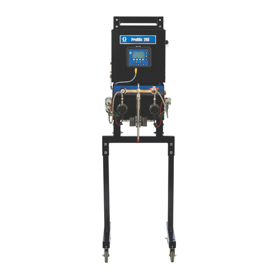
ProMix
Meter-Based Plural Component Proportioner
Self-contained, electronic plural component paint proportioner. For professional use only.
Important Safety Instructions
Read all warnings and instructions in this
manual. Save these instructions.
See page 3 for model information, including maximum
working pressure and approvals.
®
2KE
3A0869C
EN
ti15698a
Advertisement
Chapters
Table of Contents
Troubleshooting

Related Manuals for Graco ProMix 2KE


Summary of Contents for Graco ProMix 2KE
- Page 1 Operation ® ProMix 3A0869C Meter-Based Plural Component Proportioner Self-contained, electronic plural component paint proportioner. For professional use only. Important Safety Instructions Read all warnings and instructions in this manual. Save these instructions. See page 3 for model information, including maximum working pressure and approvals.
-
Page 2: Table Of Contents
Pressure Relief Procedure ....36 Graco Standard Warranty ....76 Lock Mode . -
Page 3: Models
See Special Conditions for Safe Use in Related Manuals, page 4. ProMix 2KE hazardous location equipment manufactured in the United States, with serial number beginning with A or 01, has ATEX, FM, and CE approvals, as noted. Equipment manufactured in Belgium, with serial number beginning with M or 38, has ATEX and CE approvals, as noted. -
Page 4: Related Manuals
16G353 Alternator Conversion Kit 308778 G3000 Flow Meter, Instructions/Parts 3A1324 16G351 Electric Power Conversion Kit 312781 Fluid Mix Manifold, Instructions/Parts 3A1325 ProMix 2KE Stand Kits 312782 Dosing Valve, Instructions/Parts 3A1332 24H255 3-Color Valve Stack Kit 312784 Gun Flush Box Kit 15V826 3A1333... - Page 5 Warnings WARNING ELECTRIC SHOCK HAZARD This equipment must be grounded. Improper grounding, setup, or usage of the system can cause electric shock. • Turn off and disconnect power at main switch before disconnecting any cables and before servicing equipment. • Connect only to grounded power source. •...
- Page 6 Warnings WARNING EQUIPMENT MISUSE HAZARD Misuse can cause death or serious injury. • Do not operate the unit when fatigued or under the influence of drugs or alcohol. • Do not exceed the maximum working pressure or temperature rating of the lowest rated system component.
-
Page 7: Important Two-Component Material Information
Important Two-Component Material Information Important Two-Component Material Information Isocyanate Conditions Moisture Sensitivity of Isocyanates Isocyanates (ISO) are catalysts used in two component coatings. ISO will react with moisture (such as humidity) Spraying or dispensing materials containing to form small, hard, abrasive crystals, which become isocyanates creates potentially harmful mists, vapors, suspended in the fluid. -
Page 8: Glossary Of Terms
Glossary of Terms Glossary of Terms Coriolis Meter - a non-intrusive flow meter often used in Overdose Alarm - when either the resin (A) or catalyst low flow applications or with light viscosity, shear sensi- (B) component dispenses too much material and the tive, or acid catalyzed materials. -
Page 9: Overview
Overview Overview Usage The ProMix 2KE is an electronic two-component paint • Can proportion at ratios from 0.1:1 to 30.0:1. proportioner. It can blend most two-component paints. It is not for use with quick-setting paints (those with a pot •... -
Page 10: Intrinsically Safe Installation Requirements
Installation Intrinsically Safe Installation Requirements 1. The installation must meet the requirements of the National Electric Code, NFPA 70, Article 504 Resp., Article 505, and ANSI/ISA 12.06.01. Do not substitute or modify system components as 2. Multiple earthing of components is allowed only if this may impair intrinsic safety. - Page 11 Installation Non-Hazardous Locations USER INTERFACE 10' CAN CABLE MODULE 50' OPTION USB MODULE LINE POWER POWER FILTER SUPPLY CABLE ASSEMBLY FLUID CAN CABLE CONTROL MODULE CABLE ASSEMBLY FLOW FLOW METER A METER B G3000 G3000 G3000HR G3000HR S3000 S3000 CORIOLIS CORIOLIS .
-
Page 12: Display Module
J8 on the Advanced the atomizing and turbine air to the gun. Contact your Fluid Control Module. Graco distributor for information on air shutoff valves for electrostatic applications. • Air line filter: a 10 micron or better air filter is rec-... - Page 13 1. Tighten all ProMix 2KE system air and fluid line con- nections as they may have loosened during ship- ment.
-
Page 14: Fluid Supply
Use inside the control box. the valves to shut off fluid during maintenance and service. ProMix 2KE models are available to operate air spray or Second port air-assisted systems with a capacity of up to 3800 cc/min. - Page 15 Installation DVA1 DVA2 and DVA3 (behind) ti15699a Key: Component A Meter Component B Meter DVA1 Component A Dose Valve Component B Dose Valve DVA2 Second Color/Catalyst Valve Solvent Valve B DVA3 Third Color/Catalyst Valve Meter B Check Valve Solvent Valve A Static Mixer Meter A Check Valve Fluid Integrator Assembly...
- Page 16 Installation Set Up the Fluid Manifold for Dynamic Dosing NOTE: For more information about Dynamic Dosing, see page 50. NOTE: When using dynamic dosing it is very important to maintain a constant, well-regulated fluid supply. To obtain proper pressure control and minimize pump pul- sation, install a fluid regulator on the A and B supply lines upstream of the meters.
- Page 17 Installation 11. Screw the static mixer (SM) into the injection cap (M*). Install the retained fitting (F) on the static mixer tube and secure with the nut (N1). These parts are included in the 15U955 Injection Kit. ti16335a . 8. Install 15U955 Injection Kit 12.
-
Page 18: Tubing Chart And Diagrams
Installation Tubing Chart and Diagrams Starting Ending Tube OD Type Color Description Point Point in. (mm) Green Solvent Valve A On 0.156 (4.0) Green Dose Valve A1 On 0.156 (4.0) Green Solvent Valve B On 0.156 (4.0) Green Dose Valve B On 0.156 (4.0) Green Dose Valve A2 On... - Page 19 Installation See Manual 312784 for full setup instructions for a gun flush box. B Side A Side GFB1-A ATOM-1 ti16767a A Side B Side ATOM-2 ti16768a ti16769a 3A0869C...
-
Page 20: Electrical
Neutral Ground solvent, and traffic. The ProMix 2KE operates with 85-250 VAC, 50/60 Hz ti16391a input power, with a maximum of 2 amp current draw. . 9. Control Box Electrical Connection The power supply circuit must be protected with a 15 amp maximum circuit breaker. -
Page 21: Grounding
Use grounded hoses only. to static build up or in the event of a short circuit. Spray Gun Connect the ProMix 2KE ground wire to the ground screw. Connect the clamp to a true earth ground. If wall • Non-Electrostatic: Ground the spray gun through... - Page 22 Installation Key: Control Box ground screw Control Box ground wire Gun Flush Box ground screw Gun Flush Box ground wire Power cable, Display Module/Control Box True Earth Ground - check your local code for requirements. ti16466a . 12. Grounding 3A0869C...
-
Page 23: Display Module
Display Module Display Module Screen number Error code Potlife state Active recipe LCD Display Operation mode; see Ratio page 24 for key Potlife timers Navigation keys Flow rate Enter key Soft keys Navigation Keys Error Reset Standby Key ti16319a Setup Key . -
Page 24: Icon Key
Display Module Icon Key The following tables present a printable version of the information on the ProMix 2KE icon card. See Table 5, page 54, for a printable version of the error code information on the reverse side of the card. -
Page 25: Screen Summary
Display Module Screen Summary NOTE: This summary is a one-page guide to the ProMix 2KE screens, followed by screen maps. For operating instructions, see Basic Operation, page 31. For further detail on individual screens, see Run Mode Details, page 40, or Setup Mode Details, page 42. -
Page 26: Ranges For User Inputs
Display Module Ranges for User Inputs This table is a one-sheet reference of the data range accepted for each user input. See the page indicated in the table for further screen information, if needed. Page Screen User Input Range/Options Default Run Mix Batch (3) 1 to 9999 cc 0 cc... - Page 27 Display Module . 14. Run Mode Screen Map 3A0869C...
- Page 28 Display Module . 15. Setup Mode Screen Map, page 1 3A0869C...
- Page 29 Display Module . 16. Setup Mode Screen Map, page 2 3A0869C...
- Page 30 Display Module Set Password to 9909 (See Configure Password 3, Screen 20), then enter it here. Press to exit Setup. Press reenter Setup. Setup Home (Screen 17) displays, with Troubleshooting options. System Outputs 1 Set-Up Home System Inputs Mem- Mem- brane brane Test...
-
Page 31: Basic Operation
Fluid supply containers filled 2. Graco logo will display after five seconds, followed by Run Mix Spray (Screen 2). Check all supply containers - A1 (A2 and A3, if present), B, and solvent. -
Page 32: Prime The System
Basic Operation Prime the System 9. Press . The system will purge, then load mixed material to the gun. If the gun flush box is not used, NOTE: See Run Mode Details, pages 40-41, for further trigger the gun into a grounded metal pail until the screen information, if needed. -
Page 33: Spraying
Do not press , as it will cancel the calibra- screen information, if needed. tion. 8. The volume that the ProMix 2KE measured displays on the Display Module. 1. Calibrate the meters as described in Meter Calibra- Volume measured tion, page 32. -
Page 34: Purging
Basic Operation 3. Adjust the flow rate. The fluid flow rate shown on the Purging Display Module screen is for either component A or B, depending on which dose valve is open. NOTE: See Run Mode Details, pages 40-41, for further screen information, if needed. -
Page 35: Color Change
Basic Operation 8. If the system is not completely clean, repeat step 6. Color Change Procedures 1. Place the gun in the gun flush box if used, and close NOTE: If necessary, adjust purge sequence times the lid. so only one cycle is required. 9. -
Page 36: Pressure Relief Procedure
6. Shut off the fluid supply to solvent valves A and B. NOTE: The following procedure relieves all fluid and air pressure in the ProMix 2KE system. 7. With the gun triggered, push the manual override on the A and B solvent valve solenoids to relieve sol- vent pressure. -
Page 37: Lock Mode
Change on ProMix 2KE. these inputs only if system hardware is changed. 3. Non-IS Systems: Shut off ProMix 2KE power If you change one of these inputs, the system locks so (0 position). NOTE: The system will restart in that you cannot spray or mix. -
Page 38: Use Of Optional Usb Module
Without 2. Insert USB flash drive into USB port. Use only the USB, the user can access the 50 most recent errors Graco-recommended USB flash drives; see Rec- via the Display Module. ommended USB Flash Drives, page 39. -
Page 39: Recommended Usb Flash Drives
It is recommended that users use the 4GB USB flash USB Port drive (16A004) available for purchase separately from Graco. If preferred, users may use one of the following 4 GB or less USB flash drives (not available from Graco). -
Page 40: Run Mode Details
Run Mode Details Run Mode Details Run Mix Spray (Screen 2) • Press a soft key button to select one of the main Run Mode screen sections: Mix or Errors Run Mix Spray (Screen 2) displays at startup or if is selected from Run Home (Screen 1). -
Page 41: Run Mix Totals (Screen 4)
Run Mode Details Run Mix Totals (Screen 4) Run Log Errors (Screens 5-14) Run Mix Totals (Screen 4) displays if is selected Run Log Errors (Screens 5-14) display if from Run Mix Batch (Screen 3). Use this screen to view selected from Run Home (Screen 1). -
Page 42: Setup Mode Details
Setup Mode Details Setup Mode Details Press on any screen to enter the Setup screens. If the system has a password lock, Password (Screen 16) Software Version: displays. If the system is not locked (password is set to Display Module 0000), Setup Home (Screen 17) displays. - Page 43 Setup Mode Details System Gun 1 hose Gun flush Gun 2 length type hose length Number Gun 1 hose of guns Dosing Gun 2 hose diameter type Number diameter of colors Home Home . 37. Configure 2 (Screen 19) . 35. Configure 1 (Screen 18) Configure 3 (Screen 20) allows users to set preferred language (for optional USB Module), date format, date, •...
-
Page 44: Recipe 0 (Screen 27)
Setup Mode Details Recipe 0 (Screen 27) Recipe 1-2 (Screen 29) The Recipe Screens allow the user to set up the basic Note about Settings of 0: If a Flush time is set to 0, that valve will not flush. recipes. -
Page 45: Maintenance 1-3 (Screens 24-26)
Setup Mode Details Maintenance 1-3 (Screens 24-26) Maintenance Recommendations The following table shows recommended starting values Maintenance 1 (Screen 24) displays if is selected for maintenance. Maintenance needs will vary based on on Setup Home (Screen 17). The Maintenance Screens individual applications and material differences. -
Page 46: Calibration 1 And 2 (Screens 22 And 23)
Setup Mode Details Calibration 1 and 2 (Screens 22 • Press to highlight the meter you wish to cali- and 23) brate. Press . An X displays in the box. NOTE: See Meter Calibration, page 32, for detailed • Press to start the calibration on the checked instructions. - Page 47 Setup Mode Details Troubleshooting System Inputs (Screen 35) Troubleshooting System Outputs (Screen 37) From Setup Home (Screen 17) with Troubleshooting From Setup Home (Screen 17) with Troubleshooting active, press to display Troubleshooting System Inputs (Screen 35). An X displays in the box to indicate if active, press to display Troubleshooting System Air Flow Switch 1 or 2 is on and if the gun is in the Gun...
-
Page 48: Dosing Options
ProMix 2KE controller. The controller monitors these pulses and signals. 7. When the gun is triggered again, the ProMix 2KE continues the process where it left off. c. When the target volume dispenses, Dose Valve A closes. - Page 49 Dosing Options DVA1 DVA2 and DVA3 (behind) ti15699a Key: Component A Meter Component B Meter DVA1 Component A Dose Valve Component B Dose Valve DVA2 Second Color/Catalyst Valve Solvent Valve B DVA3 Third Color/Catalyst Valve Static Mixer Solvent Valve A Fluid Integrator .
-
Page 50: Dynamic Dosing
Dosing Options Dynamic Dosing Overview Select Dynamic Dosing Dynamic Dosing provides on-demand proportioning, 1. On the Display Module press to access Setup eliminating the need for an integrator and therefore min- imizing undesired material contact. This feature is espe- Home (Screen 17). Select to display Configure cially useful with shear-sensitive and waterborne 1 (Screen 18). - Page 51 Dosing Options B Pressure B Pressure Too Low Too Low B Pressure Too High B Pressure Too High A Pressure B Pressure A Pressure B Pressure . 50. A/B Control Range with Properly Sized Restrictor NOTE: If the restrictor is too small, it may be necessary to supply more differential pressure than is available in your system.
-
Page 52: System Errors
Air or Air-assisted Guns The air flow switch (AFS) detects air flow to the gun and signals the ProMix 2KE controller when the gun is trig- gered. The AFS functions with the flow meters to ensure that system components are functioning correctly. -
Page 53: System Idle Notice (Idle)
System Idle every 2 minutes when in Mix mode. System Idle Notice (IDLE) This warning occurs if the ProMix 2KE is set to Mix and 2 minutes have elapsed since the system received a flow meter pulse. -
Page 54: Error Codes
System Errors Error Codes Table 5: System Alarm/Advisory/Record Codes Table 5: System Alarm/Advisory/Record Codes Code Description Details Code Description Details MEB1 Mix valve B maintenance due Alarm Codes - Alarm sounds, system stops, icon dis- plays until problem is solved and alarm is cleared. MESA Solvent valve A maintenance due Communication Error... -
Page 55: Alarm Troubleshooting
System Errors Alarm Troubleshooting Alarm and Description Cause Solution The CAN cable between the Display Mod- Verify that the cable is correctly con- Communication Error ule and the Advanced Fluid Control Mod- nected. The Display Module is not ule is not connected. communicating with the The CAN cable is cut or bent. -
Page 56: Premix Error - Color
System Errors Alarm and Description Cause Solution SFA1, SFA2, SFA3 or SFB1 Check components and clean, repair, or Gun, line, valve, or meter is plugged or PreMix Error replace as necessary. stuck. In systems with a gun flush Check and repair pump. See pump Feeder pump or solvent pump is not box, insufficient quantity of manual for repair procedures and... -
Page 57: R1 Ratio Low Error
Slow actuation of the component A or B Manually operate the Dose Valve A1 valves. This can be caused by: (A2, A3) and B solenoid valves as instructed in the ProMix 2KE Repair-Parts manual to check opera- tion. • Air pressure to the valve actuators is •... -
Page 58: R4 Ratio High Error
System Errors Alarm and Description Cause Solution There is too little restriction in the system. • Check that the system is fully Ratio High Error loaded with material. The mix ratio is higher than • Check that the supply pump’s cycle the set tolerance for an A to B rate is set properly. -
Page 59: Qda1 Qda2 Qda3
(such as QDB1 fans and conveyors). Overdose B 3. Check if the ProMix 2KE is reading The B dose has overshot, forc- any fluid flow. ing an A dose that, when com- bined with B, is too large for 4. -
Page 60: Qta1 Qta2 Qta3
System Errors Alarm and Description Cause Solution QTA1, QTA2, QTA3, or QTB1 System is in Mix mode and gun is only Fully trigger the gun. Dose Time Error partially triggered, allowing air but no fluid The gun trigger is active, but to pass through gun. -
Page 61: Dynamic Dosing Restrictor Selection Graphs
Dynamic Dosing Restrictor Selection Graphs Dynamic Dosing Restrictor Selection Graphs Use the graphs on pages 62- 66 as a guide to determine the correct restrictor size for your desired flow and mate- Table 6: Restrictor Sizes rial viscosity. Table 6 lists the available restrictor sizes. Size Code Orifice Size Part No. - Page 62 Dynamic Dosing Restrictor Selection Graphs (bar, MPa) 4000 (276, 27.6) 3500 (241, 24.1) #2 Restrictor #3 Restrictor 3000 #4 Restrictor (207, 20.7) #7 Restrictor 2500 (172, 17.2) 2000 (138, 13.8) 1500 (103, 10.3) 1000 (69, 6.9) (34, 3.4) 1000 1500 2000 2500 3000...
- Page 63 Dynamic Dosing Restrictor Selection Graphs (bar, MPa) 1400 (97, 9.7) 1200 (83, 8.3) #2 Restrictor #3 Restrictor 1000 #4 Restrictor (69, 6.9) #7 Restrictor (55, 5.5) (41, 4.1) (28, 2.8) 14, 1.4) 1000 1500 2000 2500 3000 3500 4000 Flow Rate (cc/min) Detail View (28, 2.8) (21, 2.1)
- Page 64 Dynamic Dosing Restrictor Selection Graphs (bar, MPa) (55, 5.5) #2 Restrictor (48, 4.8) #3 Restrictor #4 Restrictor #7 Restrictor (41, 4.1) (34, 3.4) (28, 2.8) (21, 2.1) (14, 1.4) (7, 0.7) 1000 1500 2000 2500 3000 3500 4000 Flow Rate (cc/min) Detail View (14, 1.4) (10, 1.0)
- Page 65 Dynamic Dosing Restrictor Selection Graphs (bar, MPa) (21, 2.1) (17.2, 1.72) #2 Restrictor #3 Restrictor #4 Restrictor #7 Restrictor (14, 1.4) 10.3, 1.03) (7.0, 0.7) (3.4, 0.34) 1000 1500 2000 2500 3000 3500 4000 Flow Rate (cc/min) Detail View (7, 0.7) (5.2, 0.52) (3.4, 0.34) (1.7, 0.17)
- Page 66 Dynamic Dosing Restrictor Selection Graphs (bar, MPa) (14, 1.4 (12.4, 1.2 #2 Restrictor #3 Restrictor (11, 1.1) #4 Restrictor #7 Restrictor 9.7, 0.9) 8.3, 0.8) (7, 0.7) (5.5, 0.55) (4.1, 0.41) (2.8, 0.28) (1.4, 0.14) 1000 1500 2000 2500 3000 3500 4000 Flow Rate (cc/min)
- Page 67 Dynamic Dosing Restrictor Selection Graphs 3A0869C...
-
Page 68: Schematics
Schematics Schematics Hazardous Location System Pneumatic Schematic 3A0869C... - Page 69 Schematics Non-Hazardous Location Pneumatic Schematic 3A0869C...
- Page 70 Schematics Hazardous Location Electrical Schematic CAN_L +V_CAN V_CAN_RTN CAN_H SHIELD UNUSED ALTERNATOR 18 PSI CAN_L CAN_L UNUSED +V_CAN +V_CAN MODULE 1.5 FCM UNUSED V_CAN_RTN V_CAN_RTN UNUSED (MIN) CAN_H CAN_H UNUSED SHIELD SHIELD V CAN CAN_L USB COMPONENT USB BASE V CAN +V_CAN MODULE GRND...
- Page 71 Schematics Hazardous Location Electrical Schematic (continued) UNUSED CAN_L UNUSED +V_CAN UNUSED V_CAN_RTN UNUSED CAN_H UNUSED SHIELD FLUID CONTROL UNUSED UNUSED MODULE AFS #1 (+) ALARM (+) COMMON COMMON PURGE A (+) PURGE B (+) DOSE B (+) DOSE A1 (+) +12 VDC +12 VDC FLOW METER B SIG...
- Page 72 Schematics Non-Hazardous Location Electrical Schematic CAN_L TERMINAL +V_CAN BLOCK V_CAN_RTN CAN_H GRND SHIELD POWER SUPPLY GRND LINE POWER FILTER CAN_L CAN_L +V_CAN +V_CAN V_CAN_RTN V_CAN_RTN CAN_H CAN_H SWITCH SHIELD SHIELD ROCKER V CAN USB COMPONENT USB BASE V CAN MODULE V CAN MODULE V CAN RTN...
- Page 73 Schematics Non-Hazardous Location Electrical Schematic (continued) CAN_L CAN_L +V_CAN +V_CAN FLUID V_CAN_RTN V_CAN_RTN CAN_H CAN_H CONTROL SHIELD SHIELD MODULE UNUSED UNUSED ALARM (+) AFS #1 (+) COMMON COMMON PURGE A (+) PURGE B (+) DOSE A1 (+) DOSE B (+) +12 VDC +12 VDC FLOW METER B SIG...
-
Page 74: Dimensions And Mounting
Dimensions and Mounting Dimensions and Mounting 14.74 in. 1.0 in (37 cm) (2.5 cm) 0.55 in 12.74 in. (1.4 cm) (32 cm) Depth: 14.8 in. (38 cm) 36.1 in. (92 cm) 35.5 in. (90 cm) 33.5 in. (85 cm) 20.1 in. (51 cm) 3A0869C... -
Page 75: Technical Data
Air filter inlet size ......3/8 npt(f) Air filtration for air logic (Graco-supplied)... .‘ 5 micron (minimum) filtration required; clean and dry air Air filtration for atomizing air (user-supplied) 30 micron (minimum) filtration required;... -
Page 76: Graco Standard Warranty
With the exception of any special, extended, or limited warranty published by Graco, Graco will, for a period of twelve months from the date of sale, repair or replace any part of the equipment determined by Graco to be defective.
Need help?
Do you have a question about the ProMix 2KE and is the answer not in the manual?
Questions and answers
What causes a ske to go into idle as it's spraying
The Graco ProMix 2KE goes into System Idle while in Mix mode if no flow meter pulse is received for 2 minutes. This typically happens when there is no gun trigger or no air flow switch (AFS) input.
This answer is automatically generated