Table of Contents
Advertisement
Quick Links
Instructions
®
GL-32
®
GL-43
For Single-Line, Parallel, and Automatic Injector Systems Dispensing Grease, N.L.G.I.
grades #000 - #2 and Oil (minimum SAE 10 weight)
Model Nos.:
GL-32
1/4 NPT
CS
Outlet
3.2 mm
Stand-Alone
24A919
Replacement
24A920
1X Manifold
24A921
2X Manifold
24A922
3X Manifold
24A923
4X Manifold
24A924
3500 psi (24 MPa, 241 bar) Maximum Working Pressure - Grease Models
1000 psi (6.89 MPa, 68.9 bar) Maximum Working Pressure - Oil Models
Important Safety Instructions
Read all warnings and instructions in this
manual. Save these instructions.
(Grease) and
(Oil) Injectors
GL-32
GL-32 SST
1/8 BSPP
1/4 NPT
CS
SST
6 mm
3.2 mm
NA
24E389
24F508
24E390
24F509
24E391
24F510
24E392
24F511
24E393
24F512
24E394
.
GL-32 SST
GL-43
1/8 BSPP
1/4 NPT
SST
CS
6 mm
3.2 mm
NA
24E240
24F550
24E245
24F551
24E241
24F552
24E242
24F553
24E243
24F554
24E244
313798S
GL-43
GL-32
1/8 BSPP
1/4 NPT
CS
CS
6 mm
6 mm
NA
NA
24F543
26C065
24F544
NA
24F545
24Z542
24F546
NA
24F548
24Z544
EN
GL-32
1/4 NPT
CS
3.2 mm
NA
24W508
NA
NA
24W916
24W917
Advertisement
Table of Contents

Related Manuals for Graco GL-32


Summary of Contents for Graco GL-32
- Page 1 GL-43 (Oil) Injectors 313798S For Single-Line, Parallel, and Automatic Injector Systems Dispensing Grease, N.L.G.I. grades #000 - #2 and Oil (minimum SAE 10 weight) Model Nos.: GL-32 GL-32 GL-32 SST GL-32 SST GL-43 GL-43 GL-32 GL-32 1/4 NPT 1/8 BSPP...
- Page 2 Warnings Adjustment Instructions Reference numbers refer to parts (F . 1 and page 4). 1. Loosen lock nut (7). 2. Hand tighten the Adjuster Nut (8) then loosen, SKIN INJECTION HAZARD approximately 1/2 turn to achieve the minimum dis- High-pressure fluid from dispense valve, hose leaks, or rup- pensed output volume (.001 in.
- Page 3 Operation Operation Stage 1 Stage 2 Pressurized fluid moves the injector piston forward and After fluid is discharged, the pressure is relieved and the forces fluid through the outlet check valve to the feed injector piston returns to the rest position. Lubricant in line.
- Page 4 Operation Parts Ref. Part No. Description 15W661 BLOCK, manifold, 1 injector , 1/4 NPT (model 24A921, 24E241) 16M401 BLOCK, manifold, SST, 1 injector, 1/4 NPT (model 24E391) 15W662 BLOCK, manifold, 2 injectors, 1/4 NPT (model 24A922, 24E242, 24Z542) 16M402 BLOCK, manifold, SST, 2 injectors, 1/4 NPT (model 24E392) 7 17 15W663...
- Page 5 Technical Data Ref. Part No. Description 15 SPACER, manifold inlet 15W658 CLIP, manifold (all non-SST models only, 24A921-24A924, 24F509-24F512; 24E241-24E244; 24Z542, 24Z544, 24F544, 24F545, 24F546, 24F548. 24W916, 24W917) 124619 CLIP, SST, manifold (models, 24E391-24E394; 24F551-24F554) 123962 SEAL, square, GL-Series ‡ 131252 SEAL, square, GL-Series (for low tem- perature applications)
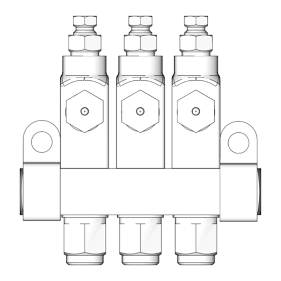
- Page 6 Technical Data Dimensions Model 24A923 Shown F (OD tubing dispense outlet) ti13949 NPT or F† Injector BSPP in. / mm in./mm in./mm in./mm in./mm in./mm in./mm in./mm in./mm in./mm Stand single manifold alone injector 3.12/ 0.68/ 79.4 17.3 Manifold replacement for manifold 1.14/ 1.75/...
- Page 7 Notes Notes 313798S...
- Page 8 With the exception of any special, extended, or limited warranty published by Graco, Graco will, for a period of twelve months from the date of sale, repair or replace any part of the equipment determined by Graco to be defective.
Need help?
Do you have a question about the GL-32 and is the answer not in the manual?
Questions and answers