Table of Contents
Advertisement
Quick Links
Package checklist
The package includes the following items:
One GW-7228 hardware module
One Quick Start
One software utility CD
One screw driver
One RS-232 cable (CA-0910)
Note:
If any of these items are missed or damaged, contact the
local distributors for more information. Save the shipping
materials and cartons in case you want to ship in the future.
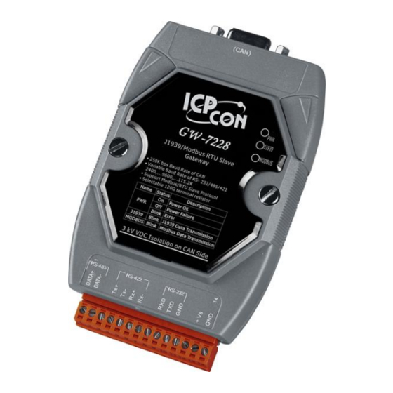
Appearance and pin assignments
CAN DB9 Male Connector
Pin
1
2
3
4
5
6
7
8
9
Description
Not Connect
CAN Low
CAN Ground
Not Connect
CAN Ground
CAN High
Not Connect
GW-7228 Quick Start v1.2 2011/05
14-pin screw terminal connecter
Pin
Description
1
RS-485 DATA+
2
RS-485 DATA-
3
Not Connect
4
RS-422 Tx+
5
RS-422 Tx-
6
RS-422 Rx+
7
RS-422 Rx-
8
Not Connect
9
RS-232 RXD
10
RS-232 TXD
11
RS-232 GND
12
Not Connect
13
+Vs(+10 ~ +30 VDC)
14
Quick Start
May 2011 Version 1.2
GND
1 1 1 1 / / / / 8 8 8 8
Advertisement
Table of Contents

Related Manuals for ICP DAS USA GW-7228


Summary of Contents for ICP DAS USA GW-7228
-
Page 1: Quick Start
GW-7228 Quick Start v1.2 2011/05 Quick Start May 2011 Version 1.2 Package checklist The package includes the following items: One GW-7228 hardware module One Quick Start One software utility CD One screw driver One RS-232 cable (CA-0910) Note: If any of these items are missed or damaged, contact the local distributors for more information. -
Page 2: Led Indication
Blink Bus Idle Installation If users want to start the GW-7228 normally, it needs to follow these steps to install the GW-7228 below: Step1: Check GW-7228 Firmware Mode Users need to set the dip-switch to the “Normal” position as Figure 2 and reset... - Page 3 Figure 2: Operation mode Position of Dip-Switch Step2: J1939 network - CAN bus connection Connect the CAN ports with the GW-7228 modules and ECU (e.g. engine) in J1939 network using the following structure as Figure 3. Figure 3: CAN bus Wire Connection...
- Page 4 Figure 5: Power Wire Connection GW-7228 Utility Configuration Modbus Network Configuration The GW-7228 and the controller must be set the same serial communication parameters of the Modbus network configuration. The Modbus network configuration screen from GW-7228 is shown as Figure 6.
- Page 5 Controller, we want to receive the Transmission Output Shaft Speed from the transmission and send the Transmission Input Shaft Speed to the transmission via the GW-7228. The following table shows the current planning. Figure 8: Example of a parameter group definition of SAE J1939/71...
- Page 6 GW-7228 Quick Start v1.2 2011/05 ECU’s J1939 Address Byte Order Priority Byte Data Transm- ECU’s In J1939 Order In Length ission (DEC) J1939 Data Field Modbus Repetiti- Address Figure 9: J1939 configuration screen Upload Parameter to the GW-7228 After the previous parameter settings, users need to upload the parameters to the GW-7228.
- Page 7 Read a value of one word in the address 30001. [Request] (Byte0, Byte1... Byten) (Hex) 01 04 00 00 00 01 31 CA(CRC) GW-7228 responds a value of one word in the address 30001. [Response](Byte0, Byte1... Byten) (Hex) 01 04 02 12 34...
-
Page 8: Troubleshooting
Step3 after 500 ms later. 4. Reset the power of the GW-7228, and the GW- 7228 would back to factory defaults. Step4 5. Reconnect the GW-7228 by using the network setting as 115200 baud with none parity, 1 stop bit and 1 Net ID.
Need help?
Do you have a question about the GW-7228 and is the answer not in the manual?
Questions and answers