Table of Contents
Advertisement
Quick Links
Advertisement
Table of Contents

Related Manuals for ICP DAS USA GW-7472


Summary of Contents for ICP DAS USA GW-7472
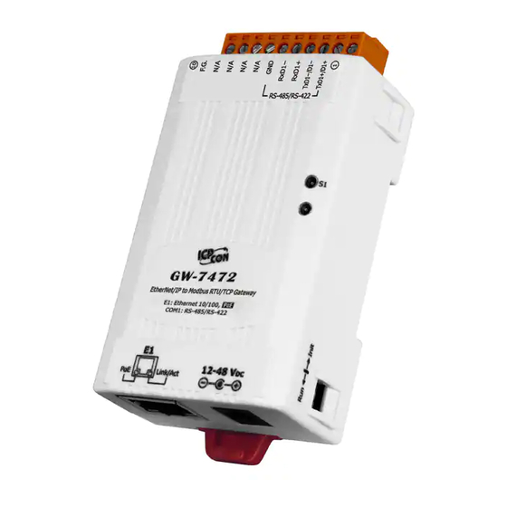
- Page 1 ICP DAS GW-7472 FAQ FAQ Version 3.1 ICP DAS Co., Ltd. 2014-10-13...
-
Page 2: Table Of Contents
Table of Contents Q1: Could you please confirm that GW-7472 works with SLC-500 (SLC5/05) without any problems? ....3 Q2: In some case, the byte order of the AI/AO word data in the communication is reversed, i.e. low byte is MSB and high byte is LSB. -
Page 3: Q1: Could You Please Confirm That Gw-7472 Works With Slc-500 (Slc5/05) Without Any Problems
Q1: Could you please confirm that GW-7472 works with SLC-500 (SLC5/05) without any problems? A1: We never test GW-7472 this device with SLC-500. But this device ever tested with the Hilscher CIFX 50-RE Ethernet/IP master. It can communicate with the master via following I/O connection methods. -
Page 4: Q3:How To Make A Class1 Connection With The Gw-7472 Utility Diagnostic Window
Q3:How to make a Class1 connection with the GW-7472 Utility Diagnostic window? A3:Configure the total output/input size in the “Forward Open Class1 Behavior” on the Diagnostic window. Please notice that the total input/output size on the Diagnostic window and the total input/output size on the Configuration window must be the same. -
Page 5: Q4:Why Did The Pop-Up Message "Fw Version Error" Be Shown After I Run The New Version Utility
Q4:Why did the pop-up message “FW Version Error” be shown after I run the new version Utility? A4:The utility of version 2.0 and later only supports the firmware version 2.0 and the after. Please go to the product page of the GW-7472 to get the new firmware and update the module. The firmware... - Page 6 Please follow our steps to update the firmware : Step1:We provide two ways to check MAC address. (a) Use v1.X GW-7472 Utility configuration window to find out your MAC address on the top of “Network Settings”. (b)In another way, you can get your MAC address from the ARP list. Follow the “[Start Menu] [Run] ...
- Page 7 Step2:Follow these steps “[Main Menu][Device][Download]” to open the FW download window. Key in the MAC address we found in Step1, and an available IP address on this window. Select the firmware file (e.g. GW7472_v2.dat) to download. Step3:After downloading the firmware, please check the Utility whether the version is V2.0 or not on the Main Menu.
-
Page 8: Q5:How To Connect To The Allen-Bradley Plc
(b)Configure the “Module Properties” window. Please notice that the total input size on the Module Properties window and the total input size on the GW-7472 Utility must be the same. Also, the total output size on the Module Properties window and the total output size on the GW-7472 Utility must be... -
Page 10: Q6:How To Check The Connections Between The Gw-7472 And The Modbus Devices
Q6:How to check the connections between the GW-7472 and the Modbus devices? A6:Open the GW-7472 Utility Diagnostic window, and set the UCMM values (Service = E, Class Code = 4, Instance ID = 67, Attribute ID = 3), as shown in the figure below. Click “Class3” to start the connection. -
Page 11: Q7: How Can I Check The Wire Connections
Q7: How can I check the wire connections? A7:There are 4-wire RS-422 wiring and 2-wire RS-485 wiring. The wire connection interface is shown below. RS-485 RS-422 The wire connections between Modbus masters and Modbus slaves must be follow the figure we show below. -
Page 12: Q8:How To Set Up The Gw-7472 For Modbus Tcp
Q8:How to set up the GW-7472 for Modbus TCP? A8:In the GW-7472 configuration window, please change the “Device Options” to be “TCP No.0” in the “Modbus Request Command” and fill out the Modbus device settings you want to connect with. -
Page 13: Q9:How To Set Up Gw-7472 In Rslogix 5000 Msg Ladder Element
Q9:How to set up GW-7472 in RSLogix 5000 MSG ladder element? A9: If you want to connect to GW-7472 with Get Attribute Single or Set Attribute Single, you can configure MSG ladder element in your routine. Please refer the steps to complete the configurations. - Page 14 (2) Add a new routine. (3) Add MSG element in your ladder and select “input_tags”.
- Page 15 Ethernet module in the PLC, add a comma, a space, and a 2, this indicates that the message should be routed out on Ethernet. Following the 2 add a comma, a space, and the IP-address to GW-7472, here 192.168.22.72. This is everything that has to be done here, click on OK.
- Page 16 (4) Add MSG element in your ladder and select “Output_tags”.
- Page 17 Configure the Message Configuration. here we have to select the “Service Type” of “Set Attribute Single”. To fill in the “Class” as 4, “Instance” as 102 and “Attribute” 3. For “Source Element” select the “output_data” tag and the “Source Length” should be 4 bytes. Under “Communication”...
- Page 18 If you want to send Get/Set Attribute Single continuously, you can refer to the ladder below.
Need help?
Do you have a question about the GW-7472 and is the answer not in the manual?
Questions and answers