Advertisement
Advertisement
Table of Contents

Subscribe to Our Youtube Channel
Related Manuals for PowerTech PW320


Summary of Contents for PowerTech PW320
- Page 1 PW320/PW330 USER MANUAL SWING GATE OPENERS 24V DC GEAR MOTOR FOR RESIDENTIAL Flashing Light Push Button Control box Gate 2 Gate 1...
-
Page 2: Declaration Of Conformity
Manufacturer: Timotion Technology Co., Ltd. Address: Shiyong Minying Industrial Zone, Hengli Town, DongGuan City, GuangDong, China Model: PW320; PW330; PR-1 1. Certificate of conformity of a product with the essential requirements art. 3.2 of the R&TTE Directive 1999/5/EC. 2. The above product has been tested with the listed standards and in compliance with the European Directive LVD 2006/95/EC. -
Page 3: Table Of Contents
Product Description and Applications PW330 Applications PH-2 Photocells Description of The Automation PKS-1 Key Selector Description of Devices PPB-1 Push Button 1.3.1 PW320/PW330 Electromechanical PF-1 Flashing Light Gear Motors PR-1 Transmitter 1.3.2 PC170 Control Box PEL-1 Electric Latch 1.3.3 PH-2 Photocells 1.3.4... -
Page 4: Warnings 2
If there is a failure that cannot be solved and is not mentioned in this manual, please contact qualified Keep all the components of PW320/230 system and this installation personnel. manual for further consultation. Do not use the gate-automated system before all the... - Page 5 1) Product Description and Applications 1.1 Applications PW320/PW330 is applied for residential automation of single or dual leaf gate. PW320/PW330 has to be operated with electricity and it’s forbidden to be operated by back-up batteries for normal use. Back-up batteries are only allowed for emergent operation when there is a power failure, and the gear motors can be released by special keys to move the gate manually.
-
Page 6: Control Box
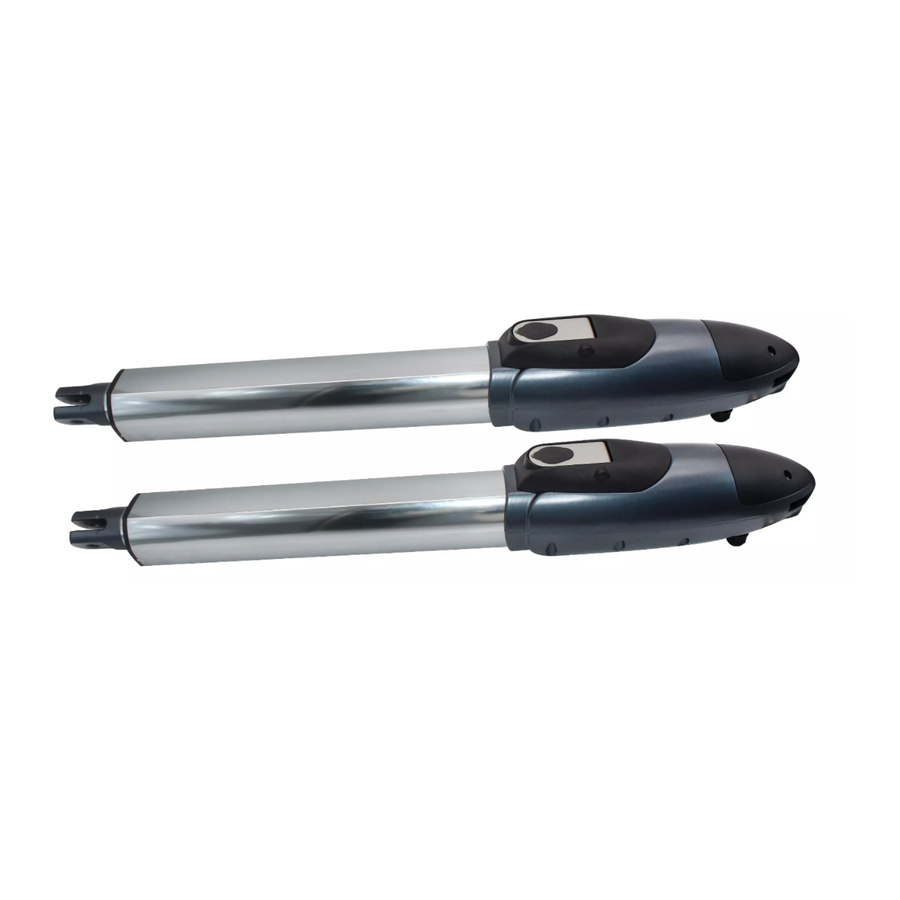
1.3.1 PW320/PW330 Electromechanical Gear Motors Figure 3 PW320/PW330 consists of a worm screw reduction 1)PW320 gear and a 24V direct current motor. The gear motor could be released manually by special release keys when there is a power failure. The gear motor is installed with two post brackets, one rear plate and one front plate for the installation. -
Page 7: Ppb-1 Push Button
2.1 Notes of Motors in Operation The PW320/PW330 gate openers are applicable to per leaf of 3.0/4.0 meters in width and 250/350 kg in weight which can be opened up to 120 degrees primarily for residential use; where the performance shall be influenced by the factors such as gate dimension, weight and climate that the driven torque is necessarily to be adjusted properly. -
Page 8: Tools In Installing
Figure 12 2.2 Power Connection PW320/PW330 is required to connect two cores wires, which requires very low voltage that no professionally trained personnel is required in installation; however, the users are advised to read the installation manual carefully before going for it. After getting to know all accessories and their positions, suggest starting from cable conduit arrangement to prevent the cables from being broken or damaged 2.2.1 Notes for Power Connection... -
Page 9: Installation
2.3 Installation 2.3.1 Preparation for Motor Installation PW320/PW330 is not applicable to a gate which is inefficient or unsafe, neither to solve the defects due to incorrect installation nor poor maintenance. Check the following items before going for installation: 1). Make sure the weight and dimensions of the gate conform to the operation range of PW320/PW330. Don’t use PW320/PW330 if the gate specifications do not meet the requirements. - Page 10 100 degrees, then the value of “B” is approximate 190mm. **Please make sure “B” and “A” are similar or the same in value that the leaves can be operated smoothly, also to reduce the burden of the motor. INSTRUCTIONS PW320/PW330...
-
Page 11: Installation Of The Gear Motors
Figure 22 Figure 21 PW330 PW320 10. Refer to Figure 23, the distance between front plate of the motor and rear plate is 735mm (PW320) / 798mm (PW330), the difference in height is 18.3mm (PW320) / 22.5mm (PW330). PW330 PW320... - Page 12 1) Turn the round plate on the release part to “OPEN” position. See Figure 29. 2) Push out the release part to the end. See Figure 30. 3) Use the release key to turn the pin anti-clockwise to the end. See Figure 31. Figure 29 Figure 30 Figure 31 INSTRUCTIONS PW320/PW330...
-
Page 13: Pks-1 Key Selector
8). Turn the key and insert the shell on the bottom. Turn the key back to the center position and the shell will be fixed to the bottom. 9). Tighten the lock body with the two screws and insert the round cover by pressing it to attach to the whole unit. Figure 2.3.3 (5) Figure 2.3.3 (6) INSTRUCTIONS PW320/PW330... -
Page 14: Ppb-1 Push Button
3.) Connect the wires and penetrate the wires into the hole of the base. See Figure 2.3.5 (3). 4.) Drill the holes in the wall and fix the bottom to the wall by three screws. See Figure 2.3.5 (4). Figure 2.3.5 (1) Figure 2.3.5 (2) Figure 2.3.5 (3) Figure 2.3.5 (4) INSTRUCTIONS PW320/PW330... -
Page 15: Ph-2 Photocells
4). Power-up the photocells and make sure the LED light on receiver and transmitter are ON. Figure 2.3.6 (1) Figure 2.3.6 (2) Lens Beam Alignmnet N.C. Indicator N.O. Power Led Indicator DC (12~24V) Terminal Block Power Terminal Block DC (12~24V) Figure 2.3.6 (3) INSTRUCTIONS PW320/PW330... -
Page 16: Pel-1 Electric Latch And Ps-1 Stopper
See Figure 2.3.7 (4), Figure 2.3.7 (5), Figure 2.3.7 (6) & Figure 2.3.7 (7) Figure2.3.7(6) Figure2.3.7(4) Unscrew the screws. Figure2.3.7(5) Take the casing off. The location of the spring. (Installation) Figure2.3.7(7) Change the spring and screw it in the different place. INSTRUCTIONS PW320/PW330... - Page 17 3). The gap between the bottom of electric latch and the stopper should be less than 7mm. See Figure 2.3.7 (10) Figure2.3.7(10) For the gate opened inward. Figure2.3.7(11) For the gate opened Outward. 4). Connect the wires of the electric latch to the terminal LAT(+) and LAT(-) on the PCB. INSTRUCTIONS PW320/PW330...
-
Page 18: Technical Characteristics
3) Technical Characteristics 3.1/3.2 PW320 / PW330 PW320 PW330 Motor 24Vdc motor with mechanical release 24Vdc motor with mechanical release Gear type Worm gear Worm gear Max Absorbed Power 144W 144W Peak thrust 3000N 3500N Nominal thrust 2500N 3000N Stroke length... -
Page 19: Pf-1 Flashing Light
Operating Temperature -20℃~+50℃ Installation horizontally or vertically installed Dimension 205mm * 80mm * 75mm 3.7 PR-1 Radio Transmitter Application Radio transmitter for remote control of PW320/PW330 Frequency 433.92Mhz Coding Rolling code Buttons 2, for single-gate or dual-gate operation Power Supply...
Need help?
Do you have a question about the PW320 and is the answer not in the manual?
Questions and answers