
Subscribe to Our Youtube Channel
Related Manuals for PowerTech PL300E


Summary of Contents for PowerTech PL300E
- Page 1 PL300E / PL400E / PL500E / PL800E SLIDING GATE OPENERS 24V DC MOTOR FOR RESIDENTIAL USER MANUAL...
- Page 2 Declaration of Conformity Model: PL300E, PL400E, PL500E, PL800E, PR-1 1. Certificate of conformity of a product with the essential requirements art. 3.2 of the R&TTE Directive 1999/5/EC. 2. The above product has been tested with the listed standards and in compliance with the European Directive LVD 2006/95/EC.
-
Page 3: Table Of Contents
4.5 PRB-1 External Receiver Box Data Sheet P.11 5. Additional Information P.12 5.1 Wire Connection of PH-1 Photocell (Safety Beam) P.12 5.2 Wire Connection and Setting Of PRB-1 External Reciever Box P.13 5.3 Green Box Installation Guide P.14 INSTRUCTIONS PL300E/PL400E/PL500E/PL800E SLIDING GATE OPENER USER MANUAL... -
Page 4: Warnings
– when operating a biased-off switch, make sure that other persons are Keep all the components of PL300E / PL400E / PL500E / PL800E system kept away; and this manual for further consultation. -
Page 5: Installation
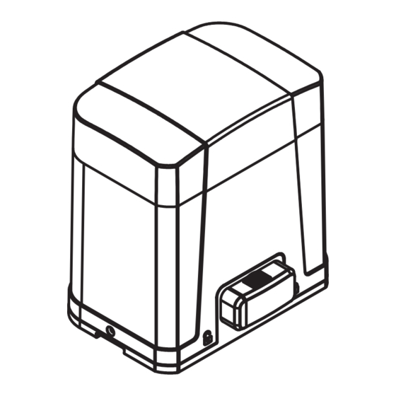
4. Flashing light 2.2 Description of Device a. Operation gear e. Release device b. Limit switch device f. Control panel c. 24Vdc motor g. Terminals of devices d. Back-up batteries (Optional) h. Green Box (Optional) INSTRUCTIONS PL300E/PL400E/PL500E/PL800E SLIDING GATE OPENER USER MANUAL... -
Page 6: Dimension Of Device
2.3 Dimension of Device 2.4 Installation of Motor Gear and Gear Rack INSTRUCTIONS PL300E/PL400E/PL500E/PL800E SLIDING GATE OPENER USER MANUAL... -
Page 7: Checking For Installation
Step2. Insert the key and turn counterclockwise to unlock the device. Step3. Turn counter-clockwise of the bar to release the motor To restore the automation, simply reverse the above procedure. Step1. Step2. Step3. INSTRUCTIONS PL300E/PL400E/PL500E/PL800E SLIDING GATE OPENER USER MANUAL... -
Page 8: Setup And Function Setting
If the LED display is in normal performing refer to “4.2.1”, you can control the gate by either transmitters or the button on the board: “UP”-clockwise moving, “SET”- stop and “DOWN”- Counterclockwise moving. PF-1 PF-1 PPB-1 PKS-1 PPB-1, PKS-1: LED2 LED1 Green Box Antenna INSTRUCTIONS PL300E/PL400E/PL500E/PL800E SLIDING GATE OPENER USER MANUAL... -
Page 9: System Learning, Reset Process And Led Display
If this reading increase instantly or stay in high reading, please check if any object in between of the gate moving area, and contact your installer for inspection. INSTRUCTIONS PL300E/PL400E/PL500E/PL800E SLIDING GATE OPENER USER MANUAL... -
Page 10: Programmable Function Settings
1. The factory setting is “6-4” Deceleration Speed (% full speed) 1. The function can adjust the running force of motor to be compatible with the gate weight. Over current setting 2. The factory setting is "7-5". INSTRUCTIONS PL300E/PL400E/PL500E/PL800E SLIDING GATE OPENER USER MANUAL... - Page 11 Open Photocell 2 function Close 1. The factory setting is "J-0". Open Emergency Stop Button Close 1. The factory setting is "L-0". Open Remote Logic Open-Stop-Close-Stop 1. The factory setting is "P-1". Open-Stop-Close INSTRUCTIONS PL300E/PL400E/PL500E/PL800E SLIDING GATE OPENER USER MANUAL...
-
Page 12: Testing And Checking
LED Indication Descriptions LED1 Photocells LED1 will be on when the first pair of the photocells are activated. LED2 Photocells LED2 will be on when the second pair of the photocells are activated. INSTRUCTIONS PL300E/PL400E/PL500E/PL800E SLIDING GATE OPENER USER MANUAL... -
Page 13: Technical Characteriestics
85mm * 60.5mm * 40.5mm 4.5 PRB-1 External Receiver Box Data Sheet Power Supply 12V ~ 24V ac/dc Radio Frequency 433.92Mhz Max. remote memorized 200pcs Dimensions 106mm* 53mm* 20mm (L*W*H) Output terminals Output 1 & Output 2 INSTRUCTIONS PL300E/PL400E/PL500E/PL800E SLIDING GATE OPENER USER MANUAL... -
Page 14: Additional Information
And use an extra wire to connect terminals 2 and 5 on the receiver as a bridge. Figure 4(2) Lens Beam Alignmnet N.C. Indicator N.O. Power Led Indicator DC (12~24V) Terminal Block Power Terminal Block DC (12~24V) Figure 4(3) INSTRUCTIONS PL300E/PL400E/PL500E/PL800E SLIDING GATE OPENER USER MANUAL... -
Page 15: Wire Connection And Setting Of Prb-1 External Reciever Box
Invalid Button c. Press and hold Button C on the remote for 1 second after the LED is “ON”. The remote completed the memorizing process when LED light turns “OFF” INSTRUCTIONS PL300E/PL400E/PL500E/PL800E SLIDING GATE OPENER USER MANUAL... -
Page 16: Green Box Installation Guide
Gate opener start the operation, red LED light and power saving mode will turn off. CAUTION: In case of loop or installation of photocell which need power consumption anytime, please do not install Green Box. INSTRUCTIONS PL300E/PL400E/PL500E/PL800E SLIDING GATE OPENER USER MANUAL 34100-095-15-C...
Need help?
Do you have a question about the PL300E and is the answer not in the manual?
Questions and answers