Sign In
Upload
Download
Table of Contents
Contents
Add to my manuals
Delete from my manuals
Share
URL of this page:
HTML Link:
Bookmark this page
Add
Manual will be automatically added to "My Manuals"
Print this page
×
Bookmark added
×
Added to my manuals
Manuals
Brands
PowerTech Manuals
Gate Opener
PW220
User manual
PowerTech PW220 User Manual
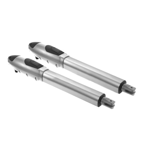
Swing gate openers
Hide thumbs
1
Table Of Contents
2
3
4
5
6
7
8
9
10
11
12
13
14
15
16
17
18
19
20
21
22
23
24
25
26
27
28
29
page
of
29
Go
/
29
Contents
Table of Contents
Troubleshooting
Bookmarks
Table of Contents
Table of Contents
Warnings
1 Product Description
Applications
Description of the Automation
Description of Devices
PW220/PW230 Electromechanical Gear Motors
PC160 Control Box
PKS-1 Key Selector
PPB-1 Push Button
Flashing Light
Radio Transmitter
PEL-1 Electric Latch and PS-1 Stopper
2 Installation
Notes of Motors in Operation
Tools in Installing
Motors, Components and Its Installation in Illustration
Power Connection
Notes for Power Connection
Installation
Preparation for Motor Installation
Installation of the Gear Motors
PKS-1 Key Selector
PPB-1 Push Button
Flashing Light
Photocells
PH-1 Photocells
PEL-1 Electric Latch and PS-1 Stopper
PC160 Control Box
3 Dip Switch Setting
Functional Switch and LED Lights Introduction
Transmitter Memorizing and Erasing Process
System Learning Process
Gate Operation
Gate-Moving Logic
4 Trouble Shooting
5 Technical Characteristics 5.1 PW220
Pw230
PC160 Control Box
Photocells
PKS-1 Key Selector
PPB-1 Push Button
Flashing Light
Transmitter
PEL-1 Electric Latch
6 Annexes
CE Declaration of Conformity
Advertisement
Quick Links
1
Pc160 Control Box
2
Pw220/Pw230 Electromechanical Gear Motors
3
Transmitter Memorizing and Erasing Process
4
System Learning Process
5
Pc160 Control Box
Download this manual
Table of
Contents
Previous
Page
Next
Page
1
2
3
4
5
Advertisement
Table of Contents
Need help?
Do you have a question about the PW220 and is the answer not in the manual?
Ask a question
Questions and answers
Related Manuals for PowerTech PW220
Gate Opener PowerTech PW150 User Manual And Warranty Statement
Swing gate openers for residential use 24v dc gear motor (20 pages)
Gate Opener PowerTech PW200 User Manual And Warranty Statement
Swing gate openers for residential use 24v dc gear motor (20 pages)
Gate Opener PowerTech PW230 User Manual
Swing gate openers (29 pages)
Gate Opener PowerTech PW320 User Manual
Swing gate openers 24v dc gear motor (20 pages)
Gate Opener PowerTech PW330L User Manual
Swing gate openers (21 pages)
Gate Opener PowerTech PA250 User Manual
Residential articulated arm openers 24v dc gear motor (21 pages)
Gate Opener PowerTech PC190 User Manual
Residential articulated arm openers 24v dc gear motor (21 pages)
Gate Opener PowerTech PL300E User Manual
Sliding gate openers (16 pages)
Gate Opener PowerTech PL500 User Manual
24v dc motor. sliding gate openers. for residential (17 pages)
Gate Opener PowerTech PL600H User Manual
24v dc motor. sliding gate openers. for residential (28 pages)
Gate Opener PowerTech KIT PL600 Manual
(25 pages)
Gate Opener PowerTech KIT PL600 Instructions Manual
Sliding gate openers (25 pages)
This manual is also suitable for:
Pw230
Table of Contents
Save PDF
Print
Rename the bookmark
Delete bookmark?
Delete from my manuals?
Login
Sign In
OR
Sign in with Facebook
Sign in with Google
Upload manual
Upload from disk
Upload from URL


Need help?
Do you have a question about the PW220 and is the answer not in the manual?
Questions and answers