Table of Contents
Advertisement
Quick Links
Advertisement
Table of Contents

Related Manuals for Datavideo SE-4000


Summary of Contents for Datavideo SE-4000
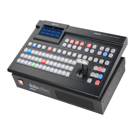
- Page 1 4K DIGITAL VIDEO SWITCHER SE-4000 Instruction Manual...
-
Page 2: Table Of Contents
Table of Contents FCC COMPLIANCE STATEMENT ....................6 WARNINGS AND PRECAUTIONS ..................... 6 WARRANTY ........................... 7 ........................7 TANDARD ARRANTY ........................7 HREE ARRANTY DISPOSAL ..........................8 CHAPTER 1 INTRODUCTION ....................9 ......................10 VERVIEW ....................12 ONTROL ANEL VERVIEW ................... - Page 3 ..........................38 .......................... 39 ..........................39 ETUP CHAPTER 5 GRAPHICAL USER INTERFACE ................41 ..........................49 TART Transition ..........................49 Type ............................49 Matte ............................50 Wipe Effects ..........................51 Wipe Border ..........................51 Wipe Position .......................... 52 ..........................53 EYER Keyer ............................
- Page 4 User Mems ..........................79 Load Memory ........................79 Save Memory ........................79 Still ............................79 Load Still ..........................80 Save Still ..........................81 Grab Still ..........................81 Delete Still ........................... 82 Loading still images ......................82 Clip ............................83 Logo ............................83 Load Logo ..........................
- Page 5 Datavideo Technologies is not responsible for any omissions or errors, or for any subsequent loss or damage caused by using the information contained within this manual.
-
Page 6: Fcc Compliance Statement
AC adapter. If you are not sure of the type of power available, consult your Datavideo dealer or your local power company. 8. Do not allow anything to rest on the power cord. Do not locate this unit where the power cord will be walked on, rolled over, or otherwise stressed. -
Page 7: Warranty
Your statutory rights are not affected. Three Year Warranty All Datavideo products purchased after July 1st, 2017 qualify for a free two years extension to the standard warranty, providing the product is registered with Datavideo within 30 days of purchase. -
Page 8: Disposal
PC components are covered for 1 year. The three-year warranty must be registered on Datavideo's official website or with your local Datavideo office or one of its authorized distributors within 30 days of purchase. Disposal For EU Customers only - WEEE Marking This symbol on the product or on its packaging indicates that this product must not be disposed of with your other household waste. -
Page 9: Chapter 1 Introduction
With a built-in 5-inch LCD touch panel, the SE-4000 provides a user friendly user interface, which is very easy to operate and set up. The SE-4000 switcher also has powerful and easy- to-use effects such as Chroma/Luma Key, DSK, PIP, DVE/Wipe Generator, still stores and logo insertion. -
Page 10: Main Unit Overview
1.1 Main Unit Overview The power button starts and The front panel on the SE-4000 main unit has a grille shuts down the SE-4000 for airflow cooling fans. Please do not block or cover main unit. this grille as the unit may overheat. This grille should also be kept free of dust. - Page 11 TALLY OUT The SE-4000 Tally Output port provides bi- RS-232 REMOTE colour tally information to a number of Connect a custom keyboard controller to AUDIO OUT DC IN GPI OUT other Datavideo products, such as the ITC- this port. Supports two channels of the XLR...
-
Page 12: Control Panel Overview
1.2 Control Panel Overview Perform video switching and other relevant controls on the Control Panel. 5 inch LCD Screen Keyer Selection Logos 1 & 2 SHIFT A touchscreen user interface Enabling the pre-assigned Logo insertion on Press the SHIFT button to allowing you to access keyers (Chroma, Luma, preview and program... - Page 13 The power button starts and shuts down the control panel power. Note: After the power button is pressed, you will be prompted on SERVICE Port DC IN 12V the 5 inch LCD screen to confirm the Connect the USB drive Connect the supplied shutdown.
-
Page 14: Connecting The Power Supply
1.3 Connecting the Power Supply Connect the DC output plug of the supplied AC adapter to the DC IN 12V connector on the rears of the switcher’s main unit and control panel and then connect the AC adapter to a power supply. -
Page 15: Chapter 2 Preparation
Output devices Connect the Control Panel to the Main Unit There are two methods to connect the SE-4000’s main unit to the control panel. You can establish point-to-point or network connection between the two devices. Local Connection Use a standard Ethernet cable to connect DVIP ports of the switcher’s main unit and control panel. - Page 16 Tap SCAN on the main menu to search for the main unit to connect.
-
Page 17: Network Connection
The control panel should detect one main unit named SE-4000. Select the detected device then tap Apply to establish connection. You can start using the switcher after the control panel has been connected to the main unit successfully. Network Connection Connect DVIP ports of the main unit and the control panel to a router. - Page 18 192.168.100.101 (Default) 192.168.100.102 (Default) (Subnet Mask: 255.255.255.0) (Subnet Mask: 255.255.255.0) 192.168.100.1 (Subnet Mask: 255.255.255.0) Note: The main unit, the control panel and the router should be assigned IPs that are in the same network segment. After establishing network connection between the main unit and the control panel, simply turn on the respective power switches.
- Page 19 Tap SCAN on the main menu to search for available main units.
-
Page 20: Connecting The Video And Audio Input Devices
You may detect up to 6 SE-4000 main units. Select one device from the list then tap Apply to establish connection. You can start using the switcher after the control panel has been connected to the selected main unit successfully. -
Page 21: When Linking Via Tally Connection
When linking via tally connection Connect the switcher’s tally OUT port to a commercially available tally box. The tally pinout information can be found in Appendix Tally Box Connecting the Video and Audio Output Devices Connect projectors, large displays and other video output devices to the video output ports on the rear of the main unit. -
Page 22: Network Setup
2.2 Network Setup The SE-4000’s main unit and control panel can be connected to the network via their DVIP ports. The available connection modes are fixed IP and DHCP which will be described in the next two sections. Static IP Configuration When new from the factory the SE-4000’s main unit and control panel will initially have... -
Page 23: Multi View
DHCP 2.3 Multi View The SE-4000 Multi view output can be supplied from the HDMI or SDI outputs, see Chapter 5 (5.6) for configuring the outputs. The Multi view shows monitoring images for Preview (PVW), Program (PGM) and Inputs 1~8. The Multi view can also show audio level bars overlaid on the Program image. - Page 24 The SE-4000 currently offers only one multi-view layout. More layouts will be added in the future. See Multiviewer Section 5.6 for the available options. Note: A Red tally indication box will be shown around the sources selected for Program OUT and these selected sources should be displayed at the switcher’s selected Program output(s).
-
Page 25: Chapter 3 Device Initialization
Chapter 3 Device Initialization After the SE-4000 is booted up, there are initial settings that you should configure on the GUI. These initial settings will be discussed in this chapter. You should see the GUI shown below on the LCD screen. - Page 26 Tap the Setting button to change the button icons or swap the settings between the selected user memory slots. Icon: Tap to select an icon for the selected user memory slot. Swap: Follow the steps outlined below to swap the contents of two user memory slots. First tap a user memory slot.
-
Page 27: Wipe Effects
3.2 WIPE Effects Open the Wipe page to select a wipe effect. Tap the REV button to reverse the default wipe direction. Tap the Setting button to configure the wipe borders. Enable the border first then adjust its hue, softness and width. 3.3 PIP In the P-in-P tab, you will be allowed to select how you would like to position the PIP window on the Preview and Program screens. -
Page 28: Pip Icon
PIP Icon Tap the Edit button to select an icon. To restore the defaults, simply tap the Reset button. PIP Setting On the PIP Setting page, you can select a video source for the PIP window and set the window position and size. -
Page 29: Aux
3.4 AUX In AUX tab, you will be allowed to assign a video source for the output ports. See all available options in the Source pane. 3.5 Still On the Still page, you can assign different still images to the input channels. Follow the steps below to make the selection: First select an input channel then a still image. -
Page 30: Keyer
Delete and Layout buttons are described below: Delete: Tap to delete the selected still image. Layout: Tap to select the still image pane layout. You can either display three (1 x 3) or eight (2 x 4) thumbnails at the same time. 3.6 Keyer On the Keyer page, you can configure Keyers 1 –... -
Page 31: Adjust
For luma keyers, the Invert button allows you to select the background color to be keyed. When the Invert button is disabled, the luma keyer removes the black background; when the Invert button is enabled, the luma keyer removes the white background. DSK 1/2 are usually set to Linear keying mode which is chosen for professional graphic design. -
Page 32: Cross Point
3.7 Cross Point The Cross Point function allows the user to shuffle contents of Inputs 1 – 8 without changing physical connections at the back of the machine. First select an input channel then tap Video XPT or Audio XPT to set the respective sources. In Audio XPT, if “FOL.”... -
Page 34: Chapter 4 Software Setup For Switcher
Software Setup for Switcher The Switcher Image Import/Export software allows the user to import still images, animated clips, still logos, animated logos and custom user settings to the SE-4000 from a laptop/PC. To use the Switcher Image Import/Export software, you should connect the control panel to the main unit using the network method. -
Page 35: Home
Once selected, click OK to start the scanning process. Note: Please make sure that the selected interface card is in the same network segment as the SE-4000. The software should connect with the switcher’s main unit over the IP set up in Section 2.2. -
Page 36: User
4.2 User Click the User button to view all the .mem files saved on the switcher. To import .mem files from your PC, click “User” then enter a memory location. Click “Import User” to browse your hard drive and select the user memory file that you would like to import. -
Page 37: Still
4.3 Still Click the Still button to view all the still images saved on the switcher. To import still image files from your PC, click “Still” then enter a memory location. Click “Import Still” to browse your hard drive and select the image file that you would like to import. -
Page 38: Logo
4.5 Logo Click the Logo button to view all the still logo images saved on the switcher. To import still logo image files from your PC, click “Logo” then enter a memory location. Click “Import Logo” to browse your hard drive and select the logo image file that you would like to import. -
Page 39: Ani-Logo
4.6 Ani-Logo Click the Ani-Logo button to view all the animated logos saved on the switcher. To import animated logo files from your PC, click “Ani-Logo” then enter a memory location. Click “Import Ani-Logo” to browse your hard drive and select the animated logo that you would like to import. -
Page 41: Chapter 5 Graphical User Interface
Chapter 5 Graphical User Interface The switcher’s GUI menu allows the user to perform several configurations of image effects, such as Picture-in-Picture, chroma key, subtitle overlay, transition effects, still pictures, etc. The user can also configure the I/O by selecting different input and output combinations. In addition, in the setup menu, the user is allowed to adjust the keyboard brightness, set the menu language, reset the device, customize network settings and upgrade the firmware. - Page 42 Border Color Hue (0 - 359 Default: 0) Horizontal Position (-100 - 100% Default: 0%) Position Vertical Position (-100 - 100% Default: 0%) Key 1 Key 2 Key 3 Keyer Selection (Default: Key 1) Key 4 Keyer DSK 1 DSK 2 Fine: High keying quality Fine / Normal Normal: Original keying quality...
- Page 43 Input 7 Input 8 Black (Default) Left sets the left edge of the keyer mask (0 – Left 100%; Default: 0%). Right sets the right edge of the keyer mask (0 Right – 100%; Default: 0%). Mask Top sets the top edge of the keyer mask (0 – 100%;...
- Page 44 Trims the left edge of the key object (0 - 100% Left Default: 0%). Trims the right edge of the key object (0 - Right 100% Default: 0%). Distinctiveness of key edge (0 - 100% Default: Soft Left sets the left edge of the keyer mask Left (Default: 0%).
- Page 45 PIP Border Color Saturation (0 - 100% Default: PIP Border Color Hue (0 - 359 Default: 0) Width PIP Border Width (0 - 100% Default: 0%) Distinctiveness of Border Edge (0 - 100% Soft Default: 0%) Opac Border transparency (0 - 100% Default: 0%) Direction Direction of light source (0 - 359 Default: 0).
- Page 46 Audio volume of a selected video input (-64 – Gain 24 dB Default: 0 dB). Audio Audio delay of a selected video input (0 – 340 Delay ms Default: 0 ms). Input 1-8 Assign the selected input source to an input Crosspoint button (Default is Input 1).
- Page 47 Audio out volume Gain Range: -60 – 24 (dB) with default = 0 dB Audio out delay Delay Range: 0 – 340 ms with default = 0 ms Opens a numeric Memory Selection from 1 to 1000 (Default: keypad to enter a Load Memory None) memory location...
- Page 48 Resets the Multiviewer labels to the default Reset Input Names settings English Language Traditional Chinese Simplified Chinese SE-4000 DHCP On/Off (Default: Off) SE-4000 IP Address 192.168.100.101 (Default) Main Unit SE-4000 Network 255.255.255.0 (Default) Network Mask CTL DHCP On/Off (Default: Off) CTL IP Address 192.168.100.102 (Default)
-
Page 49: Start
M/E value defined by the user setting. Type The SE-4000 provides four major types of transition effect, which are Clip (Stinger), WIPE (2D) and Mix. Please note in addition to selecting the transition effect in the menu, you can also press MIX, WIPE or STINGER button to enable the respective transition effects. -
Page 50: Matte
For MIX effect, set the transition time in “Start Transition M/E.” For WIPE effect, set the relevant WIPE settings in “Start WIPE Effects.” Matte The user can open the Matte view by pressing the BG button of the Program and Preview button rows. -
Page 51: Wipe Effects
The Sat or Saturation value refers to the intensity of the color selected in Hue. As the saturation increases, the color appears to be more pure. As the saturation decreases, the color appears to be more washed-out or pale. The Luma value relates to how bright or dark the selected color or hue is. The higher the Luma value, the brighter the color selected in Hue. -
Page 52: Wipe Position
Wipe Position Position allows the user to adjust the center position of certain wipes (e.g Circle & Elipse). X represents the horizontal position and Y is the vertical position. Horizontal Position (X) Positive value moves the wipe center to the right. Negative value moves the wipe center to the left. -
Page 53: Keyer
5.2 Keyer Keyer of the SE-4000 provides the user with the capability of image keying. In this sub menu, the user will be able to configure the eight keyers available on the SE-4000. Keyer The 6 keyer options are Key 1, Key 2, Key 3, Key 4, DSK 1, and DSK 2. - Page 54 Please note that if you select Full, the keying effect will be disabled, keeping the original source image. For example, if you select Full PIP, no keying effect will be applied to the PIP image source. After the keying mode is chosen, select Self if only one source is required for the keyer, which is Key source.
-
Page 55: Key Source
parameters in the Chroma sub menu. To enable the P-in-P window with the chroma key effect applied, press Key 1 PGM or PVW button on the switcher’s control panel. Key Source This option allows you to select the key and fill sources. Select the key source from the list below: ... -
Page 56: Chroma
Left – Left sets the left edge of the keyer mask. Right – Right sets the right edge of the keyer mask. Top – Top sets the top edge of the keyer mask. Bottom – Bottom sets the bottom edge of the keyer mask. 5.3 Chroma The Chroma Keyer removes the green background of the key image. -
Page 57: Key Source
Select Fine if you require high keying quality and Normal for original keying quality. Next, select one video source from all available options in Key Source. Key Source Assign a key source to the keyer selected. Various options are listed below: ... - Page 58 Outlined below are steps to set key tie with the chroma keyer. 1. First, in the Keyer menu, select the keyer and set it to Chroma. We used Key 1 in this example. 2. Open the Chroma menu and select Key 1. Select a foreground image from the Key Source list (the foreground image is usually a person or an object against a green backdrop).
- Page 59 3. Enable Key Tie and on the right, select a background image. Below are available sources of the background image: Input 1 – 8 Off Note: You will not be able to use the keyer button once key tie is enabled. Use the input button that is assigned the background image to open the key tie image.
-
Page 60: Ck Setup
CK Setup In CK Setup, the user will be able to find all the parameters needed to perform chromakeying of the green or blue backdrop. CK Auto: This function automatically calculates the best Hue & Luma values for the current Keyer source. -
Page 61: Mask
K Range (Key Range): Key Acceptance sets the range of hues or colors (0 – 360 degrees) that closely match the background color to be keyed. The user can start with a value of 120 degrees and this value can be fine-tuned up or down depending on the setup of the green or blue screen studio. -
Page 62: P-In-P
Left – Left sets the left edge of the keyer mask. Right – Right sets the right edge of the keyer mask. Top – Top sets the top edge of the keyer mask. Bottom – Bottom sets the bottom edge of the keyer mask. 5.4 P-In-P The P-in-P menu allows the user to adjust various parameters for the PIP window. -
Page 63: Position
Position The user can adjust the P-in-P window position by adjusting values of X, Y and SIZE with the corresponding sliders, where X is the horizontal position, Y is the vertical position and Size is the PIP screen size. X-Value Positive value: position the P-in-P window to the right. -
Page 64: Crop
Size Ranges from 0 to 100 with 1% being the smallest and 100 being the largest. So 50% would represent a P-in-P window which is half the size of the background image. 100% would see the PIP image totally cover the background image unless offset to one side. - Page 65 The SE-4000 offers various border styles listed as follows: Border Off Normal Shaded* 3D Bevel** Bevel Shaded* Dual Bevel** Bevel Flat** Flat Bevel** 3D Glass** Glass Shaded* Dual Glass** ...
-
Page 66: Shade Matte (Dual Color Border)
The borders can also be widened or narrowed by adjusting Width. Please note that a width of zero (0) will turn the PIP border off. Note: You will sometimes see black thin lines on your PIP image after setting the PIP border to Normal with a border width of zero. - Page 67 Shade Matte determines the inner border. The boundary between the normal border matte and the shade matte can be determined by adjusting the Shade Position parameter. Border Matte Shade Matte Shade Matte Border Matte Luma, Sat and Hue The color of the Shade Matte can also be controlled by adjusting the Hue, Sat and Luma values.
-
Page 68: Inputs
Shade Soft This blurs or softens the Shade Matte area. Shade Position The position of the boundary line between Shade Matte and Border Matte is controlled by the Shade Pos value. Increasing this value moves the boundary line such that the Shade Matte occupies less of the width of the border. -
Page 69: Input
Input In this sub menu, you will be allowed to set the mode of display for the respective Input windows of the Multiview display. First select the input that you would like to configure and then for each selected input, set the mode of input by selecting one of the modes from the first mode option: ... -
Page 70: Audio
Audio Gain (0 – 24 dB): adjustment of the input audio volume for the selected video input. Delay (0 – 340 ms): sets the delay of the audio component of the selected video input. Crosspoint The crosspoint function allows the user to shuffle the contents of Inputs 1-8 without changing the physical connections at the back of the machine. -
Page 71: Audio Xpt
Audio XPT The Audio XPT feature allows the user to associate the audio component of any input source to any of the input buttons (1 – 8), thus cross assigning audio input channels to program/preview row buttons. Available options are listed as follows: ... -
Page 72: Outputs
This menu allows the user to configure various output settings such as video output, tally mode and GPI connection. Outputs In general, the SE-4000 offers 7 output ports (SDI 1 – 4 / HDMI 1-3) and all 7 ports can be configured to output one of the following: Input 1 – 8 ... - Page 73 The SE-4000 Multi-view monitoring is available in different multi-image layouts. These outputs can be used to monitor video and audio in a number of different configurations. For each setup, embedded audio level indication is also available on all inputs as well as the Preview and Program windows.
-
Page 74: Tally Mode
Program window. This option allows you to switch their positions. Tally Mode Tally output port generally sends two tally signals to each channel. In Datavideo products, Red indicates On-Air, and Green indicates next video source. On the Multiview screen, the tally... -
Page 75: Gpi Out
Preview window, the tally lights will be enabled Green, and the color is changed to Red as soon as the transition is triggered. GPI Out GPI is designed to allow the user to trigger playback of an external playback device such as Datavideo’s HDR-80/90. GPI OUT allows the user to configure your GPI connection. -
Page 76: Audio
HDMI videos. Audio External audio source can only enter the SE-4000 via the analog XLR input port found on the rear panel of the main unit. Ideally the user should use the SE-4000 with an audio mixer. It is recommended to use AD-200 audio mixer designed and manufactured by Datavideo. All external audio sources can be connected to AD-200 before entering the SE-4000. -
Page 77: Pgm Audio
Mode (ON/OFF): Setting Mode ON allows the SE-4000 to embed external audio component into SDI video out. Changing the Mode option from ON to OFF will mute the embedded audio. Audio Src: This sub-option allows the user to select the audio source. -
Page 78: Analog Out
Mode (V Fade/X Fade) While working in the Audio-F-Video mode, the audio sources will also change as the video sources are switched. We can choose how the audio changes sources, whether it be a clean cut (immediate switch) or some sort of transitioned change (cross fade or fade out & in). To do this we would need to set up with the following menu options. -
Page 79: Files
Still STILL image is an image pre-loaded to the SE-4000’s input buffers (Input 1-8). The Still menu allows users to load still pictures from the machine’s internal memory to the input buffer, save still pictures to the machine’s internal memory, view thumbnail pictures and grab... -
Page 80: Load Still
Load Still Upon selecting “Load Still”, the user can then choose the memory location from which the still image is loaded. The system memory can store up to still images. The following are destinations to which the still image can be loaded: ... -
Page 81: Save Still
Save Still “Save Still” allows the user to save the still image to a specific memory location. The user should determine the source of the still image first. The available sources are listed below: Inputs 1 – 8 To complete the save, the user can simply tap “Save” after determining the memory location. Grab Still “Grab Still”... -
Page 82: Delete Still
“Yes” to confirm the delete. Loading still images The SE-4000 allows the user to load still images saved on the machine to the Multiview screen. Please follow the steps outlined below to load the still picture. 1. Press the FILES button to open the menu on the 5 inch LCD screen. -
Page 83: Clip
3. First select a destination to which the still picture will be loaded then the still picture. Lastly, tap Load to load the still picture to the selected destination. For more still functions such as file import from the PC or laptop, see Section 6.3 Managing Still Pictures. -
Page 84: Load Logo
to the machine’s internal memory, view thumbnail logo pictures and adjust the logo positions. Load Logo Upon selecting “Load Logo”, the user can then choose the memory location from which the still logo image is loaded. The system memory can store up to 1000 still logo images. Select “Load”... -
Page 85: Delete Logo
Delete Logo First move to a memory location, then select “Delete” to remove the still logo from the selected memory location. Positioning The logo can be manually positioned by adjusting its XY coordinates. Note that the origin of the coordinate system is at the center of the screen. X: A positive value indicates that the logo is in the right half of the screen and a negative value indicates that the logo is in the left half of the screen. -
Page 86: Load Ani Logo
Load Ani Logo Upon selecting “Load Ani Logo”, the user can then choose the memory location from which the animated logo is loaded. The system memory can store up to 1000 logo animations. Select “Load” to load the animated logo to the chosen destination (Logo 1/Logo 2). Note: To import custom logo animations from your computer, see chapter 6.6 Enabling Logo Animation... -
Page 87: Delete Ani Logo
5.9 Setup In the “Setup” menu, the user can change the resolution, reset the SE-4000 to its Factory Default values, enable/disable Auto Save, choose the preferred menu language, upgrade firmware and view the current firmware versions (Interface, Mainboard and Keyboard). -
Page 88: Genlock
Level There are two different audio standards available for selection. The user can either select the EBU or SMPTE standard. By selecting AUTO allows the device to automatically detect the audio standard. Note: When the image is 50 Hz, the audio follows EBU standard and when the image is 59.94/60 Hz, the audio follows SMPTE standard. -
Page 89: Keyboard
Keyboard In Keyboard, you will be allowed to adjust the keyboard brightness with 7 being the brightest and 1 being the dimmest. Auto Save When enabled, your last settings will be automatically saved within 5-10 seconds after exiting the GUI menu. Do not shut down your machine during this time. At the next boot, the machine will automatically load the last saved settings. -
Page 90: Factory Def
The Auto Save function does not apply to the resolution setting. To change the SE-4000’s resolution, go to “GUI Menu/Setup/Standard” and then select “Save Setup” to save the new resolution setting. Factory Def Factory Default: Tap Restore to reset the machine to factory default settings. -
Page 91: Network
Section 2.2 for network setup. SE-4000 and CTL refer to the switcher’s main unit and control panel respectively. DHCP: The available network connection modes are DHCP and Static. The default connection mode is Static (DHCP turned off). The default IP addresses of the main unit and the control panel are 192.168.100.101 and 192.168.100.102 respectively. -
Page 92: Software
Network Def: resets network settings to factory defaults. Default settings are listed below. DHCP: Off IP Address: 192.168.100.101 (SE-4000) and 192.168.100.102 (CTL) Network Mask: 255.255.255.0 Once all settings are entered, tap Save to save all changes made and reboot the device to apply the new network settings. -
Page 93: Chapter 6 Basic Operation
Note: The keys on the Program and Preview rows will still be active while the T-Bar is moving. Source Row The SE-4000 allows you to simultaneously activate 8 live channels out of the available 12 input channels. As a result, channels 3/4/7/8 are designed to be shared channels, allowing you to switch between SDI and HDMI input ports (see the input video port labels at the rear of the main processing unit). -
Page 94: Black And Background Matte View
The Transitions group of buttons allows the user to decide how to bring the selected Preview / Next source image to the Program output. The SE-4000 user can decide to use a CUT, MIX, WIPE or Stinger (Animated Effect) transition. -
Page 95: Cut Button
Note: The Stinger transition is currently under development so the function cannot be used. CUT Button The CUT button is used to immediately switch between the currently selected Program and Preview sources. MIX Button The MIX button is selected when a dissolve or fade transition between the selected Program and Preview sources is required. -
Page 96: T-Bar
Program output. WIPE Selection MENU There are 32 different 2D WIPE effects to choose from when using the SE-4000 switcher. To select a different WIPE transition select a WIPE style in the Start Item of the GUI Menu (see... - Page 97 Before you make the selection, make sure the TRANS BG and WIPE buttons are enabled. Note: Open the GUI menu by pressing the HOME button in the MENU area of the SE-4000 Control Panel. To select a WIPE on the GUI menu, navigate to the WIPE option under WIPE EFFECTS and then select a WIPE number.
-
Page 98: Managing Still Pictures
Each video channel of the SE-4000 has one frame store to which a still can be loaded, and the unit has enough storage space for up to 250 uncompressed stills. -
Page 99: Loading An Existing Logo From Memory
Loading an existing Logo from Memory The SE-4000 allows the user to load still logo from the machine’s memory to the logo buffer (Logo 1 or 2), then press either Logo 1 or Logo 2 button to enable the loaded logo on both the Preview and Program Out. -
Page 100: Importing Still Logo From The Pc
To load a still logo, simply select a logo buffer first then browse to a still logo number and lastly select 'Load'. The selected still logo should be loaded into the selected buffer. To adjust the logo position, simply change the X and Y values of the respective logo buffer which can be found at the bottom of the Logo menu. - Page 101 3. Click “Logo” number then enter a memory slot number. Click “Import Logo” to open the file browser window and browse to the file that you would like to import. 4. Select the logo file that you would like to import. Note that the aspect ratio is limited to 480x1080.
-
Page 102: Enabling Logo Animation
Loading an existing Ani-Logo from Memory The SE-4000 allows the user to load ani logo from the machine’s memory to the logo buffer (Logo 1 or 2), then press either Logo 1 or Logo 2 button to enable the loaded ani logo on both the Preview and Program Out. -
Page 103: Importing Animated Logo From The Pc
2. Tap Load Ani Logo. On the page shown above, you should find a thumbnail view of three animated logos. Use the right/left arrow buttons at the bottom of the page to browse all other animated logos which are shown in numerical order. Blank thumbnails are unused memory slots. To load an animated logo, simply select a logo buffer first then browse to an ani logo number and lastly select 'Load'. - Page 104 2. Clicking the Ani-Logo button to view animated logo thumbnails and import animated logos from your PC to the switcher. 3. Click “Ani Logo” number then enter a memory slot number. Click “Import Ani-Logo” to open the file browser window and browse to the file that you would like to import. 4.
- Page 105 5. Check on the program’s Ani Logo page to make sure that the animated logo has been imported successfully. 6. After successfully importing the animated logo into the switcher, you will then be able to start loading the new animated logo to the buffer. To enable the animated logo on Preview and Program Out, press the Logo button.
-
Page 106: Chapter 7 Advanced Operation
Chapter 7 Advanced Operation The SE-4000 is a High Definition Digital Video Switcher. As well as mixing video and audio sources, it has additional functions such as Picture In Picture (PIP), DSK, LUMA KEY, Chroma Key and Logos. Before attempting to use the SE-4000’s PIP, DSK LUMA KEY and LOGO functions it may help to first understand the order of the video layers at the SE-4000 Program (PGM) outputs. -
Page 107: Picture-In-Picture And Downstream Key
DSK layers can also stop the video layers behind them from being displayed properly. The SE-4000 has six dedicated keyers, Key1, Key2, Key3, Key4, DSK 1 and DSK 2. All six keyers can be active simultaneously. In the following sub-sections, we will provide you with... -
Page 108: Picture-In-Picture
Picture-In-Picture In this example, we are supplying the SE-4000 with an HD-SDI live video signal to input 2; this is selected on the Program row. We have also assigned a STILL image to input 6. This still image, selected on the Keyer sub menu, will be displayed in the PIP window. -
Page 109: Assigning A Video Source To A Pip Window Using Shortcut Keys
3. Activate the PIP window on the Preview or Program output by pressing Key 1 PVW or Key 1 PGM button so that you can adjust the PIP window while viewing the changes made. 4. Open the P-in-P menu and adjust the PIP window settings (positions, border, shade matte and crop). -
Page 110: Placing Text On The Video Using Luma Key
1. Connect the laptop to the switcher’s HDMI Input Port 9 (Input Channel 3). 2. On the SE-4000 control panel, press the Keyer button to open the Keyer menu on the 5 inch LCD screen. - Page 111 5. In this example, the text image is against a black background so reduce the Lift value to remove the black background. Descriptions of the corresponding parameters are described below: Lift (0 – 100%) adjusts the dark/black areas of the key image. Reducing the value of Lift will make dark areas of the key image more transparent.
-
Page 112: Insertion Of People Onto Backgrounds (Chroma Key)
Key basics. The camera, backdrop and lighting all play an important role in producing the optimal Chroma Key result. Although the SE-4000 is equipped with excellent keying controls, it is best to start with a good keyable image. A good foreground image helps produce a good key... - Page 113 Three chip/Three sensor camera We strongly recommend the use of a three chip or three sensor camera for Chroma Key shooting. If the camera has three chips or sensors then this usually means good colour separation within the camera. The optics on these cameras are usually better too. The extra image clarity and the good colour separation help improve the quality of the subsequent keying with the camera’s output.
- Page 114 SDI Input 1 at the rear of the switcher. To configure the settings that will be used for chroma keying, press the MENU button on your SE-4000 control panel to open the GUI menu on the monitor. Follow the steps below to configure the chroma key settings.
- Page 115 3. Select the camera source in “Key Source.” In this example, we have selected Input 1, which corresponds to the SDI Input 1 at the rear of the switcher and therefore the port to which the camera is connected. 4. Adjust the left, right, top and bottom values of “Mask” to set the chroma key range according to the green or blue backdrop size.
- Page 116 Note: Selection of CK Auto automatically calculates the best Hue & Luma values for the current Keyer source. The chroma keyer parameters are described below: Hue: This parameter adjusts the color of the chroma key. A typical green screen value will be around 120.
- Page 117 K Fgnd (Key Foreground): Key Foreground adjusts the performance of the chroma key in light or white areas. Apply more Key Foreground if the light areas are becoming too transparent. K Bgnd (Key Background): Key Background adjusts the performance of the chroma key in dark or black areas.
-
Page 118: Appendices
Chapter 8 Appendices Appendix 1 Tally Outputs Dielectric strength: Max. DC 24V The SE-4000 has a D-sub 25 pin female tally output port. These connections provide bi-colour tally Current: Max. 50mA information to a number of other Datavideo products, such as the ITC-100 eight channel talkback system and the TLM range of LCD Monitors. - Page 120 GPI / GPO switch. The GPI interface is a 3.5mm Jack Socket which is situated on the rear panel of the SE-4000. Contact closure between the Outer and Inner contacts on the jack plug will trigger a user selected event.
- Page 121 The user is allowed to connect a custom keyboard controller to the SE-4000 via RS-232 interface (the user may also enable RS-422 if necessary). The table below provides the RS-232 serial port pinout on the device end (SE-4000). Note that the RS-232 port is a 9 pin D-sub female connector.
-
Page 122: Appendix 4 Firmware Update
Firmware Update Datavideo usually releases new firmware containing new features or reported bug fixes from time to time. Customers can either download the SE-4000 firmware as they wish or contact their local dealer or reseller for assistance. The existing SE-4000 settings should persist through the firmware upgrade process, which should not be interrupted once started as this could result in a non-responsive unit. - Page 123 5. Insert the USB drive into the Service port at the rear of the control panel. 6. Power ON the control panel then press the Setup button to open the Setup menu on the built-in 5 inch LCD screen. . 7.
-
Page 124: Appendix 5 Frequently-Asked Questions
Appendix 5 Frequently-Asked Questions This section describes problems that you may encounter while using the SE-4000. If you have any questions, please refer to related sections and follow all suggested solutions. If problem still exists, please contact your distributor or the service center. -
Page 125: Appendix 6 Dimensions & Weight
Appendix 6 Dimensions & Weight Main Unit Control Unit Weight: 7.1 kg All measurements in millimeters (mm) -
Page 126: Appendix 7 Specifications
Appendix 7 Specifications Model Name SE-4000 Product Name 4K 8-Channel Digital Video Switcher Video Standard 4K & HD Input 3840x2160p: 60/59.94/50 1080p: 60/59.94/50 Video Format Output 3840x2160p: 60/59.94/50 1080p: 60/59.94/50 SDI: 4:2:2 Video Processing HDMI: YUV 4:2:2 10 bit, RGB: 4:4:4 8/10 bit... - Page 127 Logo Insertion Still Store Effects FTB, Cut, 32 Wipe with border Transition Preview Full Transitions Preview Sync / Reference In / Tally Output 1 x D-sub 25pin, Dual Color PC Remote Control DVIP (Ethernet) Built-in Audio Mixer Firmware Update Ethernet Special Features 5 inch touchscreen display Chassis...
-
Page 128: Service And Support
Service and Support www.datavideo.com/product/SE-4000 Mar-03.2023 Datavideo Technologies Co., Ltd. All rights reserved 2020 Version E1...
Need help?
Do you have a question about the SE-4000 and is the answer not in the manual?
Questions and answers