
Related Manuals for Sony RM-IP500


Summary of Contents for Sony RM-IP500
-
Page 1: Remote Controller
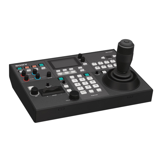
4-696-257-11(1) Remote Controller Operating Instructions Before operating the unit, please read this manual thoroughly and retain it for future reference. RM-IP500 © 2017 Sony Corporation... -
Page 2: Table Of Contents
Operating the Camera Setup Menu from the Unit Table of Contents (Camera Menu Operation Mode) ...... 35 Buttons and knobs used for camera menu operations ............35 Setting Specific Functions using Shortcuts Introduction (FUNCTION Menu) ........... 37 Using This Manual ..........4 Buttons and knobs used for FUNCTION menu operations ............ - Page 3 Trademarked items are not indicated by ® or ™ symbols in this manual. Data and security • SONY WILL NOT BE LIABLE FOR DAMAGES OF ANY KIND RESULTING FROM A FAILURE TO IMPLEMENT PROPER SECURITY MEASURES ON TRANSMISSION...
-
Page 4: Introduction
Terminology in this document push auto focus, AE (Auto Exposure) function, one- The RM-IP500 is referred to as the “unit” or “remote push auto white balance, and backlight compensation, controller” in this document. -
Page 5: Location And Function Of Parts
Location and Function of Parts The functions controlled by the buttons and knobs vary depending on the target camera to control. For details, see “Function of Buttons/Knobs in Each Block by Camera Model” (page 41). Color adjustment Menu control Camera selection block (page 5) block (page 6) block (page 7) - Page 6 A 1-a R-BLACK knob H ASSIGN 1 button, ASSIGN 2 button, ASSIGN 3 1-b B-BLACK knob button 1-c MASTER BLACK knob Executes functions assigned to each button on the Adjusts the R black, B black, and master black of target camera. the target camera.
-
Page 7: Lcd Panel
G CAM MENU button GAIN button: Press this button to display the gain value settings screen for the camera on the LCD Press and hold this button to display the setup menu panel. of the camera on the monitor output of the camera. SHUTTER button: Press this button to display the Nothing is displayed on the LCD panel of the unit. - Page 8 G AUTO FOCUS mode button Switches between automatic (button is lit) and manual (button is not lit) focus adjustment mode on the target camera. For details, see “To adjust the focus automatically” (page 31). H O.P.A.F (one-push auto focus) button Press during manual focus adjustment mode to execute one-push auto adjustment.
- Page 9 B DIRECT RECALL button Controls the pan, tilt, and zoom operation of the Recalls a preset stored in the target camera. Direct target camera. recall mode is enabled when the button is lit. Press Pan/tilt: Incline the joystick left/right to rotate the PRESET 1 to PRESET 10/0 to recall the stored camera counterclockwise/clockwise (pan left/ settings immediately.
-
Page 10: Rear
2 Connect an AC adapter. Rear Cord clamper Cord of the AC adapter 3 Thread the cord of the AC power adapter through the cord clamper, then close the lock. Anti-theft wire attachment point Attach a wire to prevent theft. Ground connection C GPI I/O connector Used as a tally input from an external device or as a... -
Page 11: Side / Front
Removing the screw hole protective covers Side / front Bend the tip of a thin rod about 2 mm, and insert it into the hole of the screw hole protective cover. Use a paper clip or other object with a diameter of about 1 mm. -
Page 12: Menu Operations
For details, see “Setting Specific Functions using Menu Operations Shortcuts (FUNCTION Menu)” (page 37). The menu control block is used to configure the device Basic menu operations settings and camera settings. Buttons and knobs used for RM menu operations Operation Buttons and knobs used OPERATION CONFIG, AUTO IP SETUP,... - Page 13 Typical RM menu operation The cursor moves up/down as the SELECT knob is turned. Turn the VALUE knob to select the setting. Cursor Selected setting Press the RM MENU button, turning it on (button is lit yellow). The RM menu top menu appears. To configure items in other menus Press the CANCEL button to return to the parent item in Turn the SELECT knob to move the cursor to the...
-
Page 14: Getting Started
VISCA over IP (LAN) connection Getting Started VISCA over IP (LAN) connection is configured using the following sequence. Setting the IP address of the unit (page 14) Connections You can connect the unit to cameras using VISCA over Connecting remote controllers, cameras, and setup PC IP (LAN) connection or VISCA RS-422 (serial) using LAN connection (page 16) connection. - Page 15 The LAN menu appears. Upon rebooting, the IP address setting is completed. The MAC address is displayed at the bottom. Turn the SELECT knob to move the cursor to IP. Set the IP address using the SELECT knob and VALUE knob/button. The default setting is 192.168.0.10.
- Page 16 Connecting remote controllers, cameras, and setup PC using LAN connection Connection example BRC-H900 1 2 3 1 2 3 4 5 6 7 8 9 IR SELECT RM-IP500 VISCA RS-422 RGB/COMPONENT DC IN 12V IN VISCA RS-232 OUT EXT SYNC IN...
- Page 17 IP control card is set to 192.168.0.100 by factory default. • Connecting stackable switching hubs in up to 2- tier configuration is recommended to avoid network delay. Notes • Do not connect more than 100 cameras, five remote controllers, and one setup PC across all networks, even if controlling a camera that is on a network of a different segment via a router.
- Page 18 qs Check the camera assignment result using AUTO IP SETUP >CAMERA TABLE in the RM menu. For details about displaying CAMERA TABLE, see “To check the camera table” (page 20). Assignment using AUTO IP SETUP >ASSIGN CAM This method is used to assign camera numbers to 1 Turn the SELECT knob to move the cursor to cameras that already have a configured IP address.
- Page 19 Turn the VALUE knob to change NO to YES, then press the VALUE button. To swap camera numbers You can change the camera numbers after IP addresses have been configured automatically. Press the RM MENU button, turning it on (button is lit yellow).
- Page 20 Turn the SELECT knob to move the cursor to LOWER display UPPER display SWAP A<=>B. < C A M E R A T A B L E > < C A M E R A T A B L E > pSWAP A<=>B : NOT EXEC p G R O U P N U M...
-
Page 21: Visca Rs-422 (Serial) Connection
Camera with RJ-45 connector RAUD RATE VISCA RS-422 IR SELECT (PLUG IN POWER) SYSTEM SELECT HDMI OUT SDI OUT RM-IP500 For connection of multiple cameras to a single remote controller RM-IP500 Camera Camera Camera Camera with RJ-45 with RJ-45 with 9-pin... - Page 22 TXD_IN+ RXD_IN - RXD_IN + 1st camera Camera with 9-pin connector VISCA RS-422 connector (connector block) RXD_OUT - RXD_OUT+ TXD_OUT- TXD_OUT+ RM-IP500 Remote Controller RXD_IN - VISCA RS-422 connector (RJ-45) RXD_IN+ RXD_OUT - TXD_IN- RXD_OUT+ TXD_IN+ TXD_OUT- TXD_OUT+ NC = No connection (not used)
- Page 23 Configuring a serial connection connection or changing the baud rate, prompting you to reboot the unit. After cameras are connected correctly, select serial connection using CONFIG >SERIAL in the RM menu, set the baud rate, and assign camera addresses. Note If a connected camera is changed after completing the configuration, the cameras must be configured again.
-
Page 24: Connection With A Video Switcher
SDI OUT BRC-X1000, SRG-360SHE BRC-H900 BRC-H800 Video signal Video signal Video signal MCX-500 Multi-Camera Live Producer RM-IP500 To video monitor Tally signal Tally/contact signal: Connection cable with D-sub 15-pin connectors Video signal: HDMI cable Video signal: Connection cable with BNC connectors... -
Page 25: Using A Setup Pc
The UPDATE MODE setup screen appears. The [Backup/Restore] screen appears. Turn the VALUE knob to change OFF to ON, then Click the [Backup] button. press the VALUE button. The configuration data backup starts. The default file name of the configuration data file is rm-ip500.cfg. -
Page 26: Loading A Saved Configuration File Into The Unit Or Another Remote Controller (Restore)
Loading a saved configuration file Note into the unit or another remote To use the RM-IP Setup Tool, set MAINTENANCE >UPDATE MODE to ON in the RM menu. controller (Restore) Access the URL of the remote controller to which you want to load configuration data using a web browser on the PC. -
Page 27: Operations
up. When the camera is off (standby), the button is not Operations lit. • You can turn all cameras registered in the camera table Before operation, make sure that cameras, the unit, and on/off (standby) at the same time by setting CONFIG peripheral devices are installed and connected correctly. -
Page 28: Selecting A Camera When Using Serial Connection
Selecting a camera when using Tally input change Target camera serial connection No tally input The CAMERA 1 to CAMERA 10 buttons for all target cameras can be You can select a camera number using the CAMERA 1 selected. to CAMERA 7 buttons. Change from no tally The camera corresponding to the tally The pressed CAMERA button lights in yellow, and the... -
Page 29: Operating A Camera
To face the camera toward the front (pan/ Operating a Camera tilt position reset) Press and hold the button on the joystick. Pan and tilt control Speed adjustment Pan/tilt position reset If you accidentally move the camera head with your hand Press the P/T RST (pan/tilt reset) button to reset the pan/ tilt position. -
Page 30: Zoom Control
In this case, press the P/T RST (pan/tilt reset) button to Release the joystick to stop zooming. reset the pan/tilt position. Subject appears Subject appears smaller. larger. (Wide angle) (Telephoto) Note When you perform pan/tilt operation while the camera is STANDBY blinks. -
Page 31: Adjusting A Camera
Adjusting the brightness Adjusting a Camera The functions that can be operated vary depending on Auto adjust the camera model and configuration. For details, see “Function of Buttons/Knobs in Each Block by Camera Model” (page 41). Adjusting the focus Manual adjust Auto adjust Select the target camera to control. -
Page 32: Backlight Compensation
Select the target camera to control. Backlight compensation For details about selection, see “Selecting a Camera” (page 27). Use the following procedure to compensate for backlighting if the subject appears dark due to a light Press the ACTIVE button, turning it on (button is source behind the subject. -
Page 33: Adjusting The Black Balance
To adjust the white balance manually The button blinks red for a few seconds, and then the camera black balance is adjusted automatically. Set OPERATION >WHITE >WB MODE to MANUAL in the RM menu. To adjust the black balance manually For details about settings, see “WHITE”... -
Page 34: Storing The Camera Status (Preset Function)
The preset number is displayed at the bottom right Storing the Camera on the LCD panel of the menu control block. Status (Preset Function) Press and hold the STORE button. The camera status is stored in the memory of the camera. -
Page 35: Operating The Camera Setup Menu From The Unit (Camera Menu Operation Mode)
Note Operating the Camera Subsequently when a preset is stored, the speed of Setup Menu from the movement between positions changes to the value set in step 3. Unit (Camera Menu Operation Mode) You can operate the setup menu on the camera using the knobs and buttons on the menu control block and the joystick. - Page 36 Press the joystick button to confirm the selection of items and settings. Exit camera setup menu mode. Press the CANCEL button repeatedly until the menu disappears. Select the target camera to control. For details about selection, see “Selecting a Camera” (page 27). Press and hold the CAM MENU button, turning it on (button is lit yellow).
-
Page 37: Setting Specific Functions Using Shortcuts (Function Menu)
Operation using IRIS, GAIN, and Setting Specific SHUTTER buttons Functions using Shortcuts (FUNCTION Menu) When the IRIS, GAIN, SHUTTER, ASSIGN 4, ASSIGN 5, or ASSIGN 6 button is pressed on the menu control block, the setup item and setting of the function assigned to the button is displayed on the LCD panel. -
Page 38: Operation Using Assign 4, Assign 5, And Assign 6
Operation using ASSIGN 4, Checking Camera ASSIGN 5, and ASSIGN 6 Settings Status (Status Press ASSIGN 4, ASSIGN 5, or ASSIGN 6. The button is lit yellow, and the adjustment item and setting of the Display) function assigned to the button is displayed on the LCD panel. -
Page 39: Restoring Factory Default Settings
Default values Restoring Factory The state of each control block on the control panel is Default Settings given below. • The ACTIVE button is on (button is lit) on the color adjustment block, lens control block, and preset You can restore all settings stored in the unit to their memory control block. - Page 40 Menu item Sub menu Setup item Default value item AUTO IP SETUP IP [FROM] IP 192.168.0.1 SETUP [TO] IP 192.168.0.254 SETUP IP NOT EXEC ASSIGN [FROM] GROUP NUM [FROM] CAMERA KEEP IP NOT EXEC CLEAR CLEAR NOT EXEC TABLE TABLE SWAP CAM CAMERA A 01-01 ---.---.---.---...
-
Page 41: Function Of Buttons/Knobs In Each Block By Camera Model
Function of Buttons/Knobs in Each Block by Camera Model Yes: Supported –: Not supported Control block Button/knob Function Conditions BRC- BRC- SRG- X1000/ H900 360SHE H800 Lens control AE button Exposure mode • When the button is on (lit): Full block selection auto. - Page 42 Yes: Supported –: Not supported Control block Button/knob Function Conditions BRC- BRC- SRG- X1000/ H900 360SHE H800 FUNCTION ASSIGN 4 button DETAIL LEVEL – menu of menu display control block Adjustment using On the BRC-H900, enabled if VALUE knob after DETAIL is set to ON in the camera DETAIL LEVEL is menu.
-
Page 43: Rm Menu List
RM Menu List OPERATION You can check and change camera menu settings while Menu item Sub menu Setup item operating a camera. This menu is also used to set and item change the speed of movement betweens positions when OPERATION EXPOSURE EX-COMP page 43... -
Page 44: Black
WB MODE LEVEL Adjusts the level of detail correction. Settings Description AUTO1 Automatically adjusts the white balance using AUTO1. KNEE AUTO2 Automatically adjusts the white balance using Sets the KNEE correction function on the target camera. AUTO2. INDOOR Adjusts to a white balance suitable for indoor shooting. -
Page 45: Operation Menu Support By Camera Model
OPERATION menu support by camera model Yes: Supported –: Not supported Setup item Function Conditions BRC- BRC- SRG- X1000/ H900 360SHE H800 EXPOSURE EX-COMP Exposure compensation – function on/off AE LEVEL Exposure compensation Enabled when EX-COMP is set to level setting WHITE WB MODE White balance adjustment... -
Page 46: Config
ZOOM CONFIG Settings (Bold: Description default value) This menu is used to configure functions of the unit. LEVER Controls the zoom of the target camera using the ZOOM lever on the lens control block. JOYSTICK Controls the zoom of the target camera using the ZOOM ring on the joystick. -
Page 47: Gpi I/O
JOYSTICK TILT Settings (Bold: Description default value) Settings (Bold: Description NORMAL Displays the tally input lamp default value) corresponding to the number of the STANDARD Inclining the joystick forward tilts the camera with tally input ON, and camera up. Inclining rearward tilts the automatically selects the camera as the camera down. -
Page 48: Lan
AUTO IP SETUP CAMERA Control SETTING setting LINK lamps setting This menu is used to configure the automatic assignment Tally input Displays the Not lit of IP addresses of the detected cameras on the network. lamps 1 to 10 tally input This is used when the unit and cameras are connected by lamp LAN connection. -
Page 49: Maintenance
For details, see “Restoring Factory Default Settings” (page 39). MODEL INFO Displays model information about the unit. MODEL Display Description RM-IP500 Displays the model name of the unit. S/NO Display Description 1234567 Displays the serial number of the unit. VERSION... -
Page 50: Appendix
Appendix Troubleshooting Before bringing in your unit for service, check the following as a guide to troubleshoot the problem. If the problem cannot be corrected, consult with your Sony dealer. Symptom Cause Remedy The power of the unit is not The AC power adapter is not connected to the Insert the power cord firmly as far as it will go. -
Page 51: Specifications
180 (7 63 (2 Optional accessories AC adapter (AC-UES1230 series) Unit: mm (in) Side For details about the recommended AC adapter, contact your Sony sales representative. Design and specifications are subject to change without notice. 224.1 (8 Unit: mm (in) -
Page 52: Pin Assignments
Rear Pin assignments VISCA RS-422 output connector Signal name 63 (2 180 (7 RXD OUT– Unit: mm (in) RXD OUT+ TXD OUT– TXD OUT+ No connection No connection GPI I/O connector (D-sub 15-pin, female) Signal name TALLY IN/CONTACT OUT 1 TALLY IN/CONTACT OUT 2 TALLY IN/CONTACT OUT 3 TALLY IN/CONTACT OUT 4... -
Page 53: Tally/Contact Connector Input Connection Example
TALLY/CONTACT connector input TALLY/CONTACT connector output connection example connection example Switch or relay connection RM-IP500 External device Recommended voltage: 5 V External device RM-IP500 (Maximum 24 V) +3.3 V 10 kΩ Maximum load Load current: 100 mA 4.7 Ω 47 kΩ... -
Page 54: License
License This software partially supports component uIP. Therefore the following license conditions apply. Copyright (c) 2001-2006, Adam Dunkels and the Swedish Institute of Computer Science All rights reserved. Redistribution and use in source and binary forms, with or without modification, are permitted provided that the following conditions are met: 1. - Page 55 Sony Corporation...