
Related Manuals for REMEHA iSense Pro DIN AD280


Summary of Contents for REMEHA iSense Pro DIN AD280
- Page 1 Regulation iSense Pro DIN - AD280 Installation and Service Manual C002695-A 300025649-001-01...
-
Page 2: Table Of Contents
Contents Introduction ....................4 Symbols used ............4 Abbreviations ............4 General ..............4 1.3.1 Manufacturer’s liability ..........4 1.3.2 Installer’s liability .............5 Certifications ............5 Safety instructions and recommendations ..........6 Recommendations ..........6 Technical description ................7 Description of the keys ........7 Description of the display ........8 3.2.1 Key functions ............8 3.2.2... - Page 3 Contents 4.4.6 Connecting two circuits and a domestic hot water tank ...............21 4.4.7 Connecting a direct circuit, a valve circuit and a DHW tank ...............22 4.4.8 Hot water storage tank connection ......23 4.4.9 Pool connection .............25 4.4.10 Connecting a mixed tank ........27 4.4.11 Connecting the options .........27 4.4.12...
- Page 4 Switching off the appliance ..............57 Installation shutdown .........57 Antifreeze protection ..........57 Troubleshooting ..................58 Installer’s contact details ........58 Messages (type code Mxx) ........58 Message history ..........59 Faults ..............60 7.4.1 Deletion of sensors from the memory in the PCB ...............62 Failure history .............63 Parameter and input/output check (mode tests) ..............63 Spare parts ....................66...
-
Page 5: Introduction
iSense Pro DIN - AD280 1. Introduction Introduction Symbols used In these instructions, various danger levels are employed to draw the user’s attention to particular information. In so doing, we wish to safeguard the user’s safety, obviate hazards and guarantee correct operation of the appliance. -
Page 6: Installer's Liability
1. Introduction iSense Pro DIN - AD280 In the interest of customers, we are continuously endeavouring to make improvements in product quality. All the specifications stated in this document are therefore subject to change without notice. Our liability as the manufacturer may not be invoked in the following cases: 4 Failure to abide by the instructions on using the appliance. -
Page 7: Safety Instructions And Recommendations
iSense Pro DIN - AD280 2. Safety instructions and recommendations Safety instructions and recommendations Recommendations WARNING Only qualified professionals are authorised to work on the appliance and the installation. The appliance should be on Summer or Antrifreeze mode rather than switched off to guarantee the following functions: 4 Anti blocking of pumps. -
Page 8: Technical Description
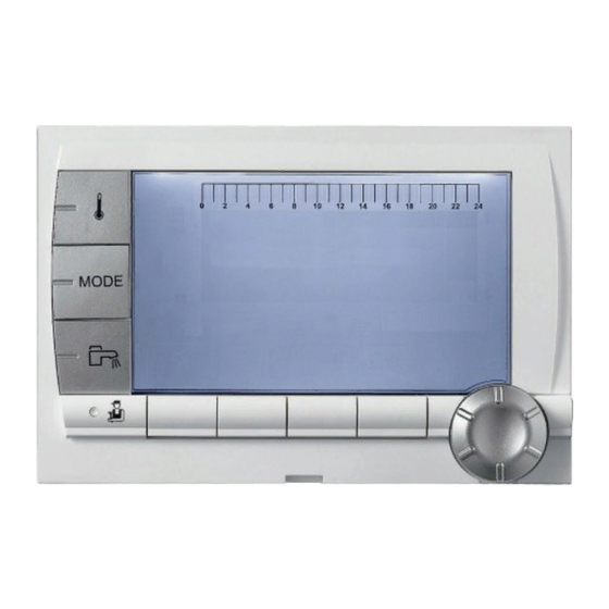
3. Technical description iSense Pro DIN - AD280 Technical description Description of the keys AUTO Temperature setting key (heating, DHW, swimming pool) Operating mode selection key DHW override key Key to access the parameters reserved for the installer Keys on which the function varies as and when selections are made Rotary setting button: Turn the rotary button to scroll through the menus or... -
Page 9: Description Of The Display
iSense Pro DIN - AD280 3. Technical description Description of the display 3.2.1. Key functions Access to the various menus > Used to scroll through the menus Used to scroll through the parameters The symbol is displayed when help is available Used to display the curve of the parameter selected <... -
Page 10: Operating Modes
3. Technical description iSense Pro DIN - AD280 3.2.4. Operating modes Summer mode: The heating is off. Domestic hot water continues to be produced WINTER mode: Heating and domestic hot water working < AUTO Operation in automatic mode according to the timer AUTO programme Comfort mode: The symbol is displayed when a DAY... -
Page 11: Other Information
iSense Pro DIN - AD280 3. Technical description 3.2.6. Other information The symbol is displayed when domestic hot water production is running. Valve indicator: The symbol is displayed when a 3-way valve is connected. x: 3-way valve opens < AUTO c: 3-way valve closes The symbol is displayed when the pump is operating. -
Page 12: Installation
4. Installation iSense Pro DIN - AD280 Installation Package list The delivery includes: 4 The iSense Pro DIN module 4 Electrical harness 4 Extension cable marked K1 (Useful depending on the control panels) 4 Outside sensor 4 Flow sensor (x2) 4 DHW sensor 4 Earth terminal block + 2 screws 4 Installation and Service Manual... -
Page 13: Connecting The Outside Sensor
iSense Pro DIN - AD280 4. Installation Recommended position Possible position Inhabited height controlled by the sensor Inhabited area controlled by the sensor 8800N001-C Positions to be avoided: 4 masked by a building element (balcony, roof, etc.) 4 close to a disruptive heat source (sun, chimney, ventilation grid, etc.) 8800N002-C 4.2.2. -
Page 14: Mounting And Connecting The Module
4. Installation iSense Pro DIN - AD280 Mounting and connecting the module 4.3.1. Boiler GAS 210 ECO PRO C003311-B C003312-B CAUTION Step 3: Connect the extension cable K1 between connectors A and Z. 22/11/2012 - 300025649-001-01... -
Page 15: Boiler Gas 310 Eco
iSense Pro DIN - AD280 4. Installation 4.3.2. Boiler GAS 310 ECO C003313-A C003314-B C003315-A 22/11/2012 - 300025649-001-01... - Page 16 4. Installation iSense Pro DIN - AD280 C003316-A C003317-C C003318-B 22/11/2012 - 300025649-001-01...
-
Page 17: Boiler Gas 310 Eco Pro
iSense Pro DIN - AD280 4. Installation C003319-B C003320-B 4.3.3. Boiler GAS 310 ECO PRO M002972-A 22/11/2012 - 300025649-001-01... - Page 18 4. Installation iSense Pro DIN - AD280 M002973-B M002974-B X3 X2 M002975-A 22/11/2012 - 300025649-001-01...
-
Page 19: Electrical Connections
iSense Pro DIN - AD280 4. Installation Electrical connections 4.4.1. Recommendations WARNING Only qualified professionnals may carry out electrical connections, always with the power off. The boiler is entirely pre-wired. Do not modify the connections inside the control panel. Earth the appliance before making any electrical connections. -
Page 20: Connecting The Bus Cable
4. Installation iSense Pro DIN - AD280 Not connected 0-10 V Inlet 0-10 Volts voice remote monitoring module - Package AD152 3 way valve circuit C Outside sensor - Package FM46 I AF Outside radio-controlled temperature sensor - Package AD251 3 way valve circuit B DHW sensor - Package AD212 r BF... -
Page 21: Connecting A Heating Circuit And A Domestic Hot Water Tank
iSense Pro DIN - AD280 4. Installation Outside sensor Boiler Earth the various pumps and 3-way valves. Settings to be made for this type of installation Parameters Access Settings to be made See chapter ¼ "Setting the heating curve", page 42 CIRC.CURVE B Installer level To be customised Menu #SECONDARY INSTAL.P... -
Page 22: Connecting Two Circuits And A Domestic Hot Water Tank
4. Installation iSense Pro DIN - AD280 D.H.W. load pump Earth the various pumps and 3-way valves. Settings to be made for this type of installation Parameters Access Settings to be made See chapter ¼ "Setting the heating curve", page 42 CIRC.CURVE B Installer level To be customised Menu #SECONDARY INSTAL.P... -
Page 23: Connecting A Direct Circuit, A Valve Circuit And A Dhw Tank
iSense Pro DIN - AD280 4. Installation Heating circuit C Earth the various pumps and 3-way valves. Settings to be made for this type of installation Parameters Access Settings to be made See chapter ¼ "Displaying the parameters in extended INSTALLATION Installer level EXTENDED Menu #SYSTEM... -
Page 24: Hot Water Storage Tank Connection
4. Installation iSense Pro DIN - AD280 Domestic circulation loop pump (Optional) D.H.W. load pump Heating pump circuit C Heating circuit C Earth the various pumps and 3-way valves. Settings to be made for this type of installation Parameters Access Settings to be made See chapter ¼... - Page 25 iSense Pro DIN - AD280 4. Installation S Syst. 0-10V N L N L N L N L C002818-C This type of installation only works if the boiler incorporates a boiler pump managed by the boiler regulator. Boiler regulator Connect the heating pump (Circuit B). DHW sensor Connect the sensor from the storage tank (Package AD250).
-
Page 26: Pool Connection
4. Installation iSense Pro DIN - AD280 The DHW part is maintained at the DHW set point by the boiler. The heating zone is maintained at the set temperature calculated according to the outside temperature. The zone is reheated when the heating buffer temperature sensor T falls -6°C below the calculated set temperature. - Page 27 iSense Pro DIN - AD280 4. Installation Settings to be made for this type of installation Parameters Access Settings to be made See chapter ¼ "Displaying the parameters Installer level INSTALLATION EXTENDED Menu #SYSTEM in extended mode", page 38 ¼ "Professional settings", Installer level Set the value of MAX.
-
Page 28: Connecting A Mixed Tank
4. Installation iSense Pro DIN - AD280 n Hourly programming of the secondary circuit pump The secondary pump operates during programme B comfort periods in summer and winter alike. n Stopping To prepare your pool for winter, consult your pool specialist. 4.4.10. - Page 29 iSense Pro DIN - AD280 4. Installation S Syst. 0-10V CDI CDR N L N L N L N L MODE TELCOM 2 MODE C002821-C Connect the load pump of the second tank. Second domestic hot water tank. Connect the DHW sensor of the second tank. Connect the TELCOM remote vocal monitoring module.
-
Page 30: Connection In Cascade
4. Installation iSense Pro DIN - AD280 4.4.12. Connection in cascade n DHW tank after the mixing tank C002822-B Master boiler Secondary boiler Secondary boiler D.H.W. load pump DHW sensor Cable BUS Low loss header Cascade outlet sensor Connect the sensor to the terminal block E.SYST on the master boiler. - Page 31 iSense Pro DIN - AD280 4. Installation Settings to be made for this type of installation: Follower boilers Parameters Access Settings to be made See chapter ¼ "Displaying the parameters in extended Installer level INSTALLATION EXTENDED Menu #SYSTEM mode", page 38 ¼...
- Page 32 4. Installation iSense Pro DIN - AD280 DHW storage tank Domestic circulation loop pump (Optional) Outside sensor (Optional) OTH Modbus interface board (Package AD286 / AD287) System sensor Connect a safety thermostat if the heating circuit is for underfloor heating. Settings to be made for this type of installation: iSense Pro DIN master module Parameters Access...
- Page 33 iSense Pro DIN - AD280 4. Installation Low loss header BUS cable to make the link between boilers 3 way valve circuit B Heating pump circuit B Outlet sensor circuit B Heating circuit B 3 way valve circuit C Heating pump circuit C Outlet sensor circuit C Heating circuit C D.H.W.
-
Page 34: Electrical Connection Diagram
4. Installation iSense Pro DIN - AD280 Electrical connection diagram C003959-A 22/11/2012 - 300025649-001-01... -
Page 35: Operating The Appliance
iSense Pro DIN - AD280 5. Operating the appliance Operating the appliance Powering up for the first time 1. The first time the boiler is powered up, the LANGUAGE menu is displayed. Select the desired language by turning the rotary button. -
Page 36: Installer Level
5. Operating the appliance iSense Pro DIN - AD280 5.2.2. Installer level The information and settings in the Installer level can be accessed by experienced people. 1. Press the > key. SUNDAY 11:45 < AUTO C002219-D-04 2. Press the - key. It is also possible to access the installer level by pressing SUNDAY 11:45 only the - key for around 5 seconds. -
Page 37: Browsing In The Menus
iSense Pro DIN - AD280 5. Operating the appliance Browsing in the menus 1. To select the desired menu, turn the rotary button. 2. To access the menu, press the rotary button. #MEASURES To go back to the previous display, press the key j . #CHOICE TIME PROG. -
Page 38: Reading Out Measured Values
5. Operating the appliance iSense Pro DIN - AD280 Reading out measured values The various values measured by the appliance are displayed in the #MEASURES menu. 1. To access user level: Press the > key. 2. Select the menu #MEASURES. SUNDAY 11:45 Turn the rotary button to scroll through the menus or modify a value. -
Page 39: Settings After Powering Up For The First Time
iSense Pro DIN - AD280 5. Operating the appliance Settings after powering up for the first time 5.5.1. Displaying the parameters in extended mode The display mode on the control panel is set as standard in such a way as only to show the conventional parameters. It is possible to switch to extended mode by proceeding as follows: 1. - Page 40 5. Operating the appliance iSense Pro DIN - AD280 Installer level - #SYSTEM menu Parameter Adjustment range Description Factory setting Customer setting Connecting a circuit with 3-way valve ( For CIRC. B: example: Underfloor heating) Using the circuit for pool management SWIM.P.
- Page 41 iSense Pro DIN - AD280 5. Operating the appliance Installer level - #SYSTEM menu Parameter Adjustment range Description Factory setting Customer setting Boiler anti-freeze activation (1)(4) ANTIFR ANTIFR I.TEL: ON or OFF contact: I.TEL: can be used as an 0/1 B antifreeze activation inlet on circuit B ON or OFF contact: I.TEL: can be used as an 0/1 C...
-
Page 42: Naming The Circuits And Generators
5. Operating the appliance iSense Pro DIN - AD280 Influence of the parameter setting CTC.I.SYST on the I.SYST contact CTC.I.SYST I.SYST I.SYST contact closed I.SYST contact open The antifreeze mode is active on all boiler circuits. The mode selected on the boiler is active. CLOSE ANTIFR The mode selected on the circuit is active. -
Page 43: Setting The Heating Curve
iSense Pro DIN - AD280 5. Operating the appliance 6. Choose the other characters in the same way. The input zone may contain up to 6 characters. To move from one character to another, turn the rotary button. To exit without modifications, press key h . 7. - Page 44 5. Operating the appliance iSense Pro DIN - AD280 4. To modify the value directly, turn the rotary button. To modify the value by displaying the curve, press key f . CIRC.CURVE B "Slope of the heatcurve of the circuit B" <...
-
Page 45: Changing The Settings
iSense Pro DIN - AD280 5. Operating the appliance Maximum temperature of the circuit C° Water temperature in the circuit for an outside temperature of 0°C DAY set point on the circuit Outside temperature for which the maximum water temperature in the circuit is reached Value of the heating curve Select the parameter CIRC. -
Page 46: Defining The Configuration Mode
5. Operating the appliance iSense Pro DIN - AD280 5.6.2. Defining the configuration mode 1. Access the installer level: Press key - for around 5 seconds. 2. Select the menu #SYSTEM. SUNDAY 11:45 Turn the rotary button to scroll through the menus or TEMP.: 68°... -
Page 47: Professional Settings
iSense Pro DIN - AD280 5. Operating the appliance User level - #SETTING menu Parameter Adjustment range Description Factory setting Customer setting 15 to 30 °C Used to set the outside temperature above 22 °C SUM/WIN which heating will be shut down. The heating pumps are shut down. - Page 48 5. Operating the appliance iSense Pro DIN - AD280 Installer level - #PRIMARY LIMITS menu Parameter Adjustment range Description Factory setting Customer setting 40 to 90 °C Maximum temperature authorised by the boiler 90 °C BOILER MAX 10 to 50 °C Minimum temperature authorised by the boiler 20 °C BOILER MIN...
- Page 49 iSense Pro DIN - AD280 5. Operating the appliance Installer level - #SECONDARY INSTAL.P menu Parameter Adjustment range Description Factory Customer setting setting 0 to 4 Heating curve of the circuit C CIRC.CURVE C ¼ "CIRC. CURVE ...", page 50 0.0 to 10.0 Activation and adjustment of the ANTICIP.C...
- Page 50 5. Operating the appliance iSense Pro DIN - AD280 Installer level - #SECONDARY INSTAL.P menu Parameter Adjustment range Description Factory Customer setting setting Automatic adaptation of the heating curves ADAPT for each circuit with a room sensor with an influence of >0. The heating curves can only be modified manually.
- Page 51 iSense Pro DIN - AD280 5. Operating the appliance n MAX.CIRC... WARNING If using underfloor heating, do not modify the factory setting (50 °C). To install this, please consult existing legislation. Connect a safety thermostat to the CS contact on the pump connector.
- Page 52 5. Operating the appliance iSense Pro DIN - AD280 The activation of this parameter (setting other than OFF) forces the permanent display of SCREED DRYING and deactivates all other functions on the control unit. When floor drying is active on a circuit, all other circuits (e.g. DHW) are shut down.
- Page 53 iSense Pro DIN - AD280 5. Operating the appliance 4 NIGHT :STOP (Stop): Heating is shut down during reduced periods. When installation antifreeze is active, the reduced temperature is maintained during reduced periods. For circuits with a room sensor: 4 When the room temperature is lower than the room sensor set point: The reduced temperature is maintained during reduced periods.
-
Page 54: Configuring The Network
5. Operating the appliance iSense Pro DIN - AD280 The quantity of heat (kWh value) can only be used for checks carried out for personal reasons. Flat solar panels Solar panel ) Number of Flow rate Flow rate Area (m installation panels (l/h) - Page 55 iSense Pro DIN - AD280 5. Operating the appliance Installer level - Menu #NETWORK Parameter Adjustment range Description Factory setting Customer setting Specific menu: Enlist VMs in cascade SYSTEM NETWORK mode ¼See chapter: "Connecting VM iSense Pro in cascade", page Operation in cascade: Successive CLASSIC CLASSIC...
- Page 56 5. Operating the appliance iSense Pro DIN - AD280 3. To add a slave appliance to the network, select ADD SLAVE. NB.NETWORK ELEMENTS ADD SLAVE ERASE NETWORK < AUTO C002410-C-04 4. The screen displayed allows you to choose numbers for the slave boilers to be added to the network.
-
Page 57: Return To The Factory Settings
iSense Pro DIN - AD280 5. Operating the appliance 4. The screen displayed is used to select the numbers of the slave VMs to be removed from the network. Turn the rotary button to scroll through the numbers and press to remove the number chosen. -
Page 58: Switching Off The Appliance
6. Switching off the appliance iSense Pro DIN - AD280 Switching off the appliance Installation shutdown CAUTION Do not switch off the mains supply to the appliance. If the central heating system is not used for a long period, we recommend activating the HOLIDAYS mode (to ensure the anti-grip of the heating pump). -
Page 59: Troubleshooting
iSense Pro DIN - AD280 7. Troubleshooting Troubleshooting Installer’s contact details To display the installer’s telephone number when an error is displayed, proceed as follows: 1. Access the "After Sales" level: Hold key - down until #PARAMETERS is displayed. 2. Select the menu #SUPPORT. SUNDAY 11:45 TEMP.: _ _ _ _ Turn the rotary button to scroll through the menus or... -
Page 60: Message History
7. Troubleshooting iSense Pro DIN - AD280 Code Messages Description Checking / solution The shutdown is active A shutdown is underway. The circuits selected for this stop STOP N XX XX = Number of the active are in Antifreeze mode during the period chosen. shutdown Wait until the end date has been passed Set the parameter STOP N XX to OFF... -
Page 61: Faults
iSense Pro DIN - AD280 7. Troubleshooting Faults If a malfunction occurs, the module flashes and displays an error message and a corresponding code. 1. Make a note of the code displayed. The code is important for the correct and rapid diagnosis of the type of failure and for any technical assistance that may be SUNDAY 11:45 needed. - Page 62 7. Troubleshooting iSense Pro DIN - AD280 Code Faults Description Checking / solution Domestic hot water sensor fault Bad connection DHW S.FAILURE Remarks: ¼See Check whether the sensor is connected: Domestic hot water heating is no chapter: "Deletion of sensors from the memory in longer controlled.
-
Page 63: Deletion Of Sensors From The Memory In The Pcb
iSense Pro DIN - AD280 7. Troubleshooting Code Faults Description Checking / solution Solar tank sensor fault Bad connection ST.TANK S.FAIL ¼See Check whether the sensor is connected: chapter: "Deletion of sensors from the memory in the PCB", page 62 Check the link and the connectors Check that the sensor has been correctly fitted Sensor fault... -
Page 64: Failure History
7. Troubleshooting iSense Pro DIN - AD280 Failure history The menu #DEFAULT HISTORIC is used to consult the last 10 faults displayed by the control panel. 1. Access the "After Sales" level: Hold down the - key until #PARAMETERS is displayed. 2. - Page 65 iSense Pro DIN - AD280 7. Troubleshooting After Sales level - #PARAMETERS menu Parameter Description Master boiler active PERMUT Number of boilers requesting heating STAGE Number of boilers recognised in the cascade NB.CASC.: Number of VM iSense Pro control systems recognised in the cascade NB.
- Page 66 7. Troubleshooting iSense Pro DIN - AD280 After Sales level - #TEST INPUTS menu Parameter Status Description Status of the telephone inlet 0 / 1 PHONE REM. Status of the telephone inlet 0 / 1 I.SYST Presence of a remote control B R.CTRL B No remote control B Presence of a remote control C...
-
Page 67: Spare Parts
iSense Pro DIN - AD280 8. Spare parts Spare parts General When it is observed subsequent to inspection or maintenance work that a component in the appliance needs to be replaced, use only original spare parts or recommended spare parts and equipment. Send the component to be replaced to your supplier’s Returned Goods Department if the component in queston is under warranty (see general terms and conditions of sale and delivery). -
Page 68: Spare Parts
8. Spare parts iSense Pro DIN - AD280 Spare parts Markers Code no. Description 95362449 Outlet sensor 95362450 Outside sensor 97385252 Syringe 95362448 KVT sensor 60 l. 5 m 300026400 Complete electrical harness 300026401 Adaptation electrical harness 300026419 Connection to the earth terminal block 200016858 Flat cable 300029233 iSense Pro DIN regulator S101249... - Page 69 iSense Pro DIN - AD280 8. Spare parts 22/11/2012 - 300025649-001-01...
- Page 72 Broag Ltd. Remeha House Molly Millars Lane RG41 2QP WOKINGHAM, Berks. Tel: +44 118 9783434 Fax: +44 118 9786977 Internet: uk.remeha.com E-mail: boilers@broag-remeha.com © Copyright All technical and technological information contained in these technical instructions, as well as any drawings and technical descriptions supplied, remain our property and shall not be multiplied without our prior consent in writing.
Need help?
Do you have a question about the iSense Pro DIN AD280 and is the answer not in the manual?
Questions and answers