
Related Manuals for Fly Sky FS-i4X


Summary of Contents for Fly Sky FS-i4X
- Page 1 Digital proportional radio control system INSTRUCTION MANUAL Digital proportional radio control system WARNING: Copyright ©2013-2017 This product is only for 15 years old or above Flysky RC model technology co., ltd...
- Page 2 Thank you for purchasing our product, an ideal radio system for beginners or experienced users alike. Read this manual carefully before operation in order to ensure your safety, and the safety of others or the safe operation of your system. If you encounter any problem during use, refer to this manual first.
-
Page 3: Table Of Contents
5.3 V-Mix ..................................15 6. System Customization ........................16 6.1 Switching Channel Asignments ........................16 7. Customization Selection Sheet .....................20 8. Package Contents ...........................21 9. Product Specification ........................22 9.1 Transmitter Specification (FS-i4X) ......................22 9.2 Receiver Specification (FS-A6) ........................22 Appendix 1 FCC Statement ......................23... - Page 4 This page is intentionally left blank.
-
Page 5: Safety
Digital proportional radio control system 1. Safety 1.1 Safety Symbols Pay close attention to the following symbols and their meanings. Failure to follow these warnings could cause damage, injury or death. Danger • Not following these instructions may lead to serious injuries or death. Warning •... - Page 6 • Misuse of this product may lead to serious injury or death. To ensure the safety of you and your equipment, read this manual and follow the instructions. • Make sure the product is properly installed in your model. Failure to do so may result in serious injury.
-
Page 7: Introduction
Digital proportional radio control system 2. Introduction The FS-i4X transmitter and FS-A6 receiver constitute a 4-channel 2.4GHz AFHDS 2A digital proportional computerized R/C system. It is compatible with fixed-wing and helicopters. 2.1 System Features The AFHDS 2A (Automatic Frequency Hopping Digital System Second Generation) developed and patented by FLYSKY is specially developed for all radio control models. -
Page 8: Transmitter Overview
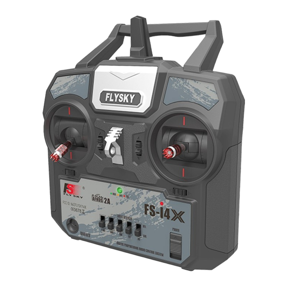
2.2 Transmitter Overview Antenna Handle Lanyard Hook Right Gimbal Left Gimbal Trim 3 Trim 1 Trim 2 Trim 4 Bind Button Power Switch V-MIX Reverse Switches Trainer Port Battery Compartment... -
Page 9: Transmitter Antenna
Digital proportional radio control system 2.2.1 Transmitter Antenna Precautions: • For best signal quality, make sure that the antenna is at about a 90 degree angle to the model. Do not point the antenna directly at the receiver. • Never grip the transmitter antenna during operation. It significantly degrades the RF signal quality and strength and may cause loss of control. -
Page 10: Connectors
2.3.3 Connectors The connectors are used to connect the parts of model and the receiver. • CH1 to CH6: used to connect the servos, power or other parts. • BAT: used to connect the bind cable for binding, and the power cable during normal operation. To Battery Rudder Switch... -
Page 11: Getting Started
Digital proportional radio control system 3. Getting Started Before operation, install the battery and connect the system as instructed below. 3.1 Transmitter Battery Installation Danger • Only use specified battery. Danger • Do not open, disassemble, or attempt to repair the battery. Danger •... -
Page 12: Operation Instructions
4. Operation Instructions After setting up, follow the instructions below to operate the system. 4.1 Power On Follow the steps below to turn on the system: Check the system and make sure that: • The batteries are fully charged and installed properly. •... -
Page 13: Binding
Digital proportional radio control system 4.3 Binding The transmitter and receiver have been pre-bound before delivery. If you are using another transmitter or receiver, follow the steps below to bind the transmitter and receiver: Connect the supplied bind cable to the BAT port on the receiver. Insert power into any other port. -
Page 14: Power Off
Switch the gimbals to the opposite side. Make sure the gimbals have been rotated 180 degrees so that the wires are facing towards the middle of the system. Move hat of the S16 connector so that one side is on the L or R pin, L for when the self centring stick is on the left side and R for when its on the right. -
Page 15: Function Descriptions
Digital proportional radio control system 5. Function Descriptions 5.1 Flight Controls (Default Mode 2) The sticks are used for controlling the aircraft, each stick has 2 functions. The right stick controls pitch and roll, the left stick controls throttle and yaw. Pitch (Right Stick Up/Down) DOWN Roll (Right Stick Left/Right) -
Page 16: Reverse Function
Throttle (Right Stick Up/Down) THROTTLE UP THROTTLE DOWN 5.2 Reverse Function Channels 1-4 can be reversed, to reverse a channel: • 1. Test the servo/throttle to make sure that the action corresponds as expected with the transmitters controls. • 2. If the direction of travel is wrong then toggle corresponding switch located at the bottom of the transmitter, labled as RUD (Rudder), THR (Throttle), ELE (Elevator), AIL (Aileron). -
Page 17: System Customization
Digital proportional radio control system 6. System Customization The FS-i4X's switches and knobs can be moved to other channels. Or if using receivers with more channels, the system can be expanded with extra switches or knobs. By default, from left to right, the switches and knobs are channels 5, 6, 7, 8, 9 and 10. - Page 18 • 5. Carefully remove the screws marked below in red. Note: Make sure you keep the screws in a safe place. • 6. Remove the power button cover from the front side of the system. To do so simply put the end of a screw driver under and and gently lift it off.
- Page 19 Digital proportional radio control system • 8. The connectors for channels 5 - 10 are marked in red on the diagram . On the circuit board each channel is labled, making it easy to find the correct channel. Follow the cables leading from each connector to identify which switch or knob goes to each channel.
- Page 20 Adding a knob: • 1. Using a flathead screwdriver carefully release the clips holding the plate on the front. The clips are marked in red in the picture . • 2. Carefull remove the cover plate and replace it with the new coverplate designed to hold 2 knobs.
-
Page 21: Customization Selection Sheet
Digital proportional radio control system 7. Customization Selection Sheet Addition Option 1 Option 2 Option 3 Left Side Switch 1 No Switch 2 Way Switch 3 Way Switch Long Long Option 4 Short Short Left Side Switch 2 No Switch 2 Way Switch 3 Way Switch Knob... -
Page 22: Package Contents
8.Package Contents 4-10 Channel 2.4GHz Transmitter (FS-i4X) 2.4GHz Receiver (FS-iA10B (10 CH) or FS-iA6B (6 CH) or FS-A6 (6 CH)) User Manual PS/2 to USB Update Cable... -
Page 23: Product Specification
Digital proportional radio control system 9. Product Specification 9.1 Transmitter Specification (FS-i4X) Channels 4 - 10 (Default 4) Model type Fixed-Wing/Glider/Helicopter RF range 2.4055-2.475GHz Bandwidth 500 KHz Band RF power Less then 20 dBm 2.4G system AFHDS 2A and AFHDS... -
Page 24: Appendix 1 Fcc Statement
Appendix 1 FCC Statement This equipment has been tested and found to comply with the limits for a Class B digital device pursuant to part 15 of theFCC rules. These limits are designed to provide reasonable protection against harmful interference in a residential installation. This equipment generates, uses and can radiate radio frequency energy and, if not installed and used in accordance with the instructions, may cause harmful interference to radio communications. - Page 25 Digital proportional radio control system http://www.flysky-cn.com Copyright ©2013-2017 Flysky RC model technology co., ltd Edition: 2015-9-1...
Need help?
Do you have a question about the FS-i4X and is the answer not in the manual?
Questions and answers
safe switch