
Related Manuals for Fly Sky FS-IT4


Summary of Contents for Fly Sky FS-IT4
- Page 1 Digital propotional radio control system 用户手册 http://www.flysky-cn.com Copyright ©2008-2012 Flysky co., ltd This product is suitable for 15 years old and above 本产品不适合15岁以下儿童使用...
-
Page 2: Table Of Contents
Digital propotional radio control system Table of contents 目录 1,Introduction 简介………………….…………………………………………..…..……………..2 2,Ser vices 服务………………………… …………………………………………………………..2 3,Special symbols 特殊标志………………………………………………………………...……..3 4,Safety guide 安全指导…………………………………………………………………..………..3 5,2.4GHz System 2.4G系统……………………………………………………………….………..6 6,Batter y charging notes 电池充电注意事项…………….……………………………..………7 7,Transmitter specifications 发射机参数……………………………………………..…………8 8, Receiver specifications 接收机参数…………………………………………………...………8 8.01,Speed acquisition module 磁感应速度采集模块……………………………….… 9 8.02,Speed acquisition module 光感应速度采集模块…………………………………. -
Page 3: 1,Introduction 简介
Introduction 简介 Thank you for choosing the Fly Sky FS-iT4 4 channels 2.4GHz AFHDS 2 computerized digitalproportional R/C car and boat system. If it’s your first use of a computerized radio system, this user manual will bring you easily to a new world of fun and sophistication. In all cases, please read carefully and completely this user manual as it contains all information to keep you safe. -
Page 4: 3,Special Symbols 特殊标志
Digital propotional radio control system Special symbols 特殊标志 Please pay attention to the following symbols when they appear in the manual and read carefully. 当以下标志出现在说明书的时候请注意并且仔细阅读。 Not following these instructions may expose the user to serious injuries or death. 如果使用者不按照说明方法操作,有可能导致使用者严重受伤,甚至致命的危险。 Not following these instructions may expose the user to serious injuries. - Page 5 Be sure to set the Fail Safe function. 一定要启用防失控功能. Do not operate outdoors on rainy days, run through puddles of water or use when visibility is limited. Should any type of moisture (water or snow) enter any component of the system, erratic operation and loss of control may occur.
- Page 6 Digital propotional radio control system Fail safe function Before running (cruising), check the fail safe function. Check Method; Before starting the engine, check the fail safe function as follows: (1) Turn on the transmitter and receiver power switches. (2) Wait at least 30 seconds, then turn off the transmitter. (The transmitter automatically transfers the fail safe data to the receiver every 5 seconds.) (3) Check if the fail safe function moves the servos to the preset position when reception fails.
-
Page 7: 5,2.4Ghz System 2.4G系统
2.4GHz System 2.4G系统 Misuse of this radio system can lead to serious injuries or death. Please read completely this manual and only operate your radio system according to it. 警告! AFHDS2 ( automatic frequency hopping digital system , is developed by FLYSKY for all the Radio Control 错误使用遥控设备将可能导致严重的伤害甚至... -
Page 8: 6,Batter Y Charging Notes 电池充电注意事项
Digital propotional radio control system System Characteristic 系统特征 This radio system works in the frequency range of 2.4000 to 2.4835GHz. This band has been divided into 160 independent channels. Each radio system uses 16 different channels and 160 different types of hopping algorithm. By using various switch-on times, hopping scheme and channel frequencies, the system can guarantee a jamming free radio transmission. -
Page 9: 7,Transmitter Specifications 发射机参数
Transmitter specifications 发射机参数 Transmitter specifications: Channels: 4 Model type: car/boat RF range: 2.4-2.48GHz Bandwidth: 500KHz MODEL: Band: 160 RF power: less than 20 dBm 2.4G system: AFHDS 2 Code type: GFSK Sensitivity: 1024 Low voltage warning: yes(less than 3.7V) DSC port: yes(USB HID) ST range: 90 TH range: 45(F: 30;B:15) Charger port: yes... -
Page 10: Speed Acquisition Module 磁感应速度采集模块
Digital propotional radio control system 8.01. Speed acquisition module 磁感应速度采集模块 机种参数: SPECIFICATIONS: 适合机种: 车、船 Model type: car/boat MODEL: FS-SPD01 采集速度范围: 0-16000转/分钟 Monitor range of speed16000RPM Power: 4.0-6.5V DC 机身重量: 10克 Weight: 10g 输入电源: 4.0-6.5V DC Size: 24.4*14*8mm 外形尺寸: 24.4*14*8毫米 Color: black 外观颜色:... -
Page 11: 9,Receiver And Ser Vo Connections 接收机与伺服器连接
9.Receiver and servo connections 接收机与伺服器连接 9.01. Installation when a motor controller is used: 带马达模型的安装连接 Remark: to guarantee a long range, place the antenna of the receiver vertically away from any metal part. 注意: 为保证良好的遥控距离,请将接收机天线与模型机身垂直放 置并远离金属物体。 9.02. Installation for gas powered models: 发动机模型的安装... -
Page 12: 10,Fs-Ir4 Operation Instruction Fs-Ir4接收机操作说明
Digital propotional radio control system FS-iR4 operation instruction FS-iR4接收机操作说明 port instruction 接口说明 CH1-CH4: 表示接收机的相应通道; BIND,VCC: 表示用于对码和输入电源的通道; OUT:表示输出PPM数据的 接口,用于连接串行 总线接收机,扩展通道; IN:表示各种传感器数据的输入接口,数据采集模块可 随意串接; CH1-CH4 represent relevant channel of transmitter. BIND,VCC represent the channel used for matching and input power respectively. OUT: represent ASbus port of outputting PPMS data and be used for connecting the serial bus receiver to expand channels. - Page 13 FS-SEV01 serial bus receiver connection instruction 串行总线接收机连接说明 串行总线接收机,最多可串联4个模块,共18个通道;按键K1-K4分别对应C1-C4,用于对相应通道的设定; 操作说明: 1、FS-SEV01接收机的“IN”端口对应接收机的“OUT”端口; 2、FS-SEV01接收机的“OUT”端口,用于串接后级的FS-SEV01接收机,以串 联的方式使用。 发射机 3、将此总线接收机插入接收机,打开己配对的 ,接收机电源,LED点亮; 发射机 4、操作 触控屏,选择接收机设定的主菜单,进入到舵机设定界面; 5、选择需要扩展的通道,此时,总线接收机的LED熄灭; 6、用对码线上的胶针,按下需要的,相应通道的按键,LED自动点亮,表示设定 成功; 7、插入舵机,检查设定是否成功; 8、重复以上操作即可完成总线接收机4个通道的设定; 9、当需要更多的通道扩展时,只需要在第一级总线接收机的“OUT”端口,串接 新的总线接收机即可,设定的操作方法相同。 注意:当总线接收机的负载过重,电流较大时,请将主接收机的电源分支出来并联接入,单独供电加大负载的能力, 否则可能会因电流过大,烧坏串联的线材。 Serial bus receiver can connect 4 modules with 18 channels in serial at most. Button K1 and K2 correspond to C1 and C2 respectively.
- Page 14 Digital propotional radio control system 采集模块的操作使用说明: FS-SPD02:光感应转速采集模块 操作使用说明: 1、将所配的3PIN插头,一端插入速度采集模块的“OUT”位置,另一端插入 接收机的“IN”位置或接另外的感应器的“IN”位置,如上图所示; 2、将图2所示,传感器与反射贴纸固定在轮子的侧面平面上,保持贴纸平整,并与传感器垂直; (备注:贴纸与轮子的颜色反差要大)传感器和贴纸距离要保持适中。 3、打开发射机,接收机电源,在显示屏的接收机窗口内,会发现并显示“Motor speed 2:0RPM”,试着转动轮子, 转速的值会发生变化,则表示安装成功。 备注: 也可安装在模型车的从动齿轮上,采用相同的方法采集齿轮的转速. 轮子 反射区 传感器 Cai wheel Magnet Sensor Telemetry module FS-SPD02: optical rotation speed telemetry module Operation: 1. Connect one end of the standard 3 PIN plug to the "out" port of the speed telemetry module and the other end to the "in"...
- Page 15 FS-SVT01:外部电压采集模块连接 操作使用说明: 1、将所配的3PIN连接线,一端插入电压采集模块的“OUT”位置,另一端插入接收机 的“IN”位置或接另外的感应器的“IN”位置; 2、打开 发射机 ,接收机电源,在显示屏的接收机窗口内,会发现并显示 “Ext.voltage4:0V”,表示安装成功; 3、将用于检测的红黑线插针分别插入电池的插头内,红色线为正极,黑色线为负极, 如图所示;在显示屏的接收机窗口内,显示“Ext.voltage4:12.40V”,表示己检测 到外部的电池电压为:12.40V。 注意:用于检测的红黑线,不能接反,否则会损坏接收机。 FS-SVT01: External voltage connection telemetry Operation instruction: 1. Insert one end of standard 3 PIN plug into “OUT” port of external voltage module, and insert the other end into “IN”...
-
Page 16: 11,Power On 开机
Digital propotional radio control system Power on 开机 1. Connnect all parts 1. 连接好所有部件 2. Switch on the transmitter 2. 打开发射机 3. Connect the receiver battery 3. 接通接收机电源 4. The receiver red LED indicator is solid 4. 接收机红色指示灯常亮说明信号连接正常. indicating the presence of a correct signal When the error rate of transmitter is less than 5%, 5.发射机的误码率小于5%,接收信号强度稳定(TX/RX电量... -
Page 17: 13,Definition Of Key Functions 按键定义
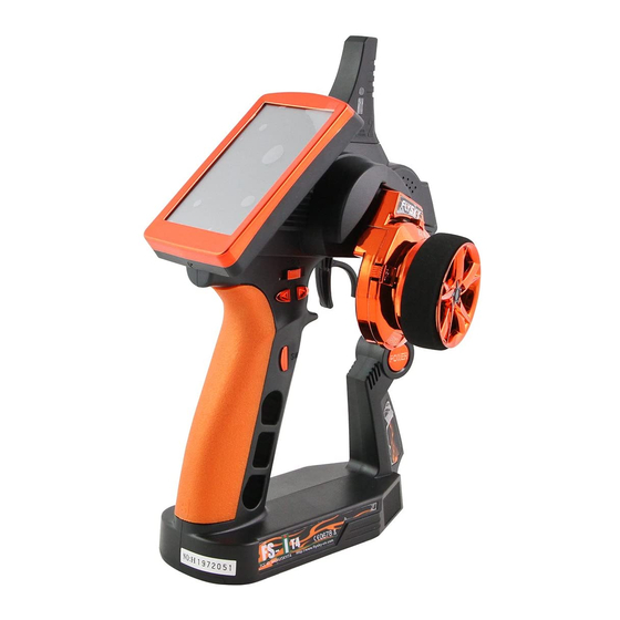
Definition of key functions 按键定义 2.4G ANT Stylus Steering wheel Power Micro USB Throttle Trigger http://www.flysky-cn.com... -
Page 18: 14,Main Screen 开机画面
Digital propotional radio control system 开机画面 Main screen 开机画面显示了富斯公司的标志, 两秒后进入到主菜单. 主菜单显示的具体内容如下图 The screen display the logo of FLYSKY. Entering the main menu after two seconds . the main menu is as the following picture: 模型名称 Model name Transmitter battery 发射机电池状态 接收信号... -
Page 19: 15,Main Menu 主菜单
主菜单 Main menu Main menu page 1 Main menu page 2 主菜单第一页 主菜单第二页 The main menu can be accessed by touching the settings 点触屏幕下方的设置图标 进入主菜单。 icon at the bottom of the main screen. The main menu is organized in horizontal pages. Each 主菜单有两个平行页面组成,每个页面包含最多12个图标,... -
Page 20: 17,Functions Interface 功能操作
Digital propotional radio control system Functions interface 功能操作 All functions use a set of standard user interface objects. The bottom tray can contain the following buttons: 所有的功能使用一套标准的用户界面对象。 屏幕底部包含以下图标: The back buttons returns to the previous screen 返回图标用于返回上一页面 The default button sets back the current page parameters to their default values. 默认图标可将当前页参数恢复到默认值。... - Page 21 Some menus are a set of radio buttons that will modify a multi-value parameter. The blue ball indicates the currently selected value. To select another value, simply touch it. 由一套单选按键组成的菜单可以选择多值参数配置。 蓝色球体代表当前选择的选项,如需选择其它的 选项 ,只需点击该 选项 。 Some menu items embed a check box. To toggle a check box, simply touch it.
-
Page 22: Reverse 正逆转
Digital propotional radio control system Reverse 正逆转 17.01: The reverse function individually reverses the direction of operation of the servos on the 4 channels. This dialog box contains 4 big check boxes, one for each channel. To toggle the reverse state of a channel, just touch it. In this example, only the third channel is reversed, the other channels operate normally. -
Page 23: Sub Trims 记忆微调
Sub trims 记忆微调 17.03: The sub trims function individually adjusts the center position of each servo of the 4 channels. This is particularly useful when the servo mechanics doesn’t allow an adjustment fine enough. Touch the channel which sub trim must me adjusted Use the wheel to move the red needle and modify the sub trim value of the selected channel. -
Page 24: Steering Speed 方向速度
Digital propotional radio control system Steering speed 方向速度 17.05: If the steering servo throws too fast to an extreme position or returns too fast to its neutral position, it may result in a loss of control of the vehicle. The steering speed function limits the maximum angular speed of the steering servo. 2 buttons select which speed to limit. -
Page 25: Throttle Neutral 油门死区
Throttle neutral 油门死区 17.07: The throttle neutral function defines the behavior of the throttle near its neutral position. 3 buttons select which parameter to adjust. Dead zone: defines the width of a zone around the neutral position of the throttle trigger where the trigger will have no effect and will be read as neutral. -
Page 26: Throttle Curve 油门曲线
Digital propotional radio control system Throttle curve 油门曲线 17.09: The throttle curve defines a 5 points broken-line transfer curve between the throttle trigger and the throttle servo. 5 buttons select one on the 5 points to adjust. Each point can be independently adjusted from 0% (full brake) to 100% (full throttle). -
Page 27: A.b.s. 自动刹车
17.10: A.B.S. 自动刹车 The automatic brake system (A.B.S.) pulses the brakes to avoid blocking the wheels and losing control of the vehicle. A first menu selects which one of the 6 parameters to modify. Brake return: determines how much the brakes will be released at each pulse. 100% completely releases the brakes and the servo returns to its neutral position at each pulse. -
Page 28: Throttle Speed 油门速度
Digital propotional radio control system Throttle speed 油门速度 17.11: The throttle speed is identical to the steering speed but applies to the channel 2. The throttle go speed can be assigned to a trim switch. The throttle return speed can be assigned to a trim switch. 油门速度同方向速度相同,但仅适用于2通道。... -
Page 29: Engine Cut 油门锁定
Engine cut 油门锁定 17.14: When activated, the engine cut ignores the throttle trigger position and set the throttle to a predefined position. It can be used to turn of the ignition of a gas powered vehicle. In this example, the throttle trigger is at full throttle but since the engine cut function is activated and set to -90%, the throttle servo brakes slightly. -
Page 30: Mixes 混控
Digital propotional radio control system 17.17: Mixes 混控 4 independent mixes can be applied between any master and slave channel. Each mix, when activated, will let the slave channel be influenced by its master channel. A fraction of the master channel, eventually negative, is added to the slave channel. Furthermore, the slave channel can be shifted up or down by a given value. -
Page 31: Display Servos 显示舵机
Display servos 显示舵机 17.18: This function displays in real time the position of the 4 servos. The test button let the 4 servos to move slowly between their respective end points. This allows to test the consistency of the mechanics of the model. 此功能显示4个舵机的即时位置。... -
Page 32: Race Timer 计时器
Digital propotional radio control system Lap timer: the lap timer is an up timer. Once started, the start button becomes the lap button. Each time the lap button is touched, the time elapsed since the last lap or the timer start is displayed for 3 seconds and recorded in the lap memory. -
Page 33: Models 模型
This is the beginning of the This is the beginning of trim switch functions list the push button functions menu. list menu. 此图显示的是微调开 关功能菜单的上面 此图显示的是按钮菜 单功能的上面 17.21: Models 模型 20 model configurations can be independently saved and managed allowing to instantly switch between 20 different vehicles to control. - Page 34 Digital propotional radio control system Copy model: The second menu selects the copies a model configuration target model configuration to to another. The target copy to. configuration is lost and replaced by the source 第二个菜单选择需要复制 configuration. 的目标模型数据。 The first menu selects the source model configuration to copy from.
-
Page 35: Rx Setup 接收设置
17.22: RX setup 接收设置 Set up the receiver. RX setup menu are like the picture 1. Bind with a receiver: the transmitter enters in bind mode. Once the receiver correctly bound, press the back button to return to normal operation.( picture 3 RX battery monitor: monitors the receiver battery voltage.(... - Page 36 Digital propotional radio control system Display sensors: Servos setup: display the type, ID and value if servos are connected on of all connected sensors. the external serial interface, receiver can connect 15 this function attributes a sensors at most. channel to each servo. Choose the channel to 传感器列表:...
- Page 37 RX setup 接收设置 17.22: 速度与距离 若转速传感器与接收机连接,该功能可设置虚拟速度和里 程表传感器,如图1所示. 传速传感器 选择转速传感器.如果没有选择,该功能将被禁用. 每圈长度 设置旋转一圈车辆的行程.该距离用于计算虚拟速度和里程 表传感器. 点击“每圈长度”,设置模型车每圈的能走的距离 (单位:毫米),点击返回即可,如图2所示。 Speed and distance: As shown in picture 1, if a rotation speed sensor is connected to the receiver, this function set up the virtual speed and odometers sensors. Speed sensor: Select the rotation speed sensor to use.
-
Page 38: System 系统
Digital propotional radio control system 17.23: System 系统 声音: The system menu sets various system wide 开启或关闭发射机声音 parameters 自动关机 开启此功能后,若当五分钟 系统菜单设置不同的系统 内没有操作发射机时,发射 范围的参数。 机将自动报警,报警时间会 持续五分钟,然后机器将自 动关闭。 报警的同时LED会闪烁指示, 点击“自动关机”可取消自 动关机功能。 Sound: Turn on or turn off the sound of the transmitter. Auto power off: After five minutes of no operation, the transmitter... - Page 39 “system”-----“USB function”------“FS-IT4 simulator”. After that, the computer will automatic identify the HID. 3. In the computer control panel, double click “ game controller ” --------“FS-IT4 emulator” to test whether the simulating function is ok. About FS-iT4 Touch 'About FS-iT4',and USB功能...
-
Page 40: 18,Transemitter Function Notes 发射机功能说明
Digital propotional radio control system Transmitter function notes 发射机功能说明 18. 01 Steering control: 方向控制 Function explanation: This function is to control the direction,When the steering turn to right then the front wheel will t urn to right (see the picture),When the steering turn to left then the front wheel will turn to left (see the picture). - Page 41 报警功能说明 18.03: alarm function description 声音报警 1,发射机电量不足,电压低于3.75V时,系统发出慢的警报声响。 2,接收机电量不足,低于设定的报警电压时,系统发出“叭,叭”声响。 3,误码率超过60%时,系统发出“嘟,嘟”声响。 4,计时到达时,系统发出闹铃“Bi,Bi,Bi,Bi”声响三次。 5,自动关机报警时,系统发出“嘟,嘟,嘟”的声响。 6,发射机电量严重不足,电压低于3.7V时,系统发出快的警报声响,当电压低于3.65V时,发射机将自动关机。 Audible alarm 1. When the transmitter battery is low and the voltage is lower than 3.75 V, the system will make alarm which sounds slowly. 2. If the voltage is lower than setting data due to low battery of receiver, the system will make a sound "Ba,Ba". 3.
- Page 42 Digital propotional radio control system 18.03: Problem solving 常见故障说明 常见故障说明 1,发射机不能开机 电池安装不到位 电池电量不足 开机时屏幕会闪一下,然后又关闭.表示电量不能维持系统长时间开机,开机瞬间就马上关闭 电池弹片氧化,接触不良 2,遥控距离不够 发射机或接收机天线摆放位置不对 附近有无线电干扰 电池电量不足 有障碍物遮挡,屏蔽掉部分信号 3,发射机不能遥控接收机 发射机或接收机误进入对码状态,重开机即可,必要时需重新对码 4,多人同时比赛时,发射机有时收不到接收机反馈回来的数据 两台发射机间的距离太近,尽可能保持5米以上, 5,发射机屏幕内不显示采集模块的编号 采集模块的数据线插错位置 数据线插头松脱,破损,断线 6,转速采集的数据不稳定 转速传感器位置摆放不当,偏离太远 7,电脑找不到模拟器 发射机USB模拟器没有打开 Problem solving 1.Transmitter does not start up The battery is not properly installed. Battery is empty The screen flashes when the transmitter is powered on, and then the transmitter turn itself off immediately.
-
Page 43: 19,Packaging Content 包装内容
Packaging content 包装内容 Model Sum Remarks Model Sum Remarks 4 channel 2.4G transmitter (FS-iT4) FS-SEV01 4 通2.4G发射机 可选的 串行总线接收机 ASBUS 4 channel 2.4G FS-SPD01 receiver (FS-iR4) 磁感应转速采集模块 4 通2.4G接收机 magnetic telemetry 可选的 sensor FS-SPD02 光感应转速采集模块 FS-BA1200 optical telemetry 可选的 锂电池... -
Page 44: 20,Fcc Statement Fcc声明
Digital propotional radio control system FCC Statement 声明 FCC Statement This equipment has been tested and found to comply with the limits for a Class B digital device pursuant to part 15 of the FCC rules. These limits are designed to provide reasonable protection against harmful interference in a residential installation. - Page 45 http://www.flysky-cn.com copy right 2008 @flysky co.,ltd...
Need help?
Do you have a question about the FS-IT4 and is the answer not in the manual?
Questions and answers