Table of Contents
Advertisement
Advertisement
Table of Contents

Related Manuals for CAME PST001


Summary of Contents for CAME PST001
- Page 1 TRIPOD 1 19 G304 0EN TURNSTILE INSTALLATION MANUAL PST001 English...
-
Page 2: Read Carefully
Warning Sings (e.g. gate plate). (i.e. that for which it was expressly built for). Any other use is Special instructions and to be considered dangerous. Came Cancelli Automatici S.p.A. advice for users is not liable for any damage resulting from improper, wrongful •... - Page 3 THIS PAGE LEFT INTENTIONALLY BLANK THIS PAGE LEFT INTENTIONALLY BLANK...
-
Page 4: Legend Of Symbols
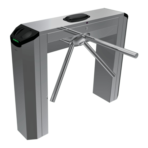
4.1 Turnstile This product is designed and built by CAME Cancelli Automatici S.p.A. in compliance with the current safety legislation. It allows passage in the desired direction of one person a time. By activating a command device, the mechanism releases the tripod which rotates freely allowing people to pass through;... - Page 5 4.3 Description of parts Legs Tripod Steel body Casing Casing cover Upper cover Traffic-light with display Transponder Status display Mechanism Control panel Cover lock Screws and washers for fixing the legs Screws for fixing the casing 4.4 Dimensions 1200...
-
Page 6: Application Examples
5 Application examples Warning: Turnstile-controlled exits cannot serve as emergency exits. Always have an emergency exit and one also for disabled persons. Standard installation Against the wall installation Multiple installation Platform installation Suggested distance between turnstiles 6 Installation Only skilled, qualified staff must perform the installation, in full compliance of the current legislation. 6.1 Preliminary checks Before installing the automated device, please: •... - Page 7 6.3 Standar installation Tripod turnstile Traffi c-light with display Electric wiring connector block Transponder for transit access Protection handrail Status displays 6.4 Setting up the turnstile Warning: installation required two people. Use hoisting equipment to move and position the turnstile. Do not lean on the turnstile until it is solidly anchored, to prevent it from toppling over.
- Page 8 4) Remove the top cover. Note: Lift the cover slightly tor easy removal. 5) Remove the two screws that fix the casing to the legs. 6) Remove the protective casings by gently lifting them. Then, extract the casings. 6) Use the supplied M10 x 60 screws and flat washer to secure the three arms to the tripod hub.
- Page 9 6.5 Preparing the site and fixing the turnstile to the ground. 1) Check that the floor where the turnstile is anchored is level 2) Depending on the size of the passage, decide where to and without warping. install the turnstile and any accessories that should be added, marking the fixing holes with a pencil respecting the measure- ments given in the drawing.
- Page 10 7 Electric cabling Use the proper cable clamps to secure Pass the cable through the hole in the the cables inside the box in the control top of the turnstile leg. panel. Cable clamps Hole Earth Cable clamps Hole Threading the power supply cable (al- Threading the power supply (and that ternatively to the hole on the base plate) of any accessories) cable through the...
-
Page 11: Control Panel
8 Control panel 8.1 General description The defi nable command and control functionalities are: The control panel is powered by 230 V AC on terminals L-N, with max frequency of 50/60Hz - clock-wise activation; The 24 V power supply is of the SELV type. - counter clock-wise activation;... -
Page 12: Electrical Connections
9 Electrical connections 9.1 Power 230 V AC power, 50/60Hz frequency Connect the earth to the terminal fi tted on the turnstile. 9.2 Optional devices Terminals for powering 24 V AC accessories, max 250 mA and 35 W Panic button / (N.C. contact) Activating the contact triggers total block of the turnstile. - Page 13 9.3 Already connected devices Endpoint White Brown Green Blue White Pink Transformer Electromagnet Traffi c-light with display EbA EbA EbI B GND Counter- clockwise activated trasponder / (N.O. contact) Release the tripod in an anti-clockwise direction. If no other command is given, the turnstile relocks itself automatically after the time set in the “F5”...
- Page 14 9.5 Decoder boards LThe R700 boardscommand the turnstile with (TZP00/LT001) proximity sensors and the memory roll to save and load any settings including registered users on another board The R700 and Memory Roll boards must be inserted when the power is disconnected. Memory roll Decoder boards for transponders...
-
Page 15: Description Of Commands
10 Programming The functions can be programmed from the internal keypad on the control panel or from the Master pass. Warning: to use the programming function, both display and transponder commands must be installed on the turnstile. Also, all NC contacts, if unused, must be shortcircuited. 10.1 Description of commands Display to view the functions and settings that are assigned via programming buttons or transponder... -
Page 16: Functions Menu
10.3 Functions menu Function 1: Creating the MASTER card Creating the MASTER, activates the programming functions without opening the small-door. See detailed function on pages 14 and 15.o. F - 1 F - 2 Function 2: Creating a new card Creating new cards (max. - Page 17 Function: Cancelling the number of passages Cancelling the number of passages (entrance-exit) made by the turnstile F - 6 65000 F - 7 F - 8 Function 8: Setting the maximum number of passages. Setting the number of maximum passages allowed in the direction established by the “F-13” function. From 1 to 65,000 passages or leave unlimited passages “OFF”.
- Page 18 Function 13: Setting the direction for the passage counter. Assign to the turnstile the direction for which the counter records the entrances set by function “F-8”. The flashing arrow indicated the direction. Intermittent arrow F - 12 > < --- F - 13 F - 14 Function 14: Antipassback mode.
- Page 19 10.4 Browsing and programming the menu via the internal button console. IMPORTANT: before doing any programming, carefully read the instructions. Follow the order of the following instructions otherwise the programming will not work Open the turnstile’s upper cover and position it turned by 90° abo- ve the body, so that the display can be easily read.
- Page 20 2) the “S1” LED transponder flashes RED and the lines will appear on the display. TSP2 TSP1 Intermittent Red LED 3) Within 10 seconds, approach a the chosen MASTER card to the flashing transponder and leave it for several seconds until the display shows the “Sto”...
- Page 21 10.7 Creating a new card using the Master. IMPORTANT: before doing any programming, carefully read the instructions. Follow the order of the following instructions otherwise the programming will not work 1) Place the Master pass on the transponder (TSP1). The display will show “F-1” TSP1 Green Led Master...
-
Page 22: Error Messages And Warnings
5) Within 10” rest the card or cards you wish to memorise, one at the time on the flashing transponder. When “Sto” appears on the display this is confirmation of memorisation of the new cards. Card 1 TSP2 Card 2 Card n Intermittent Red LED 10.8 Error messages and warnings... -
Page 23: Troubleshooting
Came Cancelli Automatici company is ISO 9001:2000 certified for its in-house quality system and ISO 14001 certified in terms of its envi- ronmental practices.We kindly ask you to keep on respecting the environment – CAME considers this one of the fundamentals of its own develop-... - Page 24 (+34) 91 52 85 009 127273, Moscow Moscow (+34) 91 46 85 442 (+7) 495 739 00 69 (+7) 495 739 00 69 (ext. 226) CAME United Kingdom Ltd. CAME United Kingdom Ltd. GREAT BRITAIN PORTUGAL CAME Portugal CAME Portugal...
Need help?
Do you have a question about the PST001 and is the answer not in the manual?
Questions and answers