Table of Contents
Advertisement
Quick Links
Advertisement
Table of Contents

Related Manuals for CAME PS ONE SERIES


Summary of Contents for CAME PS ONE SERIES
- Page 1 CONTROL SYSTEMS FOR PARKING FACILITIES INSTALLATION MANUAL PS ONE English...
-
Page 2: Table Of Contents
SUMMARY Parking system scheme and technical notes ..................Description of units making up the PS One system ................Technical data ............................Connections diagram ..........................Overall dimensions and anchoring bases....................Sample installation scheme ........................11 Entry unit / exit unit board - description....................13 Automatic cash-register board - description.....................14 Automatic cash register - installation......................15 10. -
Page 3: Parking System Scheme And Technical Notes
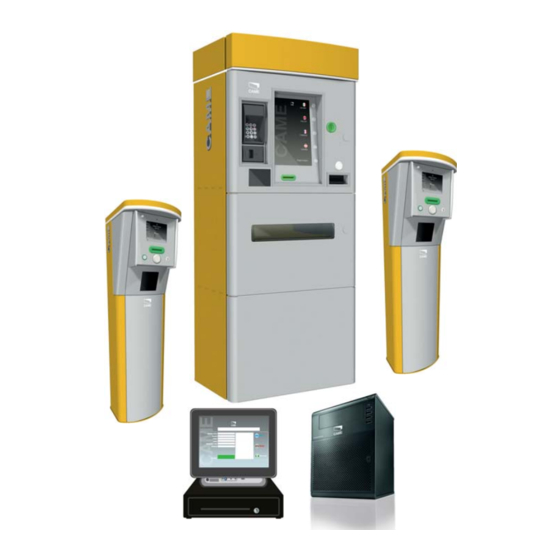
Parking system scheme and technical notes Available parking space sign camera Exit unit Manned cash register Entry unit Magnetic coil Barrier Automatic camera cash register The PS One is designed to work with "native” ETHERNET interface devices. This evolved management system, does away with any physical impediments linked to the system's development and lets you configure an unlimited number of peripherals: automatic cash-registers, entry and exit units, registered patrons accessways, pedestrian readers, and manned cash-registers. -
Page 4: Description Of Units Making Up The Ps One System
Description of units making up the PS One system Central server - The unit manages the software and all entry and exit devices and logs all events. The server can also monitor and handle (even remotely) the entry and exit passages. It also features all of the voip control unit functions needed to manage an integrated intercom system. -
Page 5: Technical Data
Technical data 001PSAC110 server Power supply 230 V Container Micro tower Microprocessor Dual Core 1.5 GHz AMD Turion II PC3-10600E DDR 3.8 GB (2 x 4 GB) 8 TB (4 x 2 TB 3.5” SATA drives) Network control Embedded NC107i PCI Express Gigabit Ethernet Server Adaptor Dimensions 267 x 260 x 210 mm Weight... - Page 6 001PSI121 entry unit - 001PSO131 exit unit Power supply 230 V AC 50/60 Hz Consumption when working 500 VA Consumption when idle 390 VA Peak draw 620 VA Protection rating IP 40 Weight 30 Kg Operating temperature -25° / + 55°C Depositing temperature 0°...
- Page 7 001PSM104 Roboticket tabletop reader/printer unit Power supply 240 Vca Risc 32 bit Fujitsu CPU board with up to 512 KB Flash Memory and type 8k x 8 bytes serial Eeprom N. 1 asynchronous RS232 optoisolated serial port for communicating with up to 115200 bps host.
-
Page 8: Connections Diagram
Connection diagram Receipt printer POS reader Intercom station Central server Manned manual cash register GSM ROUTER Roboticket Automatic Barcode cash register ETHERNET ticket reader Input-Output interface Entry unit Exit unit “EYE SYSTEM” OCR camera cameras Available parking space sign MAGNETIC MAGNETIC COILS COILS... -
Page 9: Overall Dimensions And Anchoring Bases
Overall dimensions and anchoring bases Entry unit (mm) Anchoring base Exit unit (mm) Anchoring base... - Page 10 Automatic cash register (mm)
-
Page 11: Sample Installation Scheme
Sample installation scheme The image shown below shows a sample, system installation layout with side-by-side entry/exit lanes; also shown are the measurements among the system components. These must be respected for the system to work properly. “OCR” license plates camera (mm) Entry detection coil “Eye System”... - Page 12 The entry and exit units are rated, taking into account an underlying base of at least 120 mm in height and 600 mm in width. Base Even the automatic cash-register has been sized taking into account an underlying base that is at least 120 mm high. Automatic cash-register user side Base...
-
Page 13: Entry Unit / Exit Unit Board - Description
Entry unit / exit unit board - description Traffic light fuse 12. LED signal lights Traffic light connection terminal 13. Input terminal Fans and heater connection terminals 14. Printer power supply terminal Barrier connection terminals 15. Vcc power supply input Barrier opening command relay switch 16. -
Page 14: Automatic Cash-Register Board - Description
Cash-register board - description 12. Input terminals VAC power supply inputs 13. Vcc power supply input Inter lighting connection terminal 14. Ground connection Fans and heater connection terminals 15. Fans and heater fuse Remote alarm output terminal 16. Internal lighting fuse Terminal Restart relay switch Network up sensor terminal Siren sensor alarm connection terminal... -
Page 15: Automatic Cash Register - Installation
Automatic cash register - installation 9.1 Setting up the cash-register base The following illustrations are mere examples, in that the space required for anchoring the automatic cash-register and accessories varies depending on the overall dimensions. It is the installer's responsibility to choose the most suited solution. - Dig a pit to house the anchoring plate (see drawing and measurements at “Overall dimensions and anchoring bases”) measuring at least 800 x 500 x 500 mm and lay any... - Page 16 9.2 Mounting the automatic cash register Closing element automatic cash-register supplied in three disassembled parts: • the base • the central element • the closing element Central element Base - Hitch three steel cables with hooks, on the end that can hoist at least 250 kg, to the eyelets on the head of the central element.
- Page 17 - Place the upper element atop the central one and fasten it by tightening the nine issued bolts. - Plug the LED connector into the upper element on the left side of the cash register. 9.3 ETHERNET power supply and connection - Inside the upper compartment, on the left side, connect the power supply cable coming from the base into its corresponding terminal.
- Page 18 - Make the ground connection. - Inside the upper compartment, on the left-hand side, connect the Ethernet cable to its socket. 9.4 Installing a back up generator (optional) The upper right-hand compartment of the cash-register, is set up for a back up generator in case of power outages. - Unplug the upper cable of the relative connection.
- Page 19 - Place the backup generator on the lower shelf. - Plug the end of the disconnected cable to the back of the back up generator. - Plug an additional cable into the back of the back up generator. - Plug the end of the additional cable in to the proper socket on the power supply bracket.
-
Page 20: Entry Unit / Exit Unit - Installation
Entry unit - exit unit - installing 10.1 Setting up the entry unit and exit unit bases The following illustrations are mere examples, in that the space required for anchoring the entry/exit unit and accesso- ries varies depending on the overall dimensions. It is the installer's responsibility to choose the most suited solution. - Dig a pit to house the anchoring plate (see drawing and measurements at “Overall dimensions and anchoring bases”) measuring at least 350 x 300 x 250 mm and lay any required... -
Page 21: Entry Unit / Exit Unit - Electrical Connections
Entry unit - exit unit - electrical connections 11.1 Connecting coils - On the left side of the post, find the bi-channel sensor, then connect up the coils (metal mass detector sensors). L3 L4 L5 L6 11.2 Connecting barriers - Remove the container cover to access the electrical board on the post. - Page 22 - On the board, find the connection to barriers terminal (see entry - exit unit board), then make the connections. 2A 3 2B 4 5 10 11.3 Traffic light connections - Find the board on the available parking space display connection terminal (see entry - exit unit board) and make the connections.
- Page 23 - Position and fasten the cover. 11.4 Power supply - Find the power supply terminal and make the connection. - Make the mass connections.
- Page 24 11.5 ETHERNET connection - At the lower end of the post, connect the Ethernet cable to its socket. 11.6 Switching on - Once all electrical connections are made, to start the entry and exit units press the switch on the left side of the unit. 11.7 Status signal LED Status signal LED There is an LED light atop the entry and exit units to show colour-...
-
Page 25: Manned Cash Register - Installation
11.8 LED input index on entry - exit unit board LED LIST STATUS OF COMPONENT INPUT 1 Coil 1 status INPUT 2 Coil 2 status INPUT 3 Use depends on how system is used INPUT 4 Use depends on how system is used INPUT 5 Use depends on how system is used INPUT 6... - Page 26 - Make the connections as shown in the figure. ETHERNET Printer/Roboticket POS connector connector connector Manual barcode Drawer Power supply reader connection connector - Restore the cover by tightening the four screws. 12.1 Roboticket Connections - Make the connections on the back of the roboticket reader/printer, as shown in the figure. Manual, manned cash register connection.
- Page 27 THIS PAGE LEFT INTENTIONALLY BLANK...
- Page 28 (+34) 91 52 85 009 127273, Moscow Moscow (+34) 91 46 85 442 (+7) 495 739 00 69 (+7) 495 739 00 69 (ext. 226) CAME United Kingdom Ltd. CAME United Kingdom Ltd. GREAT BRITAIN PORTUGAL CAME Portugal CAME Portugal...
Need help?
Do you have a question about the PS ONE SERIES and is the answer not in the manual?
Questions and answers