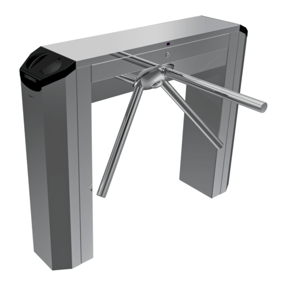
CAME TWISTER Installation Manual
Tripod turnstiles
Hide thumbs
Also See for TWISTER:
- Installation manual (13 pages) ,
- Instruction manual (25 pages) ,
- Installation manual (49 pages)

Related Manuals for CAME TWISTER


Summary of Contents for CAME TWISTER
- Page 1 TORNELLI A TRIPODE FA 0 0 613 - I T FA 006 13 M 0 4 MANUALE DI INSTALLAZIONE TWISTER Italiano English PST001 - PST002 - PST003 - PST004 Français Italiano Русский...
-
Page 2: Leggere Attentamente
ATTENZIONE! importanti istruzioni per la sicurezza delle persone: LEGGERE ATTENTAMENTE! LA NECESSARIA CONOSCENZA PURCHÉ SOTTO SORVEGLIANZA OPPURE DOPO CHE LE REMESSA ’ ’ • I ’ STESSE ABBIANO RICEVUTO ISTRUZIONI RELATIVE ALL USO SICURO DELL APPARECCHIO L PRODOTTO DEVE ESSERE DESTINATO SOLO ALL USO PER IL QUALE È... -
Page 3: Dati Tecnici
Questo simbolo indica parti riguardanti la sicurezza. ☞ Questo simbolo indica cosa comunicare all’utente. SALVO DOVE ESPRESSAMENTE INDICATO, LE OPERAZIONI SI INTENDONO VALIDE PER TUTTI I MODELLI DELLA SERIE TWISTER A PRESCINDERE DALLE IMMAGINI MOSTRATE. DESCRIZIONE 001PST001 Tornello elettromeccanico bidirezionale in acciaio AISI 304 satinato completo di scheda elettronica, sensori transponder, frecce di direzione a LED con display, semafori laterali e deceleratore idraulico. - Page 4 Descrizione delle parti PST001 PST001 PST002 PST002 1. Gambe 9. Semafori laterali 1. Gambe 8. Semafori laterali 2. Tripode 10. Meccanismo 2. Tripode 9. Meccanismo 3. Cassone 11. Quadro comando TOR100 3. Cassone 10. Quadro comando TOR100 4. Carter 12. Serratura del coperchio 4.
-
Page 5: Impianto Tipo
Dimensioni (MM) 1200 Impianto tipo Tornello a tripode Frecce di direzione con display Scatola di derivazione Sensore transponder Transenna Semafori laterali Esempi di applicazione ⚠ L’uscita gestita da un tornello non deve essere considerata un’uscita di emergenza! Prevedere sempre anche un’uscita di emergenza e per disabili. Installazione standard Installazione a ridosso muro Installazione multipla... -
Page 6: Installazione
INDICAZIONI GENERALI PER L’INSTALLAZIONE ⚠ L’installazione deve essere effettuata da personale qualificato ed esperto e nel pieno rispetto delle normative vigenti. Verifiche preliminari ⚠ Prima di procedere all’installazione del tornello è necessario: • se necessari, prevedere i tubi corrugati per il passaggio dei cavi elettrici; •... - Page 7 Inserire il tripode sul perno e fissarlo con vite M8x20 e il coperchio Fissare i bracci alla testa del tripode con viti M10x60 e rondelle a testa piana. PST001 PST001 PST002 PST002 PST003 PST003 Fissaggio del tornello Il pavimento su cui si fissa il tornello deve essere La posizione su cui fissare il tornello dipende dalle Forare sui punti contrassegnati e infilare i tasselli perfettamente livellato.
-
Page 8: Collegamenti Elettrici
COLLEGAMENTI ELETTRICI ⚠ Prima di intervenire sulla scheda elettronica, togliere la tensione di linea. TABELLA FUSIBILI TOR100A TOR100B Alimentazione scheda elettronica (V - 50/60 Hz): 120 - 230 AC. 1,6 (230 V) Alimentazione dispositivi di comando: 24 V AC. Fusibili di linea (A) 3,15 (120 V) ⚠... - Page 9 Dispositivi già collegati (tutti i modelli) Sensore di passaggio Bianco Marrone Verde Trasformatore Bianco Rosso (230 V AC) Bianco Nero (120 V AC) Elettroblocco Rosso Rosso Rosso Rosso PST003 PST003 PST003 PST003 PST003 PST003 Fotocellule Sensori anti-scavalcamento Buzzer Fotocellula Sensore Fotocellula Sensore Dispositivi da collegare...
-
Page 10: Dispositivi Di Comando
Schede di decodifica Le schede di decodifica R700 servono per comandare il tornello con i sensori di prossimità (TSP00) e la Memory Roll per salvare e caricare tutte le imposta- zioni compresi gli utenti registrati in un’altra scheda. ⚠ Per un corretto funzionamento, prima di inserire una qualsiasi scheda a innesto (es.: AF, R700), è OBBLIGATORIO TOGLIERE LA TENSIONE DI LINEA e , se presenti, scollegare le batterie. - Page 11 PST004 PST004 Funzione caduta braccio In caso di blackout, il braccio Al ripristino dell’alimentazione, orizzontale scende e libera il sollevare il braccio per riarmarlo. passaggio. Fissaggio dei carter laterali ⚠ Verificare che il deceleratore idraulico sia regolato correttamente (vedi capitolo dedicato). Montare i carter laterali e fissarli con le viti.
-
Page 12: Struttura Menu
Struttura menu ☞ Le funzioni da F-1 a F-4 e da F-14 a F-17 sono dedicate alla gestione degli accessi con sensori transponder (di serie ) e appaiono solo se è collegato il PST001 PST001 lettore TSP00. ☞ Le funzioni F-2, F-3 e F-4 compaiono sul display solo se viene creata la tessera MASTER. F - 1 <... - Page 13 Programmazione con transponder (tessera MASTER) Per poter programmare le funzioni con transponder è necessario creare la tessera MASTER (F-1) con la pulsantiera. Creazione tessera master ☞ Se il punto nel display lampeggia significa che non è stata ancora creata la tessera Master. Premere ENTER per 2 volte. Il LED del transponder “SENSORE 1”...
-
Page 14: Menu Funzioni
Menu funzioni Creazione tessera MASTER per la programmazione delle funzioni con tessera transponder. Creazione nuova tessera (fi no a max. 500 tessere). Cancellazione tessera. Selezionare il numero assegnato alla tessera da cancellare con il pulsante o posizionare la tessera sul transponder (SENSORE 1), sul display verrà... -
Page 15: Manutenzione
OPERAZIONI FINALI ⚠ Verificare che il deceleratore idraulico sia regolato correttamente (vedi capitolo dedicato). ⚠ Posizionare il cavo del display in modo che non si impigli nelle parti interne in movimento. Mettere il coperchio e chiudere la serratura con la chiave. ⚠... -
Page 16: Riferimenti Normativi
DISMISSIONE E SMALTIMENTO ☞ CAME CANCELLI AUTOMATICI S.p.A. implementa all’interno dei propri stabilimenti un Sistema di Gestione Ambientale certificato e conforme alla norma UNI EN ISO 14001 a garanzia del rispetto e della tutela dell’ambiente. - Page 17 TRIPOD TURNSTILES FA 00613 - EN INSTALLATION MANUAL TWISTER PST001 - PST002 - PST003 - PST004 English...
-
Page 18: Read Carefully
WARNING! important safety instructions for people: READ CAREFULLY! PARTS ALL ANCHORING POINTS INCLUDING CABLES AND ANY ACCESSIBLE CONNEC REMISE • T TIONS EEP ANY HINGES MOVING JOINTS AND FRICTION POINTS PROPERLY LUBRI HIS PRODUCT SHOULD ONLY BE USED FOR THE PURPOSE FOR WHICH IT WAS •... -
Page 19: Intended Use
This symbol indicates parts about safety. ☞ This symbol tells you what to say to the end users. UNLESS EXPRESSELY STATED THE OPERATIONS SHALL BE VALID FOR ALL MODELS OF THE TWISTER SERIES REGARDLESS OF THE DRAWINGS SHOWN IN THIS MANUAL. DESCRIPTION 001PST001 Bidirectional electromechanical turnstile in satin fi... - Page 20 Description of the components PST001 PST001 PST002 PST002 1. Legs 10. Mechanism 1. Legs 9. Mechanism 2. Tripod 11. TOR100 control panel 2. Tripod 10. TOR100 control panel 3. Housing 12. Cover lock 3. Housing 11. Cover lock 4. Casing 13.
-
Page 21: Example Of A System
Dimensions (MM) 1200 Example of a system Tripod turnstile Direction arrows with display Junction box Transponder sensor Barrier Lateral traffic lights Examples of use ⚠ A turnstile regulated exit should not be considered an emergency exit! Always provide an exit for emergency situations and for the physically impaired. Standard installation Wall flanking installation Multiple installation... -
Page 22: General Instructions For Installation
GENERAL INSTRUCTIONS FOR INSTALLATION ⚠ Installation must be carried out by qualified and experienced personnel in compliance with applicable regulations. Preliminary checks ⚠ The following is necessary before installing the turnstile: • if necessary provide for the corrugated tubing to route electrical cables; •... - Page 23 Fit the tripod into the pin and fix with screws M8x20 and cover Attach the arms to the head of the tripod with screws M10x60 and flat head washers. PST001 PST001 PST002 PST002 PST003 PST003 Securing the turnstile The floor on which is fixed the turnstile must be The turnstile anchoring spot depends on the size Drill the marked holes and insert the dowels into perfectly level.
-
Page 24: Electrical Connections
ELECTRICAL CONNECTIONS ⚠ Remove line voltage before intervening on the control board. FUSE TABLE TOR100A TOR100B Control board power supply (V - 50/60 Hz): 120 - 230 AC. 1.6 (230 V) Control device power supply: 24 V AC. Line fuses (A) 3.15 (120 V) ⚠... - Page 25 Devices already connected (all models) Entrance/exit sensor White Brown Green Transformer White Red (230 V AC) White Black (120 V AC) Blue Blue Electric lock Photocells Protection against climbing over sensors Buzzer PST003 PST003 PST003 PST003 PST003 PST003 Photocell Sensor Photocell Sensor Devices to be connected...
-
Page 26: Control Devices
Decoder card The R700 decoder cards control the turnstile with the proximity sensors (TSP00) and the Memory Roll to save and load all the settings including users stored in another card. ⚠ For proper operation, before inserting any plug-in card (e.g.: AF, R700), the LINE VOLTAGE MUST BE REMOVED and any batteries disconnected. Control devices Terminal block for 24 V AC powering of accessories with maxi- mum current and power draw of 250 mA and 35 W respectively. - Page 27 Arm drop function PST004 PST004 In the event of a power failure, the Lift the arm and reset it after horizontal arm drops to free the power has been restored. passage. Securing the side casings ⚠ Make sure that the hydraulic damper is correctly adjusted (see specific chapter). Fit the side casings and secure with the screws.
-
Page 28: Menu Structure
Menu structure ☞ The functions from F-1 to F-4 and from F-14 to F-17 are reserved for access control via transponders ( series) and are displayed only if the TSP00 reader PST001 PST001 is connected. ☞ The functions F-2, F-3 and F-4 appear on the display only if the MASTER card is created. F - 1 <... - Page 29 Programming via transponder (MASTER card) The MASTER card (F-1) must be created using the keyboard in order to program the functions using the transponder. Creating a Master card ☞ A flashing display dot means that the Master card has not been created yet. Press ENTER 2 times. The LED of the transponder “SENSOR 1”...
-
Page 30: Function Menu
Function menu Create a MASTER card for function programming with a transponder card. Create a new card (up to 500 cards). Delete a card. Select the number assigned to the card to delete using the key or place the card on the transponder (SENSOR 1); the display will show the card number. -
Page 31: Final Operations
FINAL OPERATIONS ⚠ Make sure that the hydraulic damper is correctly adjusted (see specific chapter). ⚠ Place the display cable out of the way of internal moving parts to avoid it from getting caught. Place the cover back on and engage the lock with the key. ⚠... -
Page 32: Dismantling And Disposal
☞ CAME CANCELLI AUTOMATICI S.p.A. implements an EN ISO 14001-certified and compliant Environmental Management System at its plants, to ensure environmental protection. Please continue our efforts to protect the environment, something that CAME considers to be one of the foundations in developing its business and market strategies, simply by observing brief recommendations as regards disposal: DISPOSAL OF PACKAGING Packaging components (cardboard, plastic, etc.) can be disposed of together with normal household waste without any difficulty, by simply separating the different types of... -
Page 33: Manuel D'installation
TOURNIQUETS À TROIS BRANCHES FA00613-FR MANUEL D'INSTALLATION TWISTER PST001 - PST002 - PST003 - PST004 Français... - Page 34 ATTENTION ! Instructions importantes pour la sécurité des personnes : À LIRE ATTENTIVEMENT ! MANŒUVRE DU TOURNIQUET ONSERVER HORS DE LEUR PORTÉE LES DISPOSITIFS DE VANT PROPOS • C COMMANDE À DISTANCE ÉMETTEURS OU TOUT AUTRE DISPOSITIF DE COMMANDE E PRODUIT NE DEVRA ÊTRE DESTINÉ QU À...
-
Page 35: Utilisation Prévue
Ce symbole indique des parties concernant la sécurité. ☞ Ce symbole indique ce qui doit être communiqué à l'utilisateur. SAUF INDICATION CONTRAIRE, LES OPÉRATIONS SONT VALABLES POUR TOUS LES MODÈLES DE LA SÉRIE TWISTER INDÉPENDAMMENT DES IMAGES PROPOSÉES. DESCRIPTION 001PST001 Tourniquet électromécanique bidirectionnel en acier AISI 304 satiné, avec carte électronique, capteurs badges, fl... -
Page 36: Description Des Parties
Description des parties PST001 PST001 PST002 PST002 1. Pieds 9. Feux de signalisation latéraux 1. Pieds 8. Feux de signalisation latéraux 2. Tripode 10. Mécanisme 2. Tripode 9. Mécanisme 3. Caisson 11. Armoire de commande TOR100 3. Caisson 10. Armoire de commande TOR100 4. -
Page 37: Installation Standard
Dimensions (MM) 1200 Installation standard Tourniquet à trois branches Flèches directionnelles avec afficheur Boîtier de dérivation Capteur transpondeur Barrière Feux de signalisation latéraux Exemples d'application ⚠ La sortie gérée par un tourniquet ne saurait être considérée comme une sortie de secours ! Il faut donc toujours prévoir une sortie aussi bien de secours que pour les personnes handicapées. -
Page 38: Contrôles Préliminaires
INDICATIONS GÉNÉRALES POUR L'INSTALLATION ⚠ L’installation doit être effectuée par du personnel qualifié et dans le plein respect des normes en vigueur. Contrôles préliminaires ⚠ Avant d'installer le tourniquet, il faut : • si nécessaire, prévoir les tuyaux ondulés pour le passage des câbles électriques ; •... - Page 39 Appliquer le tripode sur l'axe et le fixer à l'aide d'une vis M8x20 et du couvercle Fixer les bras à la tête du tripode à l'aide de vis M10x60 et de rondelles à tête plate. PST001 PST001 PST002 PST002 PST003 PST003 Fixation du tourniquet Le sol sur lequel sera fixé...
-
Page 40: Branchements Électriques
BRANCHEMENTS ÉLECTRIQUES ⚠ Avant d'intervenir sur la carte électronique, la mettre hors tension. TABLEAU FUSIBLES TOR100A TOR100B Alimentation carte électronique (V - 50/60 Hz) : 120 - 230 AC. 1,6 (230 V) Alimentation des dispositifs de commande : 24 V AC. Fusibles de ligne (A) 3,15 (120 V) ⚠... - Page 41 Dispositifs déjà connectés (tous les modèles) Capteur de passage Blanc Marron Vert Transformateur Blanc Rouge (230 V AC) Blanc Noir (120 V AC) Bleu Bleu Dispositif de verrouillage électrique Rouge Rouge Rouge Rouge PST003 PST003 PST003 PST003 PST003 PST003 Photocellules Capteurs antifraude Buzzer Photocellule...
-
Page 42: Dispositifs De Commande
Cartes de décodage Les cartes de décodage R700 permettent de commander le tourniquet avec les capteurs de proximité (TSP00) tandis que la Memory Roll permet de sauve- garder et de télécharger toutes les configurations, y compris les utilisateurs enregistrés dans une autre carte. ⚠... - Page 43 PST004 PST004 Fonction chute du bras En cas de coupure de courant, Au rétablissement du courant, le bras horizontal descend pour soulever le bras pour le réarmer. dégager le passage. Fixation des carters latéraux ⚠ S'assurer du réglage correct du décélérateur hydraulique (voir chapitre dédié). Monter les carters latéraux et les fixer à...
-
Page 44: Structure Menu
Structure menu ☞ Les fonctions de F-1 à F-4 et de F-14 à F-17 sont dédiées à la gestion des accès par capteurs de badges (de série ) et n'apparaissent qu'en cas de PST001 PST001 connexion du lecteur TSP00. ☞ Les fonctions F-2, F-3 et F-4 n'apparaissent à l'écran que si la carte MAÎTRE a été créée. F - 1 <... - Page 45 Programmation par transpondeur (carte MAÎTRE) Pour pouvoir programmer les fonctions par transpondeur, il est nécessaire de créer une carte MAÎTRE (F-1) au moyen du clavier. Création carte maître ☞ Le clignotement du point à l'écran signale que la carte Maître n'a toujours pas été créée. Appuyer 2 fois sur ENTER. Le VOYANT du transpondeur «...
-
Page 46: Menu Fonctions
Menu fonctions Création carte MAÎTRE pour la programmation des fonctions avec carte transpondeur. Création nouvelle carte (jusqu'à 500 cartes max.). Suppression carte. Sélectionner le numéro attribué à la carte à supprimer avec le bouton ou bien positionner la carte sur le transpondeur (CAPTEUR 1). L'écran affi chera le numéro de la carte. -
Page 47: Entretien
OPÉRATIONS FINALES ⚠ S'assurer du réglage correct du décélérateur hydraulique (voir chapitre dédié). ⚠ Positionner le câble de l'afficheur de manière à ce qu'il ne reste pas coincé dans les parties internes en mouvement. Mettre le couvercle et fermer à clé. ⚠... - Page 48 MISE AU REBUT ET ÉLIMINATION ☞ CAME CANCELLI AUTOMATICI S.p.A. adopte dans ses établissements un Système de Gestion Environnementale certifié et conforme à la norme UNI EN ISO 14001 qui garantit le respect et la sauvegarde de l'environnement.
- Page 49 ТУРНИКЕТЫ- ТРИПОДЫ FA00613-RU ИНСТРУКЦИЯ ПО МОНТАЖУ TWISTER PST001 - PST002 - PST003 - PST004 Русский...
- Page 50 • Э НЫМИ КОМАНДНЫМИ УСТРОЙСТВАМИ ИЛИ НАХОДИТЬСЯ В ЗОНЕ ДВИЖЕНИЯ ТУР ТО ИЗДЕЛИЕ ДОЛЖНО ИСПОЛЬЗОВАТЬСЯ ИСКЛЮЧИТЕЛЬНО ПО НАЗНАЧЕНИЮ . Н Л . CAME S. НИКЕТА ЕОБХОДИМО ДЕРЖАТЬ БРЕЛОКИ ПЕРЕДАТЧИКИ И ДРУГИЕ УСТРОЙСТВА ЮБОЕ ДРУГОЕ ПРИМЕНЕНИЕ РАССМАТРИВАЕТСЯ КАК ОПАСНОЕ УПРАВЛЕНИЯ В НЕДОСТУПНОМ ДЛЯ ДЕТЕЙ МЕСТЕ ВО ИЗБЕЖАНИЕ СЛУЧАЙНОГО...
-
Page 51: Условные Обозначения
⚠ Этот символ обозначает раздел, связанный с вопросами безопасности. ☞ Этот символ обозначает раздел, предназначенный для ознакомления конечного пользователя. ЗА ИСКЛЮЧЕНИЕМ СПЕЦИАЛЬНО ОГОВОРЕННЫХ СЛУЧАЕВ ОПИСАННЫЕ ИНСТРУКЦИИ ПРИМЕНИМЫ КО ВСЕМ МОДЕЛЯМ ТУРНИКЕТОВ СЕРИИ TWISTER НЕЗАВИСИМО ОТ ПРИЛАГАЕМЫХ ИЛЛЮСТРАЦИЙ. ОПИСАНИЕ 001PST001 Двусторонний электромеханический турникет из сатинированной нержавеющей стали AISI 304, укомплектованный электронной... -
Page 52: Основные Компоненты
Основные компоненты PST001 PST001 PST002 PST002 1. Стойки 10. Доводчик 1. Стойки 9. Доводчик 2. Трипод 11. Блок управления TOR100 2. Трипод 10. Блок управления TOR100 3. Корпус 12. Замок крышки 3. Корпус 11. Замок крышки 4. Кожух 13. Винты с шайбами для 4. -
Page 53: Габаритные Размеры
Габаритные размеры (MM) 1200 Вариант типовой установки Турникет-трипод Указатель направления движения Разветвительная коробка Проксимити-считыватель Переносное ограждение Боковые светофоры Варианты установки ⚠ Запрещена установка турникетов на аварийных запасных выходах! Необходимо обязательно предусмотреть наличие аварийных выходов и вы- ходов для людей с ограниченными физическими способностями. Типовая... - Page 54 ОБЩИЕ ИНСТРУКЦИИ ПО МОНТАЖУ ⚠ Монтаж должен производиться квалифицированным персоналом в полном соответствии с требованиями действующих норм безопасности. Предварительные проверки ⚠ Перед началом монтажных работ выполните следующее: • при необходимости подготовьте гофрошланги для электропроводки; • убедитесь в том, что питание блока управления осуществляется от отдельной линии с соответствующим автоматическим выключателем, с рас- стоянием...
- Page 55 Установите трипод на наклонную ось и зафиксируйте конструкцию с Прикрепите штанги к верхней части трипода, используя винты M10 x 60 помощью винта M8x20 и заглушки с плоскими шайбами. PST001 PST001 PST002 PST002 PST003 PST003 Монтаж турникета Поверхность, предназначенная для установки Выберите...
-
Page 56: Электрические Подключения
ЭЛЕКТРИЧЕСКИЕ ПОДКЛЮЧЕНИЯ ⚠ Перед проведением каких-либо настроек, регулировок или подключений в блоке ТАБЛИЦА ПРЕДОХРАНИТЕЛЕЙ TOR100A TOR100B управления необходимо отключить сетевое электропитание. 1,6 (230 В) Напряжение электропитания блока управления ~120 - 230 В (50/60 Гц). Входные предохранители (А) 3,15 (120 В) Напряжение... - Page 57 Подключенные устройства (все модели) Датчик контроля движения Белый Коричневый Зеленый Трансформатор Белый Красный (~230 В) Белый Черный (~120 В) Синий Синий Электрозамок Красный Красный Красный Красный PST003 PST003 PST003 PST003 PST003 PST003 Фотоэлементы Датчики давления Зуммер Фотоэлемент Датчик Фотоэлемент Датчик Подключаемые...
- Page 58 Дополнительные платы Платы декодеров R700 необходимы для управления турникетом с помощью проксимити-считывателей (TSP00), а карта памяти — для сохране- ния всех настроек, включая зарегистрированных пользователей, и загрузки их на другую плату. ⚠ Для обеспечения исправной работы перед тем как вставить плату (например: AF, R700), ОТКЛЮЧИТЕ ЭЛЕКТРОПИТАНИЕ и отсоедините аккумуля- торы...
- Page 59 PST004 PST004 Функция опускания штанги В случае кратковременного После возобновления отключение электроэнергии электроснабжения поднимите горизонтальная штанга штангу, чтобы снова привести опускается вниз, освобождая ее в рабочее состояние. проход. Крепление боковых кожухов ⚠ Проверьте регулировку гидравлического доводчика (см. соответствующую главу). Установите кожухи и зафиксируйте их с помощью винтов. ПРОГРАММИРОВАНИЕ...
-
Page 60: Структура Меню
Структура меню ☞ Функции с F-1 по F-4 и с F-14 по F-17 предназначены для управления доступом с помощью считывателей проксимити-карт ( в серийной PST001 PST001 комплектации) и отображаются только при наличии считывателя TSP00. ☞ Функции F-2, F-3 и F-4 отображаются на дисплее, только если была создана МАСТЕР-карта. F - 1 <... - Page 61 Программирование с помощью проксимити-считывателй (МАСТЕР-карты) Для программирования функций с помощью проксимити-считывателй необходимо создать МАСТЕР-карту (F-1), воспользовавшись кнопочной панелью. Создание МАСТЕР-карты ☞ Мигающая на дисплее точка указывает на то, что МАСТЕР-карта еще не создана. Дважды нажмите клавишу ENTER. Светодиодный индикатор считывателя СЧИТЫВАТЕЛЬ 1 мигает КРАСНЫМ светом, а на дисплее появляются линии. СЧИТЫВАТЕЛЬ...
- Page 62 Меню "Функции" Создание МАСТЕР-карты для входа в меню и программирования функций. Создание новой карты (до 500 карт). Удаление карты. Выберите число, соответствующее номеру удаляемой карты, с помощью кнопки или приложив карту к считывателю (СЧИТЫВАТЕЛЬ 1). На дис- плее появится номер карты. Подтвердите удаление, нажав на клавишу ENTER. Удаление...
-
Page 63: Заключительные Работы
ЗАКЛЮЧИТЕЛЬНЫЕ РАБОТЫ ⚠ Проверьте регулировку гидравлического доводчика (см. соответствующую главу). ⚠ Расположите кабель дисплея так, чтобы он не соприкасался с внутренними движущимися частями. Установите крышку и закройте ее на ключ. ⚠ РЕГУЛИРОВКА ГИДРАВЛИЧЕСКОГО ДОВОДЧИКА Правильная регулировка гидравлического доводчика является обязательной предпосылкой исправной работы турникета и уменьшения механической... - Page 64 поминаемая карта уже сохранена в памяти устройства. УТИЛИЗАЦИЯ ☞ CAME CANCELLI AUTOMATICI S.p.A. имеет сертификат системы защиты окружающей среды UNI EN ISO 14001, гарантирующий экологическую безопасность на ее заводах. Мы просим, чтобы вы продолжали защищать окружающую среду. САМЕ считает одним из фундаментальных пунктов стратегии рыночных...
Need help?
Do you have a question about the TWISTER and is the answer not in the manual?
Questions and answers